

Abstract
Inositol-1,4,5-trisphosphate receptors (InsP3Rs) are ubiquitous ion channels responsible for cytosolic Ca2+ signalling and essential for a broad array of cellular processes ranging from contraction to secretion, and from proliferation to cell death. Despite decades of research on InsP3Rs, a mechanistic understanding of their structure–function relationship is lacking. Here we present the first, to our knowledge, near-atomic (4.7 Å) resolution electron cryomicroscopy structure of the tetrameric mammalian type 1 InsP3R channel in its apo-state. At this resolution, we are able to trace unambiguously ~85% of the protein backbone, allowing us to identify the structural elements involved in gating and modulation of this 1.3-megadalton channel. Although the central Ca2+-conduction pathway is similar to other ion channels, including the closely related ryanodine receptor, the cytosolic carboxy termini are uniquely arranged in a left-handed α-helical bundle, directly interacting with the amino-terminal domains of adjacent subunits. This configuration suggests a molecular mechanism for allosteric regulation of channel gating by intracellular signals.
InsP3Rs belong to a superfamily of tetrameric cation channels that includes functionally distinct groups of ion channels (for example, K+, Na2+, Ca2+, transient receptor potential and cyclic nucleotide-gated channels). A common architectural feature of these channels is their central ion-permeation pore consisting of four membrane-spanning subunits or domains. However, these channels are quite different with respect to their activation and ability to respond to extracellular and intracellular stimuli, defining their particular roles in a wide range of cellular processes. Localized within the membranes of intracellular Ca2+ stores such as the endoplasmic/sarcoplasmic reticulum, InsP3R channels have crucial roles in a variety of physiological functions, including gene transcription, fertilization, hormone secretion, metabolic regulation, immune responses, apoptosis, learning and memory. Their malfunction is associated with abnormal intracellular Ca2+ levels linked to pathological conditions in humans, such as cardiac hypertrophy, heart failure, Alzheimer, Parkinson and Huntington diseases, cancer and stroke.
Type 1 InsP3R (InsP3R1) exemplifies the family of InsP3-gated Ca2+ release channels, which is comprised of three homologous isoforms (types 1–3). InsP R1 is the predominant Ca2+ release channel in cerebellar Purkinje cells and best characterized member of the family. Despite its profound importance in physiology, a mechanistic basis for InsP3R1 function has remained elusive, largely owing to the lack of a detailed architecture of the intact InsP3R channel.
The quaternary structure of the entire InsP3R1 assembly was controversial1 until our previous intermediate resolution electron cryomicroscopy (cryo-EM) structure2,3. While this structure is critical in providing the foundation for further structure–function studies, the resolution was insufficient to reveal the mechanistic features underlying the channel function. Furthermore, X-ray crystal structures for portions of InsP3R1 are available but limited to small soluble pieces (~15% of the 314-kilodalton protein)4–7. Knowledge of the full-length InsP3R architecture with atomistic details is paramount to understanding the molecular mechanism underlying channel function in both healthy and disease states. Here we present a cryo-EM structure and model of the entire InsP3R1 channel in its ligand-free state determined at an overall 4.7 Å resolution by single-particle cryo-EM. The structure reveals distinct features that allow us to infer its gating mechanism.
Overall architecture of InsP3R1
In this work, InsP3R1 from rat cerebellum was detergent-purified without adding InsP3 or other channel-specific ligands, as previously described2. Before vitrification, InsP3R1 channel particles were stabilized by depletion of Ca2+, conditions that favour a closed state of the channel (Methods). The final map was reconstructed to 4.7 Å resolution (Extended Data Figs 1 and 2). The shape and overall dimensions of the tetrameric InsP3R1 3D density map are in excellent agreement with our previously published cryo-EM structure2: four subunits are arranged around a central channel axis forming two major regions, the bulky cytosolic region connected via ‘stalk’ densities to the transmembrane region (Extended Data Fig. 3 and Supplementary Video 1).
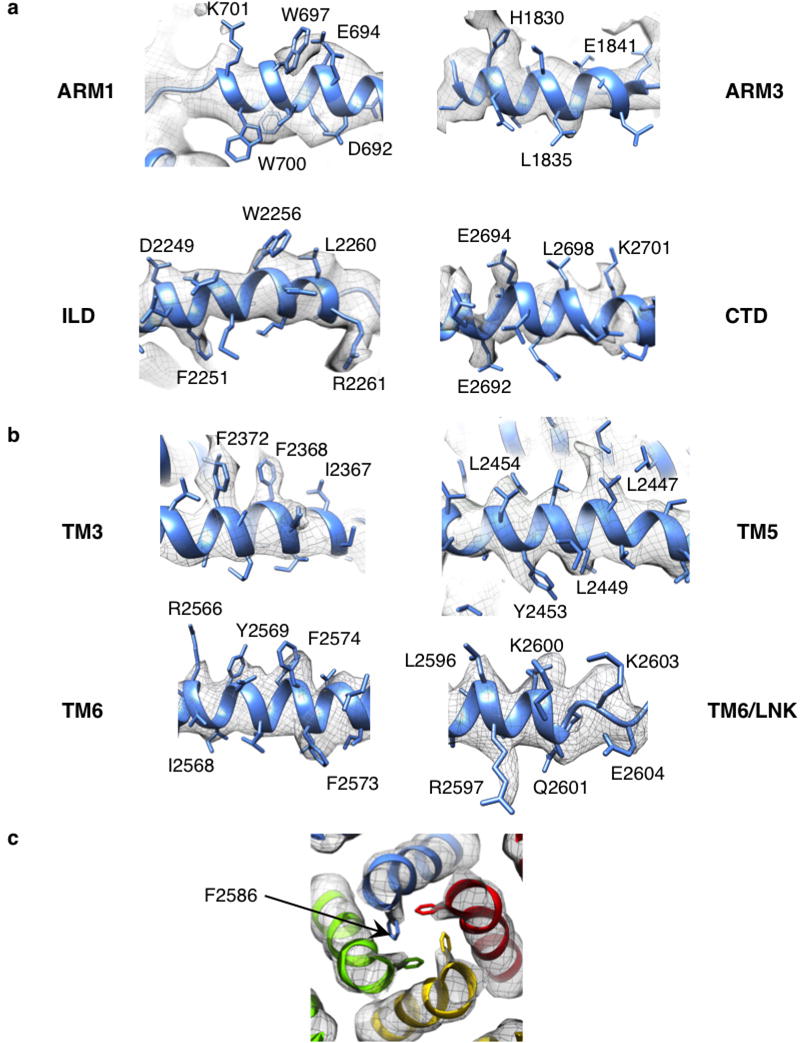
Resolution and resolvability of structural features are different in various parts of the map (Extended Data Fig. 2c) as suggested in our previous studies2,3. These differences are probably, at least in part, due to genuine flexibility associated with particular domains. Additionally, the potential presence of InsP3R1 splice variants may introduce some degree of compositional heterogeneity within the purified samples8–10. Thus, it is conceivable that these regions comprising alternatively spliced sequences represent some of the relatively poorly resolved regions of the map (Extended Data Figs 4a and 5). However, the transmembrane helices are well resolved in the map with many bulky side chains visible in the density map (Extended Data Fig. 6). Despite the observed variations in resolvability, we were able to model the backbone topology for 2,327 of 2,750 amino acids in the full-length InsP3R1 protein (Fig. 1).
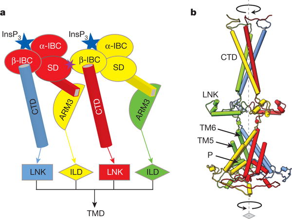
Figure 1. Overview of InsP3R1 structure.
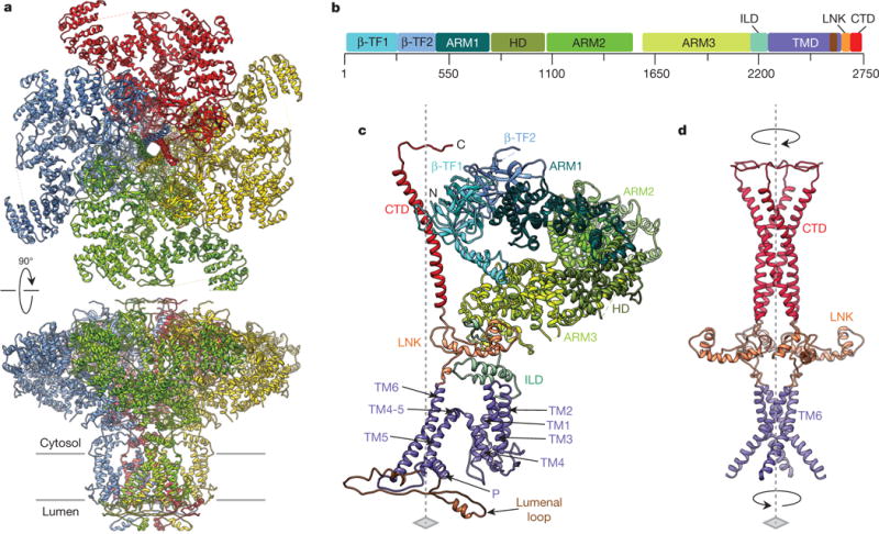
a, Structure of InsP3R1 visualized in two orthogonal orientations: view from cytosol and side view along the membrane plane. Subunits are colour-coded. b, Linear representation of InsP3R1 structural domains (GI accession 17380349): domains are annotated in the text, HD is the α-helical domain. c, An individual subunit colour-coded by domain. d, Central core structure of tetrameric InsP3R1. Four-fold axis is indicated by the dashed line; arrows indicate the bundle handedness.
Subunit folds and tetrameric assembly
The individual InsP3R1 subunit is made up of ten domains (Fig. 1b, c), arranged within the tetrameric channel assembly around a central four-fold axis to fulfill specific functions, including channel stability, ion transport, ligand binding and regulation. In our model, ~90% of the protein sequence extends beyond the membrane into the cytosol including most of the N-terminal protein sequence and the C-terminal tail (Extended Data Fig. 5). The remaining portion encompasses the transmembrane and lumenal domains.
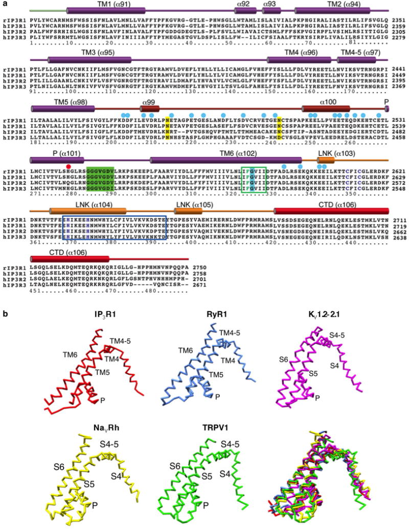
At the amino terminus of each subunit, two contiguous β-trefoil domains (β-TF1 and β-TF2; residues 1–436) form apical densities around the central four-fold axis of the cytosolic region (Fig. 1b, c, Extended Data Fig. 4c and Supplementary Video 2). After β-TF2, there is a clear α-helical pattern (residues 437–2192) forming three consecutive armadillo solenoid folds (ARM1–ARM3), with an α-helical domain between ARM1 and ARM2. After ARM3, the subunit extends into the ‘intervening lateral’ domain (ILD, residues 2193– 2272) that contains two anti-parallel β-strands followed by a helix–turn–helix motif. The C terminus of the ILD is connected to the transmembrane region, comprised of six α-helices (TM1–TM6), a pore (P)-helix and three lumenal loops. The C-terminal domain (CTD) contains an ~80 Å long α-helix (residues 2681–2731) connected at its N terminus to TM6 via a helical linker domain (LNK, residues 2601–2680) (Fig. 1b–d).
Unique to InsP3R1, the entire tetrameric architecture of the channel is built around two four-helix bundles: one transmembrane and one cytosolic bundle that together form a central core along the fourfold axis (Fig. 1d). The transmembrane bundle is right-handed and formed by the TM6 helices (one from each subunit), whereas the cytosolic bundle contains the CTD α-helix from each subunit packed in a left-handed fashion. The latter spans most of the cytosolic region and earlier was described as the ‘plug’ density2. The transmembrane and cytosolic helical bundles are connected via four LNK domains (one from each subunit), each consisting of two short, nearly orthogonal helices.
Ca2+ permeation pathway of InsP3R1
The cryo-EM densities comprising the transmembrane region of InsP3R1 are the most-resolved portions of the map (Extended Data Fig. 2c). As such, it was possible to construct a complete model for the transmembrane domains (TMDs), which constitute the ion-permeation pathway along the central four-fold axis (Fig. 2a, b). The Ca2+ conduction path is lined by four TM6 helices, tilted ~37°relative to the membrane normal and packed in a right-handed bundle (Figs 2a, b and 3), a conformation originally observed in the KcsA channel11. The TM6 helices are ~55 Å long, extending beyond the cytosolic membrane surface and curving radially to form a tapering path for ions (Fig. 3a). The TM5 helices are packed against the TM6 helices (Fig. 2 and Supplementary Video 2). The lumenal loop between the TM5 and TM6 helices contains a short P-helix (residues 2531–2544) and a selectivity filter comprising highly conserved residues 2546–2552 (Extended Data Figs 7a and 8c)2. The central bundle of TM5 and TM6 helices is linked to the flanking TM1–TM4 bundle via an amphipathic α-helix (TM4–5), which lies parallel to the cytosolic membrane leaflet (Fig. 2). Mutations in the TM4–5 helix have been shown to affect the channel gating suggesting that this helix may influence the motions of the pore-lining helices of InsP3R (ref. 12). As observed in the other known tetrameric cation channels, TM4 cradles TM5 of the adjacent subunit (Fig. 2a).
Figure 2. Structure of the transmembrane domains.
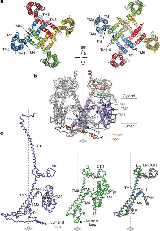
a, Arrangement of transmembrane helices in tetrameric InsP3R1; subunits are colour-coded and viewed from cytosol (left) and lumen (right). b, The structures of two opposing TMDs are superimposed on cryo-EM densities; view is along the membrane plane. One subunit is colour-coded by domain. c, Structural comparison of TMDs from InsP3R1 (left) and RyR1 (PDB accession 3J8H, middle); structurally conserved domains are shown overlapped (right); a root mean squared deviation (r.m.s.d.) value between the TMDs is 1.135 Å for 77 atom pairs.
Figure 3. Detailed structure of the Ca2+ conduction pathway.

a, A bundle of TM6 helices shape the ion permeation pathway. A series of hydrophobic residues within a constriction region of the channel pore are labelled. The wire cage is the void-density along the ion conduction pathway; colour-coded by hydrophobicity (right). b, The lumenal vestibule lined by P-helices and selectivity filter (SF) loops viewed along the four-fold axis from the lumen; insert shows the close-up view.
The structure of the pore is wider at the lumenal face of the membrane, where the P-helices and selectivity filter are located (Fig. 3). His2541 is present at the C-terminal end of the P-helix and forms a ring of positive charges on the lumenal side, possibly repelling Ca2+ in the non-conducting channel. In order for Ca2+ to pass beyond the lumenal vestibule, we propose that the P-helices may undergo a structural rearrangement when the channel opens into a conductive state.
Our structure suggests that the physical gate for ion-permeation is located at the point of constriction along the TM6 helices (Fig. 3 and Extended Data Fig. 6c). This constriction, located closer to the cytosolic side of the membrane, includes a series of hydrophobic residues, Leu2582, Phe2586 and Ile2590, facing the Ca2+ permeation pathway. At Phe2586, densities for the side chains are clearly visible and point towards the central axis, where they shape a pore of ~5Å in diameter, suggesting a non-conducting channel conformation given an effective diameter of the hydrated Ca2+ (8–10 Å)13. Noteworthy, in this configuration the pore will also not be permissive for hydrated K+ ions (6 Å)14. Equivalent hydrophobic constrictions have been identified in the structures of other channels15–19 (Supplementary Discussion). Just above the gate, a cytosolic vestibule formed by four TM6 helices has negatively charged residues that may facilitate Ca2+ translocation into the cytosol (Extended Data Fig. 7a). Altogether, our data support the idea of structural conservation of tetrameric cation channel design (Supplementary Discussion).
Cytosolic scaffolding architecture
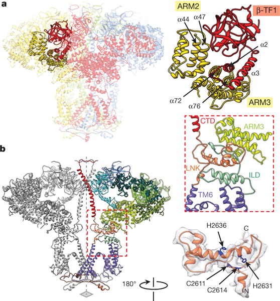
Perhaps the most prominent feature of the cytosolic region of InsP3R1 is the solenoid-like architecture of three α-helical domains (ARM1–ARM3) formed by ensembles of armadillo repeats (Fig. 1 and Extended Data Fig. 4c, d). The modular architecture of the ARM domains in InsP3R1 is particularly amenable for generating different interfaces for recognition and binding of a large set of modulatory proteins whose putative binding sites have been previously identified20 (Extended Data Fig. 4a). Thus, the flexible architecture of the ARM domains probably facilitates propagation of ligand-evoked signals towards the ion-conduction pathway.
The ARM domains constitute peripheral densities of the cytosolic region that form a concave surface around the central helical bundle (Fig. 1c). ARM1 (residues 436–714) is formed by the stacking of five armadillo repeats (Extended Data Fig. 5). The first two armadillo repeats of the ARM1 and preceding two β-TF domains (Fig. 4a–c) constitute the ligand-binding domain (LBD)4–7. The β-TF1 domain (residues 5–225) was termed the InsP3-binding suppressor domain, and β-TF2 (residues 226–435) with two α-helices (residues 436–604) of ARM1 constitutes the InsP3-binding core (IBC) region, also designated as β-IBC and α-IBC subdomains, respectively (Fig. 4a–c and Extended Data Fig. 5). The suppressor domain, β-IBC and α-IBC of each subunit form a triangular structure similar to previously reported crystal structures6,7 (Extended Data Fig. 4b). The four LBDs constitute a cytoplasmic apical density around the CTD bundle (Fig. 4a). The ARM2 (residues 1030–1494) and ARM3 domains (residues 1594–2192) include ten and six armadillo repeats, respectively, and together with the helical domain (residues 715–1029), connect the InsP3-binding domains to the channel-forming region. It is notable, that density in ARM2 is less resolved, suggesting higher structural flexibility (Extended Data Fig. 2c). The entire cytosolic solenoid scaffold in the tetrameric InsP3R1 communicates with the TMDs via the central helical bundle and the ILD (Fig. 1b, c and Supplementary Video 2).
Figure 4. Structural coupling between the CTD and InsP3-binding domains.
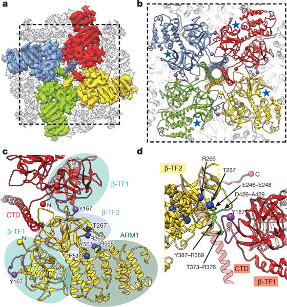
a, Cryo-EM density map of InsP3R1 viewed from the cytosol with LBDs and CTDs colour-coded by subunit. b, InsP3R1 model corresponding to the region marked in a; blue stars denote InsP3-binding sites; purple spheres denote Tyr167. c, Contacts between LBD and CTD of adjacent subunits. Domains are denoted as ellipses colour-coded as in Fig. 1b. Residues involved in InsP3 binding4–7 are rendered as blue spheres. d, The interface between β-TF2 and β-TF1 of neighbouring subunits viewed orthogonally with respect to c. Residues on β-TF2 domain within 5 Å from hotspot loop of β-TF1 are coloured green.
Gating via C- and N-terminal coupling
A functional hallmark of InsP3R channels is the complex interplay between the binding of primary ligands (InsP3 and Ca2+) and channel gating. In addition, several intracellular regulatory molecules interact with InsP3R in a dynamic manner providing functional response in the channel20 (Extended Data Fig. 4a). Our structure suggests that allosteric modulation of InsP3R gating by intracellular signals can occur via several different initiation points that mechanically couple these signals to a common ion-conduction pathway conserved among a large group of ion channels (Extended Data Fig. 7b).
Given the spatial separation between the InsP3-binding and ion-conduction domains within the tetrameric InsP3R1 (Fig. 1c and Extended Data Fig. 8a), there has to be a coupling mechanism for transmission of ligand-evoked signals to the pore to produce a specific gating event. In the crystal structures of the LBD, solved in both the InsP3-bound and apo-states6,7, InsP3 binding at the cleft between the β-IBC and α-IBC domains (Fig. 4b, c) causes closure of the ‘clam-like’ InsP3-binding pocket and movement of the suppressor domain. The intra-subunit interface between the β-TF1 and β-TF2 domains was shown to be dynamic, allowing for β-TF1 to twist in response to InsP3 binding to the IBC6,7. While precise conformational changes associated with InsP3-induced activation of the channel gating in the native tetrameric InsP3R1 are not yet known, these signals may propagate towards the TMDs via discrete intra- and inter-subunit interfaces identified in our structure (Figs 4 and 5). Our structure shows that the helix–turn–helix (α2–turn–α3) motif, probably communicates with the α72 and α76 helices of the ARM3 domain within the adjacent subunit (Fig. 5a and Extended Data Fig. 5). Because the C terminus of the ARM3 domain is connected to the TMD via the ILD, it is conceivable that interactions between the β-TF1 and ARM3 domains will propagate InsP3 evoked conformational changes in the LBD to the pore (Fig. 6a). Importantly, suppressor domain deletion mutants of InsP3R1 have been shown not to exhibit any measurable InsP3-induced Ca2+ release21, emphasizing its critical role in transmitting the InsP3 binding signal. Furthermore, the ARM3 domain contains a putative Ca2+-sensor region (residues 1933–2271), where a highly conserved Glu2101 has been implicated in mediating channel gating22,23. However, no EF-hand Ca2+ binding motif has been found in InsP3R1 (Extended Data Fig. 9).
Figure 5. Cytosolic intra- and inter-subunit interactions.
a, Inter-subunit contacts of β-TF1 with ARM2 and ARM3 domains; subunits are colour-coded. b, Two opposing subunits are viewed along the membrane plane; domains of one subunit are colour-coded. Transmembrane–cytosolic domain interface is indicated with a red dashed line (left), and its close-up view is shown in insert (middle right). The structure of LNK domain is superimposed on cryo-EM densities (bottom right); residues of the C2H2 Zn2+-finger-like motif are coloured blue.
Figure 6. Model for coupling mechanism of InsP3R1 activation by InsP3.
a, Schematic representation of inter-subunit contacts involved in propagation of InsP3-binding signal to the pore (colour-coded by subunit): from β-IBC to CTD/LNK domains and from the suppressor domain (SD) to ARM3/ILD domains of neighbouring subunits. b, The InsP3-induced changes in the LBDs can cause the helices in the cytosolic bundle to rearrange and trigger the motions of the LNKs, that may force the transmembrane bundle to adopt a conformation permeable for Ca2+; colour-coded by subunit.
The β-TF1 domain also forms inter-subunit interactions with β-TF2 and ARM2 domains. The loop of β-TF1 (residues 166–180) is positioned to interact with non-contiguous regions of β-TF2 of the neighbouring subunit including residues 246–248, 373–376, 387–389 and 426–429 (Fig. 4d). Mutation of Tyr167 was shown to impair InsP3-induced Ca2+ release but not affect InsP3 binding to InsP3R1 (ref. 24), suggesting the importance of this inter-subunit interface in signal transmission. Furthermore, the β-TF1 loop (residues 136–139) makes additional inter-subunit contacts with α44 and α47 helices of the ARM2 domain (Fig. 5a), which specifies modulatory activities for InsP3-mediated Ca2+ release25 (Extended Data Fig. 4a). All together, this alludes to the importance of the β-TF1 domain in coupling InsP3 binding to activation of the channel gate. However, our structure shows no direct coupling between the LBD and TM4–5 as previously proposed26, suggesting a more long-range mechanism for signal transmission.
The CTD in InsP3R1 is comprised of a coiled-coil motif, forming a long helical bundle that spans almost the entire cytosolic assembly of the channel, unlike the CTD in ryanodine receptor 1 (RyR1)27–29 (Figs 1c, d, 2c and Extended Data Fig. 8a). The coiled-coil structure is potentially stabilized by a predicted saltbridge between adjacent subunits at residues Gln2700 and Lys2701 (Extended Data Fig. 10a). Furthermore, the CTD of one subunit interacts with the β-TF2 of the adjacent subunit by predominantly inter-domain electrostatic interactions (Fig. 4 and Extended Data Fig. 10b, c). This observation is consistent with earlier biochemical studies of InsP3R proposing that the N-terminal and C-terminal regions are probably in a close association in the native channel30,31. In this arrangement, the cytosolic helical bundle is in a prime position to sense a signal resulting from InsP3 binding and may undergo a conformational change playing a critical role in transmitting the InsP3 signal to the TMDs (Figs 4 and 6).
The CTDs are connected to LNK domains that form a connecting ring between the cytosolic and transmembrane bundles and essentially establish continuous communication between the N-terminal LBDs and the pore-lining TM6 helices (Figs 1c, d and 5b). Noteworthy, the LNK domain of InsP3R1 is structurally analogous to the CTD domain (residues 4957–5037) in RyR1 (refs 21, 32). Both domains contain a Cys2His2 (C2H2) Zn2+-finger motif, although in InsP3R1 there are 16 residues between Cys2614 and His2631 rather than the typical 12 residues (Fig. 5b and Extended Data Fig. 7a). While modulation of the InsP3R channel function has not been investigated regarding its sensitivity to Zn2+, this domain may have a role in coordinating metals that influence channel gating. Mutational studies of the C2H2 residues were shown to either inhibit (Cys2611Ser, Cys2614Ser, His2636Ala) or completely abolish (His2631Ala) channel function, indicating that the LNK domain is positioned to be a crucial structural component for allosteric modulation of channel gating21,32.
This region also contains the sequence (residues 2630–2655) proposed to be essential for InsP3 R tetramerization33 (Extended Data Fig. 7a). A predicted hydrogen bond between Asn2241 and Glu2617 in our structure may bridge the LNK and ILD of neighbouring subunits, possibly having a modest role in channel formation. However, the larger role of the LNK is not entirely evident from our structure given the lack of direct inter-subunit contacts of the LNK domains in the tetrameric InsP3R1 assembly. Rather, the combined interactions throughout the entire central core structure of InsP3R1 may serve to stabilize the tetrameric interfaces providing structural and functional integrity of InsP3R channel (Fig. 6b).
The dominant role of the CTD in transmitting the conformational changes triggered by InsP3 binding to channel gate opening is further supported by an earlier study demonstrating that deletion of 43 residues from the CTD disrupts channel gating26. Furthermore, in a chimaeric channel, comprising the TMD of RyR1 and the cytosolic domains of InsP3R1, the InsP3 efficacy is substantially decreased while InsP3 binding is minimally affected7. It is conceivable that the lack of the InsP3R1 CTD bundle in the chimaeric channel causes uncoupling of InsP3-evoked conformational changes to the channel gating. The unique CTD architecture of InsP3R1 suggests that the two families of Ca2+ release channels explore different mechanisms for transmitting ligand-evoked signals to the ion-permeation pore (Supplementary Discussion). Our hypothetical model for transmission of the InsP3-evoked signal is schematically shown in Fig. 6. Again, while the precise InsP3-induced conformational changes remain to be revealed, the channel activation relies on concerted inter- and intra-domain interactions mediated in the context of the tetrameric InsP3R1 assembly. In this scenario, binding of a single InsP3 molecule to one subunit can trigger a cascade of conformational changes in domains of two neighbouring subunits to propagate the activating signal to the ion-conducting pore.
Conclusion
Here we present the first, to our knowledge, near-atomic resolution structure of a eukaryotic intracellular InsP3-gated Ca2+ release channel purified from rat cerebellum. Our structural analysis reveals conservation of the ion-conduction pore across the tetrameric cation channel family, further suggesting a conserved mechanism for translocation of ions in these channels. However, the control of channel gating in a cellular context is conferred by additional domains that are attached to the pore and contain specific functions, such as voltage-sensing or ligand-binding. The distinctive molecular architecture of these domains defines the nature of work that needs to be performed to convert cellular signals into mechanical gating motion. Thus, while InsP3R1 shares a set of common features with the closely related RyR1 channel, the unique architecture in its C-terminal domain suggests a distinctive allosteric mechanism underlying activation of InsP3R gating (Fig. 6). This mechanism requires direct mechanical coupling between the C terminus and InsP3-binding domains of adjacent subunits and involves rearrangements of the inter-domain interfaces identified in this study. To our knowledge, this is the first structural evidence for the recruitment of the C terminus in gating of the InsP3R channel.
METHODS
Statistical methods for predetermining sample sizes are not appropriate for cryo-EM analysis, which typically involves 104–106 images. Instead, a range of more sophisticated validations and error estimates were performed as described below.
Cryo-EM data acquisition
Detergent-solubilized InsP3R1 was purified from rat cerebellum, and its structure–function integrity has been confirmed as described in our earlier study2. The absence of any channel-specific modulatory proteins has been confirmed using immunoprecipitation/mass spectrometry (data not shown)34. The vitrification of the purified protein was performed as previously described2. Images of frozen-hydrated InsP3R1 particles were acquired on a Technai G2 Polara electron microscope (FEI) operated at 300 kV using a K2 Summit direct electron detector camera (Gatan). Images were collected in dose fractionation super-resolution counting mode at a nominal magnification of ×23,000, corresponding to a calibrated physical pixel size of 1.62 Å and super-resolution pixel size of 0.81 Å. The dose rate on the camera was set to ~10 electrons pixel−1 s−1. The total exposure time was 6 s, leading to a total accumulated dose of 22 electrons Å−2 on the specimen. Each image stack was fractionated into 30 subframes, each with an accumulation time of 0.2 s per frame. Images were acquired at the defocus range of −0.6 to −3.5 μm.
Image processing and 3D reconstruction
Dose-fractionated super-resolution raw image stacks of ice-embedded InsP3R1 were binned 2 × 2 by Fourier cropping resulting in a pixel size of 1.62 Å for further image processing. Each image stack was subjected to motion correction using ‘dosefgpu_driftcorr’35, and a sum of subframes 1–29 in each image stack was used for further image processing (Extended Data Fig. 1). We used ‘e2evalimage.py’ in EMAN 2.1 package to select 3,743 micrographs from a total of 4,160 micrographs for subsequent processing. The signal in the motion-corrected images extends beyond ~4Å (Extended Data Fig. 1b).
156,805 particles were boxed out manually using ‘e2boxer.py’. Image processing was then performed independently in both RELION1.3 and EMAN 2.1 beginning with the same set of boxed out particles. For the RELION1.3 reconstruction, defocus and astigmatism were determined for each micrograph by CTFFIND3 (ref. 36). Our previously published map (EMDB accession 5278) was low pass filtered to 60 Å resolution and used as a starting model for the RELION1.3 refinement. The first refinement yielded subnanometer resolution. After this step, we ran several rounds of iterative 3D classification and 3D auto-refinement to extract the most self-consistent subset of the particle data set. The final map was generated from 96,106 particles.
The EMAN2.1 reconstruction followed standard refinement procedures2,37 with an initial model generated from the current data set with no reference to the prior published structure. On the basis of per-particle SSNR estimates, the best 105,000 particles were included as input to the refinement. During refinement, the worst ~30% of these particles were discarded from each reference-based class-average, based on mutual similarity among particles. Refinement used the EMAN2.1 ‘e2refine_easy’ script, in which most refinement parameters were automatically selected. An initial low resolution refinement was performed using a smaller subset of the data to improve the initial model. As a result of image quality improvement, 2D class-average images generated through iterative image processing exhibit significantly more details than in previous studies2 (Extended Data Fig. 1c).
The particle orientation distribution is not entirely uniform with a broad distribution focused on a ~45° wide distribution near the equator (side views) and another grouping near the top view, along the axis of symmetry (Extended Data Fig. 2d). Given the C4 group symmetry, this distribution includes considerable numbers of particles extending from the equator to the pole, which is sufficient for a complete reconstruction with no missing information.
The final RELION1.3 and EMAN2.1 refinements both used gold standard procedures38,39. In this method, the particle data were split into even/odd numbered halves, and two maps were refined completely independently. The Fourier shell correlation (FSC) 0.143 cut-off was used to estimate the resolution of final 3D reconstructions with a soft auto-mask in RELION post-processing (Extended Data Fig. 2a). RELION1.3 density map was sharpened by applying a B-factor of −256 Å2 that was estimated using an automated procedure40 and visualized with Chimera41. EMAN2.1 maps were automatically filtered as part of the refinement. Local resolution variations were estimated using ResMap42 (Extended Data Fig. 2c).
The resulting 3D reconstructions from the two software packages, RELION1.3 and EMAN2.1, were assessed by computing an FSC between these two maps. Since both maps used the full data set, it is more appropriate to use a 0.25 FSC threshold in this comparison, which corresponds to 2× the SSNR of the 0.143 threshold (Extended Data Fig. 2b). Note, that regardless of localized differences at the highest resolutions, the topology of the two maps is consistent, and the same protein model can be optimized for both maps. All structure/function interpretations would be identical for both maps, irrespective of the resolution value ascribed to the maps.
Model building
Before building a model for the InsP3R1 subunit, secondary structure identification was performed with SSEHunter in Gorgon43,44. A total of 106 helices were identified and a series of β-sheets in the central apical domains of cytosolic region were identified per InsP3R1 subunit. Sequence analysis was then performed on the InsP3R1 primary sequence (GI accession 17380349). As the entire protein was generally too large for most web-based services, serial overlapping sequence segments were used to initially screen the sequence; sequence segments were ~800 amino acids in length and overlapped by ~200 amino acids in either direction. Secondary structure prediction was performed using JPRED345. Analysis of the secondary structure illustrated a predominance of helices, except over the first ~500 amino acids which were indicated to be mainly β-sheet. Deriving the molecular structure of InsP3R1 used a three-pronged approach to generate initial models for different parts of the protein sequence depending on the availability of available crystal structures, fold recognition using homologous structures and completely de novo modelling (Extended Data Fig. 4a). Fold recognition was first performed on the InsP3R1 sequence using PHYRE2 (ref. 46). As expected, the known crystal structures of the N-terminal domains of InsP3R (PDB accessions 3T8S and 3UJ4) were identified spanning residues 7–580. In addition, the structure of the RyR1 N-terminal domain was identified (PDB accession 2XOA). Two structural homologues over residues 1104–1431 were identified; the ARM repeat from 1N4K and an α–α superhelix/ARM repeat (PDB accsesion 1XQR) with 99.7% (25% identity) and 42% (12% sequence identity) confidence, respectively. Models for these domains were obtained directly from the PHYRE2 website (intensive option) and fit to the InsP3R1 density map using UCSF Chimera’s ‘fit in map’ module, EMAN’s Foldhunter and Gorgon44,47. The N-terminal model was localized to LBD and ARM1 regions of the density map. The composite model for residues 1104–1431, containing an α–α superhelix motif, was localized in the ARM2 region of the density map. The secondary structure elements in the models matched well with those identified in the cryo-EM density map, further validating the fit of these structures. Together, these two models accounted for ~33% of the total amino acids in the InsP3R1 subunit. A third homologous domain, the crystal structure of a voltage-gated Na+ channel (PDB accession: 4DXW), was found using PHYRE corresponding to the TMD residues (residues 2278–2605) with 98.7% confidence and ~19% sequence identity. While the structural homologue was fit to the TMD of our InsP3R1 cryo-EM density map, it was not directly used for modelling. The voltage-gated Na+ channel structure was used to confirm the putative InsP3R1 subunit boundaries in the TMD. Modelling of the TMD and the remaining residues were accomplished de novo as described below.
The remainder of the sequence for InsP3R1 was modelled using our previously developed de novo modelling protocol48,49 (Extended Data Fig. 4a). Essentially, we used the aforementioned structural homologues to anchor our sequence assignments. Extending from the ends of the models, we identified the next directly connected secondary structure element via density and/or density skeleton. We then attempted to match the observed SSEHunter secondary structure elements to what was predicted in the primary sequence; the fitted models provided a rough registration of the sequence in the density map, making this process feasible. A Cα backbone model was then constructed for this region using either Gorgon50 or Coot51. The modelling procedure was repeated extending from the previously placed secondary structure elements until either the models merged or encountered a break in the density. It should be noted that model construction was done with the aforementioned 4.7 Å resolution RELION1.3 map, preserving the EMAN2.1 map to act as a control. The Cα backbone model was subsequently verified using our Pathwalking protocol52, which helps to identify alternate backbone topologies. Through this process, less than 15% of the residues were not modelled, likely due to the poor resolvability of the map in those regions (Extended Data Fig. 4a; see main text).
Once a complete Cα backbone model was constructed, the model was transformed into a full atom model using REMO53 and manually adjusted to best fit the density in Coot51. As the density in the transmembrane region was best resolved, model optimization to the density began in the transmembrane regions followed by the remaining regions. From this initial Coot-optimized model, the full-atom model for the tetrameric assembly was then refined with Phenix’s real-space refinement tools as previously described54. In brief, we first used the default real-space refinement settings, followed by subsequent rounds of refinement (~10) incorporating simulated annealing, global minimization, rigid body minimization and local grid searching. After Phenix refinement, the model was again manually adjusted in Coot to best fit the density. This process was iterated over 10 rounds of map-model refinement with Phenix and Coot. As a final test of model fidelity and map agreement, the final model refined against the RELION1.3 map was then in turn refined against the EMAN2.1 map. This resulting refinement gave a nearly identical model with an r.m.s.d. of only 0.8 Å. Inter-and intra-subunit interfaces described here were identified using PDBSum55 and PDBE PISA56.
It should be noted that the de novo modelling process relies on the ability to register sequence predicted helices with those found in the structure. This registration is further enforced by anchoring large, bulky side chains to protruding densities in helices. However, potential errors in the map, modelling and refinement procedures may result in register shifts, non-optimal side-chain placement and tracing errors where there are not sufficient density anchors or where the map is not as well resolved50.
Extended Data
Extended Data Figure 1. Cryo-EM of the purified InsP3R1.
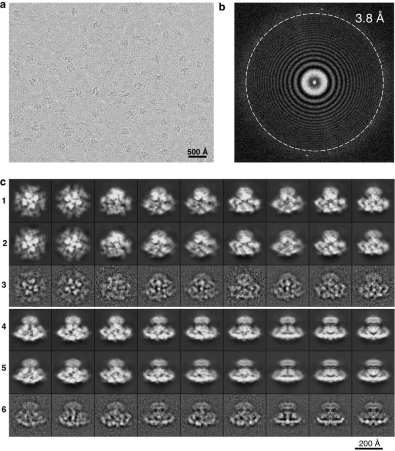
a, Representative electron image of ice-embedded InsP3R1 taken at a defocus of 2.1 μm and recorded using the K2 Summit camera. Shown image is motion-corrected. b, Fourier power spectrum of the micrograph shown in a with Thon rings extending to 3.8 Å. c, 2D projections of the InsP3R1 map from the last iteration of refinement by RELION1.3 (rows 1 and 4) and EMAN2.1 (rows 2 and 5) are shown with corresponding 2D class averages (rows 3 and 6).
Extended Data Figure 2. Resolution estimation of cryo-EM 3D reconstruction.

a, The gold-standard FSC curve for the final cryo-EM 3D reconstruction generated with RELION1.3 (black) and EMAN2.1 (green). The overall resolution is 4.7 Å using the FSC cut-off = 0.143. b, Shown is the FSC curve between the cryo-EM density map generated with RELION1.3 and the molecular model (blue, FSC cut-off is 0.5) and the FSC curve between the 3D reconstructions generated with EMAN2.1 and RELION1.3 (red, FSC cut-off is 0.25). c, The cryo-EM density map of InsP3R1 generated with RELION1.3 is colour-coded based on ResMap (Methods). The map is depicted as viewed along the membrane plane (left) or as a slab of the density (dashed box in left panel) coincident with the four-fold channel axis (right). The cryo-EM density map exhibits local resolution variation ranging from 3.6 Å to 6.5 Å with the most highly resolved densities in the TMD, while parts of the peripheral densities in the cytoplasmic region are of lower resolution. The low resolution peripheral density in the transmembrane region is attributed to detergent bound to the protein. d, Euler angle distribution of all particles used for the final 3D reconstruction. Each view is represented by a sphere, for which the size is proportional to the number of particles for this specific view.
Extended Data Figure 3. 3D cryo-EM density map of the tetrameric InsP3R1 visualized in three orthogonal orientations.
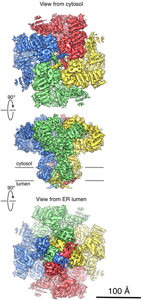
InsP3R1 viewed from the cytosol (top), along the membrane plane (middle) and from the lumen (bottom). Four individual subunits are colour-coded. The map is rendered at a threshold level corresponding to a molecular mass of ~1.3 MDa.
Extended Data Figure 4. Building an atomic model of InsP3R1.
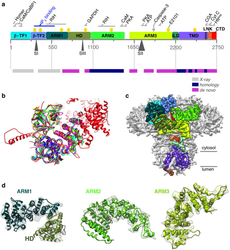
a, Linear representation of a primary structure of InsP3R1 protein (GI accession 17380349). Ten domains identified in the cryo-EM density map are colour-coded. Three sites of alternative splicing (residues 318–332/SI, 918–926/SIII and 1692–1731/SII) are indicated below the sequence bar. Putative binding sites for several channel-specific ligands are indicated above the domains (ATP, ATP-binding CaM/CaBP, calmodulin/Ca2+ binding protein; CGA, chromogranin A; cyt c, cytochrome c; Httexp, huntingtin; PKA, protein kinase A; RIH, RyR/InsP3R homology; yellow circles denote Ca2+-binding20). The panel below shows a linear diagram of the protein sequence colour-coded based on the approach used for modelling different regions in the primary structure. The spaces between the bars correspond to unmodelled sequence (see also Extended Data Fig. 5). b, The structure of the N-terminal domain (NTD) based on cryo-EM density map (red) is shown overlapped with the X-ray crystal structures of NTD (r.m.s.d. values 5 1.3–1.4 Å): 1XZZ (blue); 3T8Sa (cyan); 3T8Sb (green); 3UJ4 (yellow); and 3UJ0 (magenta). c, Cryo-EM density map is viewed along the membrane plane. Densities corresponding to the individual domains of one subunit of InsP3R1 are colour-coded as in a. d, Models for solenoid-like α-helical domains are shown superimposed on their corresponding cryo-EM densities. ARM1–ARM3, armadillo repeat domains1–3; HD, α-helical domain. The densities of ARM2 domain are less resolved than those of ARM1 and ARM3 but are sufficient to trace the backbone.
Extended Data Figure 5. Sequence alignment of selected InsP3R channels.

rInsP3R1, Rattus norvegicus (GI accession 17380349); hInsP3R1, Homo sapiens (GI accession 519668682); hInsP3R2, Homo sapiens (GI accession 259016258); hInsP3R3, Homo sapiens (GI accession 209572633); the primary sequence numbering includes the first methionine. The numbering of residues is given below the sequences, secondary structure elements are indicated above the sequences and colour-coded in correspondence to the domains shown in Fig. 1b; dashed lines indicate regions that were not sufficiently resolved to be modelled. Given the enormous size of InsP3R proteins, the full-length sequence alignment was divided into two panels: sequence alignment for the transmembrane domains is shown in Extended Data Fig. 7a (note, overlap at the loop between the helices α90 and α91).
Extended Data Figure 6. Representative cryo-EM densities.
a–c, The cryo-EM densities for some regions are shown overlaid with the corresponding model: cytosolic helices (a); transmembrane helices (b); the constriction point at Phe2586 within the ion conduction pathway (c), view from the cytosol along the four-fold axis, colour-coded by subunit.
Extended Data Figure 7. Structural conservation of the pore among tetrameric cation channels.
a, Alignment of the channel-forming domains; residues discussed in the text are labelled as following: blue circles, negatively charged residues; red circles, positively charged His2541; yellow highlight, N-glycosylation sites (Asn2476 and Asn2504); green highlight, selectivity filter; blue highlight, conserved Gly2587; green box, hydrophobic constriction region and Phe2586 shown in green; dark blue, Zn2+-finger-like residues Cys2611/Cys2614 and His2631/His2636; blue box, tetramerization region. b, Structural comparison of pore-forming elements of InsP3R1, RyR1, Kv1.2–2.1, NavRh, TRPV1 (PDB accessions: 3J8H, 2R9R, 4DXW and 3J5P, respectively). Note substantial overlap between structures.
Extended Data Figure 8. Comparison of InsP3R1 and RyR1 structures.
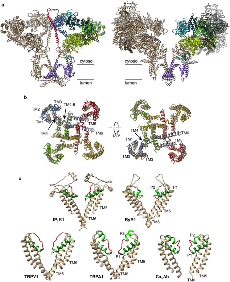
a, Two opposing subunits of InsP3R1 and RyR1 (PDB accession 3J8H) are viewed along the membrane plane. One InsP3R1 subunit is colour-coded by domain (left). Structurally consistent domains in one RyR1 subunit are colour-coded using InsP3R1 domain architecture. Domains of RyR1 not in common are shown in grey. b, TMDs of RyR1 (tan) and InsP3R1 (coloured by subunit) are superimposed using Chimera’s Matchmaker and viewed from the cytosol (left) and lumen (right). The r.m.s.d. between 80 atom pairs is 2.0 Å. For clarity, P-helices are not shown. c, Structural comparison of the selectivity filter (red) in InsP3R1 with that in some tetrameric cation channels: RyR1, TRPV1, TRPA1, CavAb (PDB accessions: 3J8H, 3J5Q, 3J9P and 4MS2, respectively). Two opposing subunits are shown; TM5 and TM6 helices are coloured tan, P-helices are in green.
Extended Data Figure 9. The putative cytosolic Ca2+ sensor in InsP3R1.

a, Cut-open side view of the cryo-EM density map of InsP3R1 is shown with the structures of the Ca2+ sensor region for InsP3R1 (residues 1952–2270) and RyR1 (residues 3877–4251; PDB accession 3J8H); the EF-hand of RyR1 includes residues 4071–4130. b, Close-up view of the overlapped Ca2+ sensor structures for InsP3R1 (colour-coded by domain as in Fig. 1) and RyR1 (tan). The conserved Glu2101/InsP3R1 and Glu4032/RyR1 are shown in red. c, Sequence alignment of the predicted Ca2+ sensor regions comprising the conserved Glu2101/InsP3R1 and Glu4032/RyR1 (red) (rInsP3R1/GI code:17380349; hInsP3R1/GI code: 519668682; hInsP3R2/GI code: 259016258; hInsP3R3/GI code: 209572633; RyR1/GI code: 134134; RyR2/GI code: 308153559; RyR3/GI code: 75074791); green highlight denotes completely conserved residues; yellow highlight denotes identical residues.
Extended Data Figure 10. Structural coupling in the CTD.
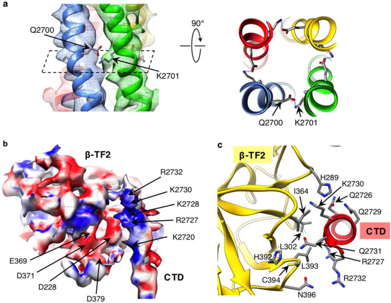
a, A bundle of the CTD helices is viewed perpendicular to the channel axis at the position of a predicted inter-subunit saltbridge between residues Gln2700 and Lys2701. The right panel shows the predicted salt bridge normal to the channel axis. Helices are colour-coded per subunit. b, Structures of the CTD and β-TF2 domains are superimposed on their corresponding cryo-EM densities and the surfaces are colour-coded according to electrostatic charges calculated for the model: blue denotes positive charges; red denotes negative charges. Shown is a side view with the cytoplasmic side facing up. c, Close-up view of the interface between the CTD and β-TF2 domains of two neighbouring subunits; viewed from cytosol perpendicular to the membrane plane.
Supplementary Material
Acknowledgments
We thank S. Murray for his assistance with RELION1.3. This work was supported by grants from the National Institutes of Health (R01GM072804, R21AR063255, S10OD016279, P41GM103832, R01GM079429, R01GM080139 and R21GM100229), the American Heart Association (14RNT1980029), the Muscular Dystrophy Association (295138) and National Science Foundation (DBI-1356306). We gratefully acknowledge the assistance and computing resources provided by the Center for Computational and Integrative Biomedical Research of Baylor College of Medicine and the Texas Advanced Computing Center at the University of Texas at Austin in the completion of this work.
Footnotes
Online Content Methods, along with any additional Extended Data display items and Source Data, are available in the online version of the paper; references unique to these sections appear only in the online paper.
Supplementary Information is available in the online version of the paper.
Author Contributions I.I.S. conceived the project; G.F. and I.I.S. purified and characterized the protein; G.F., Z.W. and I.I.S. performed cryo-EM experiments, including cryospecimen preparation and data acquisition; G.F., Z.W., P.A.S., S.J.L. and I.I.S. analysed data; M.L.B. and M.R.B. built an atomic model; M.L.B., M.R.B., I.I.S. and W.C. interpreted the model; I.I.S., W.C., M.L.B. and M.R.B. wrote a manuscript with contributions from all authors.
Author Information Cryo-EM density map of InsP3R1 has been deposited in the Electron Microscopy Data Bank under accession number EMD-6369. The model coordinates have been deposited in the Protein Data Bank under accession number 3JAV.
The authors declare no competing financial interests. Readers are welcome to comment on the online version of the paper.
References
- 1.Serysheva II, Ludtke SJ. 3D structure of IP3 receptor. Curr Topics Memb. 2010;66C:171–189. doi: 10.1016/S1063-5823(10)66008-5. [DOI] [PubMed] [Google Scholar]
- 2.Ludtke SJ, et al. Flexible architecture of IP3R1 by Cryo-EM. Structure. 2011;19:1192–1199. doi: 10.1016/j.str.2011.05.003. [DOI] [PMC free article] [PubMed] [Google Scholar]
- 3.Murray SC, et al. Validation of cryo-EM structure of IP3R1 channel. Structure. 2013;21:900–909. doi: 10.1016/j.str.2013.04.016. [DOI] [PMC free article] [PubMed] [Google Scholar]
- 4.Bosanac I, et al. Structure of the inositol 1,4,5-trisphosphate receptor binding core in complex with its ligand. Nature. 2002;420:696–700. doi: 10.1038/nature01268. [DOI] [PubMed] [Google Scholar]
- 5.Bosanac I, et al. Crystal structure of the ligand binding suppressor domain of type 1 inositol 1,4,5-trisphosphate receptor. Mol Cell. 2005;17:193–203. doi: 10.1016/j.molcel.2004.11.047. [DOI] [PubMed] [Google Scholar]
- 6.Lin CC, Baek K, Lu Z. Apo and InsP-bound crystal structures of the ligand-binding domain of an InsP receptor. Nature Struct Mol Biol. 2011;18:1172–1174. doi: 10.1038/nsmb.2112. [DOI] [PMC free article] [PubMed] [Google Scholar]
- 7.Seo MD, et al. Structural and functional conservation of key domains in InsP3 and ryanodine receptors. Nature. 2012;483:108–112. doi: 10.1038/nature10751. [DOI] [PMC free article] [PubMed] [Google Scholar]
- 8.Nakagawa T, Okano H, Furuichi T, Aruga J, Mikoshiba K. The subtypes of the mouse inositol 1,4,5-trisphosphate receptor are expressed in a tissue-specific and developmentally specific manner. Proc Natl Acad Sci USA. 1991;88:6244–6248. doi: 10.1073/pnas.88.14.6244. [DOI] [PMC free article] [PubMed] [Google Scholar]
- 9.Nucifora FC, Jr, Li SH, Danoff S, Ullrich A, Ross CA. Molecular cloning of a cDNA for the human inositol 1,4,5-trisphosphate receptor type 1, and the identification of a third alternatively spliced variant. Brain Res Mol Brain Res. 1995;32:291–296. doi: 10.1016/0169-328x(95)00089-b. [DOI] [PubMed] [Google Scholar]
- 10.Danoff SK, et al. Inositol 1,4,5-trisphosphate receptors: distinct neuronal and nonneuronal forms derived by alternative splicing differ in phosphorylation. Proc Natl Acad Sci USA. 1991;88:2951–2955. doi: 10.1073/pnas.88.7.2951. [DOI] [PMC free article] [PubMed] [Google Scholar]
- 11.Doyle DA, et al. The structure of the potassium channel: molecular basis of K+ conduction and selectivity. Science. 1998;280:69–77. doi: 10.1126/science.280.5360.69. [DOI] [PubMed] [Google Scholar]
- 12.Schug ZT, et al. Molecular characterization of the inositol 1,4,5-trisphosphate receptor pore-forming segment. J Biol Chem. 2008;283:2939–2948. doi: 10.1074/jbc.M706645200. [DOI] [PubMed] [Google Scholar]
- 13.Fulton J, Heald S, Badayl Y, Simonson J. Understanding the effects of concentration on the solvation structure of Ca2+ in aqueous solution. I: the perspective on local structure from EXAFS and XANES. J Phys Chem. 2003;107:4688–4696. [Google Scholar]
- 14.Gillespie D, Xu L, Meissner G. Selecting ions by size in a calcium channel: the ryanodine receptor case study. Biophys J. 2014;107:2263–2273. doi: 10.1016/j.bpj.2014.09.031. [DOI] [PMC free article] [PubMed] [Google Scholar]
- 15.Kuo A, et al. Crystal structure of the potassium channel KirBac1.1 in the closed state. Science. 2003;300:1922–1926. doi: 10.1126/science.1085028. [DOI] [PubMed] [Google Scholar]
- 16.Long SB, Campbell EB, Mackinnon R. Crystal structure of a mammalian voltage-dependent Shaker family K+ channel. Science. 2005;309:897–903. doi: 10.1126/science.1116269. [DOI] [PubMed] [Google Scholar]
- 17.Tao X, Avalos JL, Chen J, MacKinnon R. Crystal structure of the eukaryotic strong inward-rectifier K+ channel Kir2.2 at 3.1 Å resolution. Science. 2009;326:1668–1674. doi: 10.1126/science.1180310. [DOI] [PMC free article] [PubMed] [Google Scholar]
- 18.Miyazawa A, Fujiyoshi Y, Unwin N. Structure and gating mechanism of the acetylcholine receptor pore. Nature. 2003;423:949–955. doi: 10.1038/nature01748. [DOI] [PubMed] [Google Scholar]
- 19.Chang G, Spencer RH, Lee AT, Barclay MT, Rees DC. Structure of the MscL homolog from Mycobacterium tuberculosis: a gated mechanosensitive ion channel. Science. 1998;282:2220–2226. doi: 10.1126/science.282.5397.2220. [DOI] [PubMed] [Google Scholar]
- 20.Serysheva II. Toward a high-resolution structure of IP3R channel. Cell Calcium. 2014;56:125–132. doi: 10.1016/j.ceca.2014.08.002. [DOI] [PMC free article] [PubMed] [Google Scholar]
- 21.Uchida K, Miyauchi H, Furuichi T, Michikawa T, Mikoshiba K. Critical regions for activation gating of the inositol 1,4,5-trisphosphate receptor. J Biol Chem. 2003;278:16551–16560. doi: 10.1074/jbc.M300646200. [DOI] [PubMed] [Google Scholar]
- 22.Tu H, et al. Functional and biochemical analysis of the type 1 inositol (1,4,5)-trisphosphate receptor calcium sensor. Biophys J. 2003;85:290–299. doi: 10.1016/S0006-3495(03)74474-9. [DOI] [PMC free article] [PubMed] [Google Scholar]
- 23.Miyakawa T, et al. Ca2+-sensor region of IP3 receptor controls intracellular Ca2+ signaling. EMBO J. 2001;20:1674–1680. doi: 10.1093/emboj/20.7.1674. [DOI] [PMC free article] [PubMed] [Google Scholar]
- 24.Yamazaki H, Chan J, Ikura M, Michikawa T, Mikoshiba K. Tyr-167/Trp-168 in type 1/3 inositol 1,4,5-trisphosphate receptor mediates functional coupling between ligand binding and channel opening. J Biol Chem. 2010;285:36081–36091. doi: 10.1074/jbc.M110.140129. [DOI] [PMC free article] [PubMed] [Google Scholar]
- 25.Soulsby MD, Alzayady K, Xu Q, Wojcikiewicz RJ. The contribution of serine residues 1588 and 1755 to phosphorylation of the type I inositol 1,4,5-trisphosphate receptor by PKA and PKG. FEBS Lett. 2004;557:181–184. doi: 10.1016/s0014-5793(03)01487-x. [DOI] [PubMed] [Google Scholar]
- 26.Schug ZT, Joseph SK. The role of the S4–S5 linker and C-terminal tail in inositol 1,4,5-trisphosphate receptor function. J Biol Chem. 2006;281:24431–24440. doi: 10.1074/jbc.M604190200. [DOI] [PubMed] [Google Scholar]
- 27.Zalk R, et al. Structure of a mammalian ryanodine receptor. Nature. 2015;517:44–49. doi: 10.1038/nature13950. [DOI] [PMC free article] [PubMed] [Google Scholar]
- 28.Yan Z, et al. Structure of the rabbit ryanodine receptor RyR1 at near-atomic resolution. Nature. 2015;517:50–55. doi: 10.1038/nature14063. [DOI] [PMC free article] [PubMed] [Google Scholar]
- 29.Efremov RG, Leitner A, Aebersold R, Raunser S. Architecture and conformational switch mechanism of the ryanodine receptor. Nature. 2015;517:39–43. doi: 10.1038/nature13916. [DOI] [PubMed] [Google Scholar]
- 30.Boehning D, Joseph SK. Direct association of ligand-binding and pore domains in homo- and heterotetrameric inositol 1,4,5-trisphosphate receptors. EMBO J. 2000;19:5450–5459. doi: 10.1093/emboj/19.20.5450. [DOI] [PMC free article] [PubMed] [Google Scholar]
- 31.Yoshikawa F, Iwasaki H, Michikawa T, Furuichi T, Mikoshiba K. Trypsinized cerebellar inositol 1,4,5-trisphosphate receptor. Structural and functional coupling of cleaved ligand binding and channel domains. J Biol Chem. 1999;274:316–327. doi: 10.1074/jbc.274.1.316. [DOI] [PubMed] [Google Scholar]
- 32.Bhanumathy C, da Fonseca PC, Morris EP, Joseph SK. Identification of functionally critical residues in the channel domain of inositol trisphosphate receptors. J Biol Chem. 2012;287:43674–43684. doi: 10.1074/jbc.M112.415786. [DOI] [PMC free article] [PubMed] [Google Scholar]
- 33.Galvan DL, Mignery GA. Carboxyl-terminal sequences critical for inositol 1,4,5-trisphosphate receptor subunit assembly. J Biol Chem. 2002;277:48248–48260. doi: 10.1074/jbc.M209990200. [DOI] [PubMed] [Google Scholar]
- 34.Malovannaya A, et al. Streamlined analysis schema for high-throughput identification of endogenous protein complexes. Proc Natl Acad Sci USA. 2010;107:2431–2436. doi: 10.1073/pnas.0912599106. [DOI] [PMC free article] [PubMed] [Google Scholar]
- 35.Li X, et al. Electron counting and beam-induced motion correction enable near-atomic-resolution single-particle cryo-EM. Nature Methods. 2013;10:584–590. doi: 10.1038/nmeth.2472. [DOI] [PMC free article] [PubMed] [Google Scholar]
- 36.Mindell JA, Grigorieff N. Accurate determination of local defocus and specimen tilt in electron microscopy. J Struct Biol. 2003;142:334–347. doi: 10.1016/s1047-8477(03)00069-8. [DOI] [PubMed] [Google Scholar]
- 37.Tang G, et al. EMAN2: an extensible image processing suite for electron microscopy. J Struct Biol. 2007;157:38–46. doi: 10.1016/j.jsb.2006.05.009. [DOI] [PubMed] [Google Scholar]
- 38.Henderson R, et al. Outcome of the first electron microscopy validation task force meeting. Structure. 2012;20:205–214. doi: 10.1016/j.str.2011.12.014. [DOI] [PMC free article] [PubMed] [Google Scholar]
- 39.Scheres SH, Chen S. Prevention of overfitting in cryo-EM structure determination. Nature Methods. 2012;9:853–854. doi: 10.1038/nmeth.2115. [DOI] [PMC free article] [PubMed] [Google Scholar]
- 40.Rosenthal PB, Henderson R. Optimal determination of particle orientation, absolute hand, and contrast loss in single-particle electron cryomicroscopy. J Mol Biol. 2003;333:721–745. doi: 10.1016/j.jmb.2003.07.013. [DOI] [PubMed] [Google Scholar]
- 41.Pettersen EF, et al. UCSF Chimera–a visualization system for exploratory research and analysis. J Comput Chem. 2004;25:1605–1612. doi: 10.1002/jcc.20084. [DOI] [PubMed] [Google Scholar]
- 42.Kucukelbir A, Sigworth FJ, Tagare HD. Quantifying the local resolution of cryo-EM density maps. Nature Methods. 2014;11:63–65. doi: 10.1038/nmeth.2727. [DOI] [PMC free article] [PubMed] [Google Scholar]
- 43.Baker ML, et al. Modeling protein structure at near atomic resolutions with Gorgon. J Struct Biol. 2011;174:360–373. doi: 10.1016/j.jsb.2011.01.015. [DOI] [PMC free article] [PubMed] [Google Scholar]
- 44.Jiang W, Baker ML, Ludtke SJ, Chiu W. Bridging the information gap: computational tools for intermediate resolution structure interpretation. J Mol Biol. 2001;308:1033–1044. doi: 10.1006/jmbi.2001.4633. [DOI] [PubMed] [Google Scholar]
- 45.Cole C, Barber JD, Barton GJ. The Jpred 3 secondary structure prediction server. Nucleic Acids Res. 2008;36:W197–W201. doi: 10.1093/nar/gkn238. [DOI] [PMC free article] [PubMed] [Google Scholar]
- 46.Kelley LA, Sternberg MJ. Protein structure prediction on the Web: a case study using the Phyre server. Nature Protocols. 2009;4:363–371. doi: 10.1038/nprot.2009.2. [DOI] [PubMed] [Google Scholar]
- 47.Abeysinghe S, Baker ML, Chiu W, Ju T. Semi-isometric registration of line features for flexible fitting of protein structures. Comput Graph Forum. 2010;29:2243–2252. doi: 10.1111/j.1467-8659.2010.01813.x. [DOI] [PMC free article] [PubMed] [Google Scholar]
- 48.Baker ML, Baker MR, Hryc CF, Dimaio F. Analyses of subnanometer resolution cryo-EM density maps. Methods Enzymol. 2010;483:1–29. doi: 10.1016/S0076-6879(10)83001-0. [DOI] [PMC free article] [PubMed] [Google Scholar]
- 49.Baker ML, Zhang J, Ludtke SJ, Chiu W. Cryo-EM of macromolecular assemblies at near-atomic resolution. Nature Protocols. 2010;5:1697–1708. doi: 10.1038/nprot.2010.126. [DOI] [PMC free article] [PubMed] [Google Scholar]
- 50.Baker ML, Baker MR, Hryc CF, Ju T, Chiu W. Gorgon and pathwalking: macromolecular modeling tools for subnanometer resolution density maps. Biopolymers. 2012;97:655–668. doi: 10.1002/bip.22065. [DOI] [PMC free article] [PubMed] [Google Scholar]
- 51.Emsley P, Lohkamp B, Scott WG, Cowtan K. Features and development of Coot. Acta Crystallogr D. 2010;66:486–501. doi: 10.1107/S0907444910007493. [DOI] [PMC free article] [PubMed] [Google Scholar]
- 52.Baker MR, Rees I, Ludtke SJ, Chiu W, Baker ML. Constructing and validating initial Calpha models from subnanometer resolution density maps with pathwalking. Structure. 2012;20:450–463. doi: 10.1016/j.str.2012.01.008. [DOI] [PMC free article] [PubMed] [Google Scholar]
- 53.Li Y, Zhang Y. REMO: A new protocol to refine full atomic protein models from C-alpha traces by optimizing hydrogen-bonding networks. Proteins. 2009;76:665–676. doi: 10.1002/prot.22380. [DOI] [PMC free article] [PubMed] [Google Scholar]
- 54.Adams PD, et al. PHENIX: a comprehensive Python-based system for macromolecular structure solution. Acta Crystallogr D. 2010;66:213–221. doi: 10.1107/S0907444909052925. [DOI] [PMC free article] [PubMed] [Google Scholar]
- 55.de Beer TA, Berka K, Thornton JM, Laskowski RA. PDBsum additions. Nucleic Acids Res. 2014;42:D292–D296. doi: 10.1093/nar/gkt940. [DOI] [PMC free article] [PubMed] [Google Scholar]
- 56.Krissinel E, Henrick K. Inference of macromolecular assemblies from crystalline state. J Mol Biol. 2007;372:774–797. doi: 10.1016/j.jmb.2007.05.022. [DOI] [PubMed] [Google Scholar]
Associated Data
This section collects any data citations, data availability statements, or supplementary materials included in this article.