Significance
Sorely lacking are techniques to engineer tissue grafts bearing a means to receive adequate blood supply during implantation and after integration with host tissue. Efforts to optimize graft tissue vascularization have manipulated multiple factors but have placed little focus on the role of mechanical forces in blood vessel network assembly. The present work assessed the impact of cell-induced and externally applied forces on the morphology of vessel networks within engineered tissue constructs. Network quality, directly correlated with force intensity and vessel orientation, was tunable by application of different patterns of force. Implantation of grafts bearing networks arranged to match those in the implant site is expected to improve graft integration prospects, as well as their long-term viability and strength.
Keywords: mechanical forces, endothelial cells, vascularization, engineered tissue
Abstract
Understanding the forces controlling vascular network properties and morphology can enhance in vitro tissue vascularization and graft integration prospects. This work assessed the effect of uniaxial cell-induced and externally applied tensile forces on the morphology of vascular networks formed within fibroblast and endothelial cell-embedded 3D polymeric constructs. Force intensity correlated with network quality, as verified by inhibition of force and of angiogenesis-related regulators. Tensile forces during vessel formation resulted in parallel vessel orientation under static stretching and diagonal orientation under cyclic stretching, supported by angiogenic factors secreted in response to each stretch protocol. Implantation of scaffolds bearing network orientations matching those of host abdominal muscle tissue improved graft integration and the mechanical properties of the implantation site, a critical factor in repair of defects in this area. This study demonstrates the regulatory role of forces in angiogenesis and their capacities in vessel structure manipulation, which can be exploited to improve scaffolds for tissue repair.
Techniques to generate vascularized tissues bear significant clinical value in regenerative medicine because they ensure sufficient oxygen and nutrient supply within the host tissue, cardinal to transplant integration and survival (1–7). Recent works have attempted to optimize blood vessel network properties, such as geometry, maturity, and stability, by supplementing cultures with biological factors (8), biomaterials (9), and geometrical constraints (10, 11). Although mechanical forces play a central role in all biological processes and have been demonstrated to influence cell differentiation (12), shape (13), migration (14) and organization (15), they have yet to be comprehensively investigated in relation to vascular network assembly. These forces can include both external forces, in the form of shear stress or tensile and compression forces (16), as well as cell-induced contractile forces (17). Both external tensile forces and cell-induced forces act on the cell cytoskeleton and are mostly transmitted to the cell through the actomyosin pathway, adhesion sites, and cell stress fibers (18). In addition, several studies have reported measurement of cell-induced forces on their substrates (19) but have hardly focused on identifying a correlation between the level of cell-induced force and tubular network organization.
Distinct differences in vascular network morphology exist between tissue types, where, for example, vessels are aligned in parallel to muscle fibers but take on a radial organization in the retinal lumen (20). We hypothesized that tensile forces applied by and on the cells during network assembly play a central role in determining vascular network morphology and properties. Moreover, we hypothesized that implantation of a vascular network organized to match that of the implantation site will improve tissue integration and long-term outcomes. This study monitored the impact of tensile forces on vascular network morphology and properties. Although previous studies primarily examined the effect of such forces on endothelial monolayers or individual cells (21, 22), the present experimental setup used 3D systems and focused on tube formation and vascular network assembly. More specifically, the effect of cyclic and static tensile forces on network morphogenesis in engineered tissue constructs and their effect on tissue integration postimplantation were examined.
Results
Static Tensile Forces Influence Vascular Network Organization and Angiogenesis.
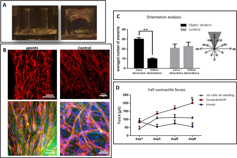
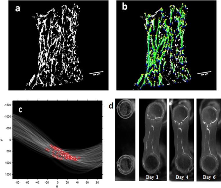
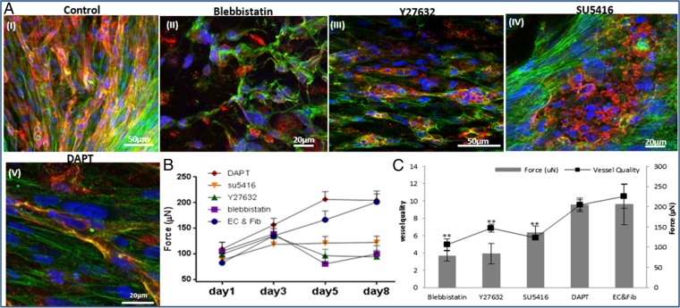
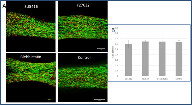
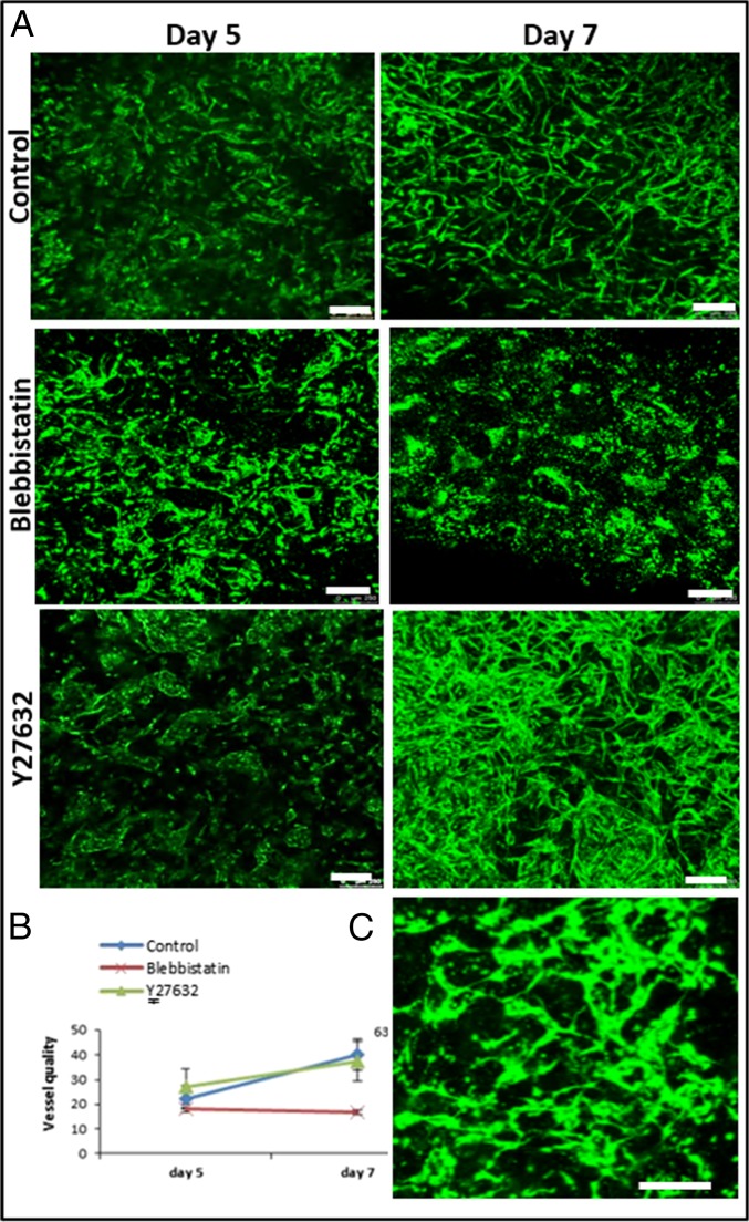
A coculture of fibroblasts and endothelial cells (ECs) was seeded within fibrin gel fabricated uniaxially between two polydimethylsiloxane (PDMS) µposts (Fig. S1A) (23). The visually observed effects were quantified by application of a custom-designed image analysis program, based on the Hough transform function in Matlab, to calculate the orientation of the vessel structures (Fig. S2). The static tensile forces, induced by cellular contractile forces and gel shrinkage, triggered formation of vessel-like structures parallel to the stretching direction, consistent with cell actin fiber orientation (Fig. S1 B and C). On day 8, the highest level of forces (200 µN) was measured in gels embedded with cocultures of ECs and fibroblasts, compared with acellular gels (75 µN) or those containing ECs only (55 µN) (Figs. S1D and S2). The low levels of forces measured in cultures containing ECs only were ascribed to cell-induced gel degradation whereas the slight increase from baseline in forces measured in the cell-free gel on the first three days postseeding was likely due to gel shrinkage. The low levels of forces applied by ECs resonate with other studies that showed that these cells fail to organize into vessels in the absence of supporting cells (24). The involvement of cell contractility in the formation of the vascular network was studied by inhibiting myosin II, a cytoskeletal protein responsible for force transmission within cells. Vessel quality was determined by assessing CD31 levels on day 8 of culture, using a roundness parameter, which rose with object elongation (SI Materials and Methods). Upon addition of the inhibitor, reduced cell-generated forces were observed along with damaged networks, lacking elongated vessel-like structures and actin fibers (Fig. 1 A, II and B). Y27632-mediated inhibition of rho-associated protein kinase (ROCK), an integral mediator of tail retraction, cortical tension, and cell forces, imparted a similar effect (Fig. 1 A, III and B). Cultures treated with SU5416, an endothelial cell-specific inhibitor of the vascular endothelial growth factor (VEGF)-2 receptor (25), displayed reduced network quality whereas fibroblast actin fibers remained straight and aligned. Although the inhibitor had no direct effect on the capacity of the fibroblasts to induce forces, the absence of an intact network resulted in decreased generated force, compared with the control (Fig. 1 A, IV and B). Moreover, DAPT, the γ-secretase inhibitor shown to inhibit Notch signaling (26) and to increase the number of tip cells within the EC population, did not affect total measured force intensity but shortened the time to achieve maximum force by 3 d (day 5 versus day 8 in untreated cells) (Fig. 1 A, V and B). This effect can be attributed to increased angiogenic sprouting induced by the heightened tip cell counts (26). In all of the examined conditions, cell density and viability within the gel were not influenced by the addition of inhibitor (Fig. S3). Measurement of the cell-induced forces generated after cell exposure to external static tensile forces demonstrated a direct correlation between the level of cell-induced forces and network morphology, with a positive correlation between force intensity and vessel elongation (Fig. 1C). We therefore aimed to examine the isolated effect of cell-induced forces on vascular network assembly, without concomitant application of static tensile forces. To this end, blebbistatin and Y26732 were added to 3D polymeric free-floating Gelfoam constructs seeded with EC and fibroblasts. The myosin II inhibitor fully arrested network formation, and vessel quality was lower compared with those within the nontreated scaffold (Fig. 2 A and B). The effect proved reversible because vascular networks began to reform 2 d after removal of blebbistatin (day 9) (Fig. 2C). In contrast, cells retained their ability to form vascular networks in the presence of the ROCK inhibitor Y27632. Unlike its response to conditions of static tensile forces in the fixated fibrin gel, the network of free-floating gels was enriched in the presence of Y27632, compared with the control (Fig. 2 A and B).
Fig. S1.
Coculture of ECs and fibroblasts embedded in a uniaxially fixated fibrin gel. (A) Two PDMS µposts were positioned within a well of a 96-well plate. The fibrin gel is attached to the upper side of the µposts. (B, Upper) CD31-stained HUVEC cells grown within a fixated fibrin gel (Left) or within a free-floating fibrin gel (Right). (Lower) Higher magnification of samples grown as described above and immunofluorescently stained for CD31 (red) and actin (Phalloidin-FITC, green). (C) Orientation analysis of uniaxially fixated fibrin versus control gels. Under conditions of fibrin fixation, most objects were in the zero direction whereas, in the control group, no preferred direction was observed. (D) Measurement of contractile forces exerted by cells embedded within the uniaxially fixated fibrin gel, measured as a function of the deflection of the µpost. *P value < 0.05, **P value < 0.01.
Fig. S2.
Vessel structure orientation and cell force estimation. Vessel orientation was analyzed using Matlab. The threshold was set to the binary image (A), and the image was segmented into objects. By using the Hough transform, lines were detected in the image (B). For each line, an angle (θ) and distance (ρ) from the origin were determined. The line angle distribution between −90 and +90° was then determined (C). The average number of objects in specific angle intervals was then estimated. (D) PDMS µpost deflections during the experiment days. Shown is the top view of the µpost heads.
Fig. 1.
The influence of cytoskeleton and intracellular signaling inhibitors on cell-induced contractile forces and vascular network formation. (A) Immunofluorescence imaging of a uniaxially fixated fibrin gel embedded with a coculture of endothelial cells and fibroblasts and grown for 8 d. Inhibitors were added to the culture medium on day 3 and replaced daily, along with the medium: (I) control gel, (II) gel treated with Blebbistatin, (III) gel treated with Y27632, (IV) gel treated with SU5416, and (V) gel treated with DAPT. Samples were stained to visualize the nuclei (DAPI, blue), endothelial cells (CD31, red), and actin fibers (Phalloidin-FITC, green). (B) Cell-induced contractile forces were measured as a function of µpost deflections of cell-embedded fibrin gels on days 1–8 postseeding. (C) A coplot of vessel quality and cell-induced contractile forces measured on day 8 postseeding.
Fig. S3.
Examining cell density and cell viability in the presence of inhibitors. Live–dead assays were performed on day 5, 2 d after addition of the inhibitor. Constructs were loaded with calcein acetoxymethyl ester (calcein AM;) (1 µmol/L), an indicator of viable cells and ethidium homodimer-1 (4 µmol/L) (Sigma-Aldrich), an indicator of dead cells, for 30 min at 37 °C. Scaffolds were imaged, and viability and cell density were quantified using Matlab (The Mathworks). (A) Fluorescent image of live–dead assay in fibrin gel within the µposts treated with various inhibitors. By estimating the percentage of dead cells in the constructs from the initial seeded number of cells, we received ∼1% dead cells, a suggestion of good and similar viability under all conditions. (B) Quantification of cell density, demonstrating no significant change between the culture conditions.
Fig. 2.
Vascular organization within free-floating scaffolds upon inhibition of cell-generated forces. (A) HUVEC-GFP cells were embedded on a free-floating scaffold that was treated with an inhibitor (blebbistatin/Y27632) on day 3 of culture and later imaged on days 5 and 7. (Scale bars: 250 µm.) (B) Quantification of vessel quality determined by estimating the roundness parameter on days 5 and 7 postseeding. (C) Reformation of vascular networks on day 9, 2 d after removal of blebbistatin. (Scale bars: 250 µm.)
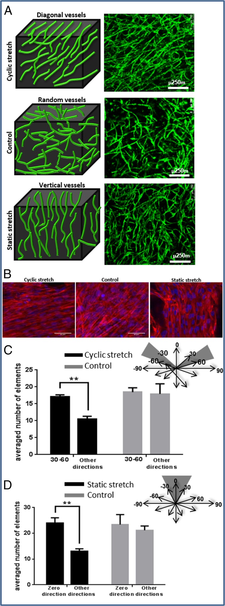
Because previous studies have shown that cyclic tensile forces can affect orientation at the endothelial cellular level (27, 28), we now set out to also examine their effect on vessel network morphology and orientation. To this end, 3D Gelfoam scaffolds cocultured with ECs and fibroblasts for 4 d were exposed to uniaxial cyclic stretching (10% strain and 1-Hz frequency). Vessel-like structures took on a diagonal orientation, symmetrically organized 30–60° to the stretching direction, consistent with the orientation of the cell actin fibers (Fig. 3 A and B). Image analysis performed on day 8, using the Hough transform function, demonstrated more vessels aligned 30–60° to the stretching direction (mean 20 compared with 10 in other directions). In the control group, no favored direction was observed (Fig. 3C). Lumen-like structures were identified in paraffin sections cut perpendicular to the stretching direction, attesting to the formation of tube-like structures (Fig. S4). Static stretch, applied within a self-designed fixation device (Fig. S5), on similar 3D Gelfoam constructs yielded results similar to those observed with the fixated fibrin gel, with vessel orientation parallel to the stretching direction, consistent with the orientation of the cell actin fibers (Fig. 3 A and B).
Fig. 3.
The orientation of vessel-like structures upon exposure to various mechanical stretching regimens. (A) Cyclic stretching applied on uniaxially fixated seeded constructs resulted in diagonal vessels whereas static stretching resulted in vertical vessels, and free-floating scaffolds resulted in randomly orientated vessels. Green, HUVEC-GFP cells. (Scale bars: 250 µm.) The presented images are the projection of about a 500-µm volume. (B) The orientation of cell actin fibers upon exposure to the mechanical forces described in A. Red, phalloidin staining; blue, DAPI. (C) Orientation analysis. Quantification of the average number of objects in 30–60° direction under cyclic stretching and control. (D) Orientation analysis. Quantification of the average number of objects in the stretching direction under static stretching and control.
Fig. S4.
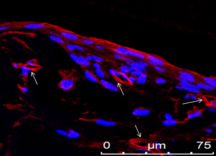
Lumens of vessel-like structures. Paraffin-embedded sections cut perpendicular to the stretching direction contained lumen-like structures, as observed by staining for CD31 (an endothelial marker). Shown is CD31 (red) and DAPI (blue) staining, demonstrating lumens of vessel-like structures, which are marked with arrows.
Fig. S5.
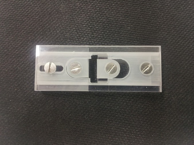
Self-designed fixation device. For applying static tensile forces on cell-seeded 3D scaffold constructs, a fixation device was designed to allow for uniaxial fixation of the scaffold at both sides. The advantages of this device are the small size and portability, which enable imaging of fluorescently labeled cells during the culturing period.
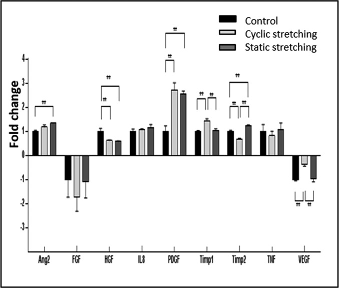
In efforts to characterize factors underlying the differential effects of cyclic versus static tensile forces on vessel orientation, we measured angiogenesis-related cytokine levels after exposure to various mechanical force regimens (Table S1 and Fig. S6). Static stretching induced a significant increase in tissue inhibitor of metalloproteinases (TIMP2), platelet-derived growth factor (PDGF-)-ββ, and angiopoietin-2 (ANG-2) expression levels, suggestive of accelerated network formation (21), whereas cyclic stretching triggered a significant increase in PDGF-ββ, VEGF, and TIMP1 expression levels, but to a decrease in TIMP2 (Fig.4).
Table S1.
Quantification (pg/mol) of secreted angiogenic factors by cells embedded within Gelfoam scaffolds and fibrin gels as estimated with the Q-Plex array chemiluminescent assay
| Examined sample | Ang2 | FGF | HGF | IL8 | PDGF-ββ | TIMP1 | TIMP2 | TNF | VEGF |
| Control Gelfoam | 880.582 | −15.353 | 531.994 | 864.563 | 2.262 | 5,084.963 | 398.651 | 20.485 | −336.008 |
| Cyclic stretching | 1,041.364 | −26.367 | 330.228 | 922.486 | 6.186 | 6,068.235 | 274.112 | 16.809 | −118.243 |
| Static stretching | 1,182.525 | −16.788 | 311.275 | 1,010.105 | 5.818 | 5,345.602 | 499.167 | 21.853 | −324.327 |
| Free-floating fibrin-day 2 | 2,234.360 | 532.745 | 1,102.695 | 1,172.465 | 30.418 | 4,381.490 | 2,257.460 | 36.497 | −122.829 |
| Attached fibrin-day 2 | 2,891.382 | 410.413 | 822.812 | 1,540.140 | 52.958 | 5,057.260 | 7,483.195 | 64.958 | −137.513 |
| Fixated fibrin-day 2 | 2,558.009 | 483.981 | 1,002.798 | 1,760.108 | 38.426 | 5,676.098 | 10,568.202 | 61.013 | −139.572 |
| Free-floating fibrin-day 7 | 1,654.757 | 324.372 | 2,530.675 | 1,454.145 | 34.388 | 4,969.953 | 7,994.456 | 65.847 | −133.553 |
| Attached fibrin-day 7 | 4,485.380 | 203.003 | 7,897.495 | 1,571.455 | 75.672 | 4,583.800 | 12,755.795 | 100.317 | −105.214 |
| Fixated fibrin-day 7 | 2,153.042 | 379.705 | 6,602.625 | 1,760.895 | 37.920 | 5,414.038 | 13,596.653 | 64.772 | −132.187 |
We demonstrate here the quantitative results of cytokine secretions under the different mechanical manipulations. For the fibrin gel, we compared fibrin attached to the plate vs. fixated fibrin in the PDMS µposts vs. free-floating fibrin. The presented results are after subtracting the initial level of the cytokine in the medium.
Fig. S6.
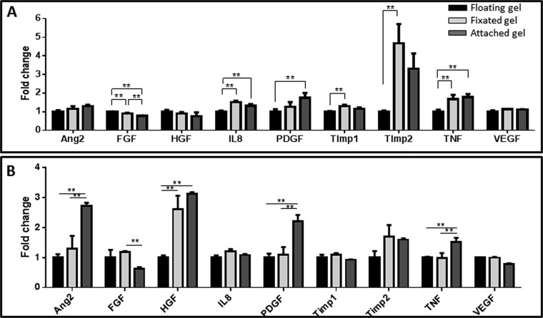
Proangiogenic factor secretion under different mechanical conditions. Protein secretion from fibrin gels measured (A) 2 d or (B) 7 d postseeding. A comparison between free-floating gels (=1), uniaxially fixated gels, and gels attached to a plate. **P value < 0.01. This figure demonstrates the comparison between the different conditions of the fibrin gel in two time points. Attached gel resembles stronger forces than uniaxially fixated gel, all compared with the free-floating control. On day 2, we observed differences in the level of FGF, IL8, PDGF, Timp1, Timp2, and TNF. On day 7, we observed differences in ANG2, FGF, HFG, PDGF, and TNF. Similar to the Gelfoam construct, the level of PDGF increased under the induction of mechanical forces. In addition, the level of ANG2 increased with increasing forces on day 7. However, here, we couldn't identify changes in the level of VEGF.
Fig. 4.
Secretion of angiogenic proteins by cells under the various mechanical stretching regimens. Angiogenesis-related protein secretion from cell-embedded Gelfoam scaffolds grown under cyclic stretching or static stretching conditions. Medium was collected from all samples on day 8 postseeding. Fold change from the control (no stretch) group (=1) is presented. **P value < 0.01.
Orientation of the Vascular Network Improves Integration upon Implantation.
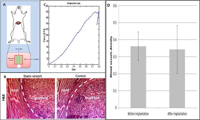
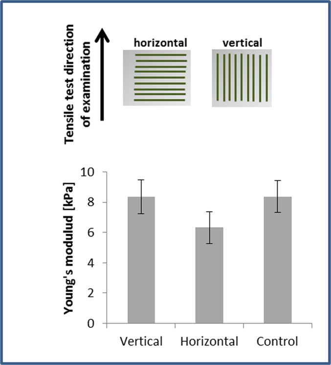
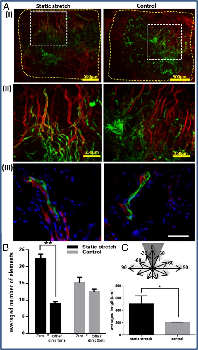
We aimed to evaluate the integration capacity of vessel-like structures designed to mimic the network orientation of the host tissue. To this end, scaffolds subjected to 8 d of static stretching were implanted into the mouse abdominal muscle in the linea-alba region, such that the stretching direction was parallel to the orientation of the mouse muscle fibers (Fig. S7A). Before implantation, no considerable differences were observed in the Young’s modulus of the seeded constructs, when comparing stretching parallel to the aligned vessel direction and orthogonal to the aligned vessel direction. (Fig. S8). H&E staining of the scaffold area within the implantation site (retrieved postimplantation) demonstrated a connection formed between the host tissue and graft fibers (Fig. S7B). Two weeks postimplantation, functional blood vessels of both the host and the implanted vascular network were identified via rhodamine-dextran signals (red) (Fig. 5A). Histological analysis of samples retrieved at this time point (Fig. 5 A, III) demonstrated connections between mouse vessels and implanted human vessels. Moreover, vessel objects preserved their preimplantation orientation within the host (Fig. 5B), and functional vessel-like structures of static-stretched scaffolds were 2.5-fold longer compared with the control group of nonstretched nonoriented vessels (Fig. 5C).
Fig. S7.
In vivo implantation. (A) Implantation of oriented vascular network within mouse abdominal muscle. (B) H&E staining of an implantation site after scaffold retrieval. (C) A typical stress–strain curve of the implantation site after 14 d in vivo. (D) Blood vessel density before and after implantation: The blood vessel density was measured using a self-written Matlab program. No significant change was observed in the vessel density pre- and postimplantation.
Fig. S8.
Young’s modulus of the engineered construct after 7 d of static stretching and preimplantation. Engineered constructs seeded with endothelial cells and fibroblasts and cultured under static stretching conditions were mounted within the Biodynamic test instrument. Scaffolds were stretched along the static stretching direction (vertical, in the direction of the vessel-like structures) and orthogonal to the static stretching direction (horizontal, orthogonal to the vessel-like structures orientation direction). No significant change in Young’s modulus was observed between the vertically and horizontally stretched samples or with the unstretched controls. This suggests that the implanted structures featured similar initial mechanical properties preimplantation and strengthens the hypothesis that mechanical properties improve with better integration with the host tissue.
Fig. 5.
Implantation of static-stretched and control scaffolds in the mouse abdominal muscle. Scaffolds were implanted on day 8 postseeding. Two weeks thereafter, rhodamine-dextran was injected through the mouse tail vein to view functional vessels. (A, I) Fluorescence imaging of HUVEC-GFP cells and of rhodamine-dextran in the retrieved scaffolds. Scaffold area is marked in yellow. (II) A larger magnification of the retrieved scaffolds, showing a connection between the implanted and the host vascular network, as well as functional implanted vessel-like structures. (III) Histological staining of frozen sections of the retrieved scaffold. Green, HUVEC-GFP; red, mouse vessels stained with anti-CD31 antibody; blue, DAPI for nucleic staining. (Scale bar: III, 50 µm.) (B) Orientation analysis of vessel-like structures 2 wk postimplantation. Objects from static-stretched scaffolds preserved their orientation in the zero direction, compared with the control scaffold, where no dominant direction was observed. (C) The mean length of functional implanted vessel-like structures.
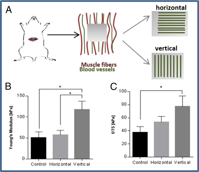
To repair abdominal muscle defects, high stiffness must be achieved at the implantation site, to enable resistance of the high forces with which they are naturally challenged (2). To estimate the impact of oriented vessels on the mechanical properties of the host tissue, the engineered oriented vessel-like structures were implanted in parallel (vertical) vs. perpendicular (horizontal) to the muscle fibers and blood vessels of the host tissue (Fig. 6A). In addition, control grafts, with randomly organized vessels were implanted in a separate group of animals. The tissues with vertically implanted vessels demonstrated higher stiffness and higher ultimate tensile strength (UTS) compared with the control group (Fig. 6 B and C and Fig. S7C). In addition, they displayed higher stiffness compared with horizontally implanted vessels, suggesting that adjustment of the vessel structures to match the orientation of the host tissue vessels improves the functionality and the properties of the resulting tissue.
Fig. 6.
Mechanical analysis of the implantation site postimplantation. (A) Oriented vessels were implanted parallel vs. perpendicular to the vessels of the abdominal tissue. (B) The stiffness (Young’s modulus) and (C) UTS of the tissue 14 d postimplantation, comparing vertical (n = 6), horizontal (n = 4) and control group (n = 4) vessels. *P value < 0.05, **P value < 0.01.
SI Materials and Methods
Cell Culture.
Passages 5–8 of human umbilical vein endothelial cells (HUVECs) (Lonza) and green fluorescent protein-expressing HUVEC (HUVEC-GFP) (Angio-Proteomie) were grown in EGM-2 medium, supplemented with 5% (vol/vol) FBS and endothelial cell growth medium Bulletkit-2 (EGM-2 Bulletkit). Neonatal normal human dermal fibroblasts (NHDFs) (Lonza Walkersville Inc.) were cultured in Dulbecco’s modified Eagle medium (DMEM) (Gibco), supplemented with 10% FBS (HyClone), 1% nonessential amino acids (NEAAs), 0.2% β-mercaptoethanol (Sigma-Aldrich), and 1% penicillin-streptomycin solution (PEN STREP) (Biological Industries). Three dimensional vascular networks were generated by coseeding endothelial cells (HUVEC-GFPs, 3 × 10⁵) and fibroblasts (NHDFs, 0.6 × 10⁵) on 2.3-mm-thick rectangular (5-mm-wide and 5-mm-long) gelatin-based sponges (Gelfoam compressed; Pharmacia & Upjohn Company), incubated in 50% HUVEC-GFP medium and 50% (vol/vol) NHDF medium. Cells were mixed and seeded and then incubated for 40 min before addition of medium. Cocultures of endothelial cells (HUVECs, 1 × 10⁵) and fibroblasts (NHDFs, 0.2 × 10⁵) were also used to create 3D vascular networks within uniaxial fixated or nonfixated fibrin gels. Fibrin-based constructs were created by mixing cells with 50 µL of fibrinogen (1 mg/mL; CALBIOCHEM), followed by addition of 50 µL of thrombin (2 U/mL; CALBIOCHEM).
Mechanical Stimulations.
Cyclic stretching.
Cell-embedded Gelfoam scaffolds were cultured for 4 d in six-well plates and then transferred for another 4 d to the Biodynamic test instrument (Electroforce; Bose), where uniaxial cyclic stretching (triangular protocol) of 10% strain and 1-Hz frequency was applied until day 8. Strain was calculated as change in length divided by initial length of the sample.
Static stretching.
Constructs were fixated within a self-designed fixation device, followed by cell seeding and culture for 8 d (Fig. S1).
Control group.
Cell-embedded constructs were grown in a plate for 8 d.
Static fixation of fibrin gel.
Cell-embedded fibrin gels were created between two PDMS µposts (Myomics) according to the company's protocol. The µposts were imaged every other day to determine µpost deflection and to estimate cell contractile forces.
Control groups included cell-embedded fibrin gels grown within 48-well plates, either attached to the plate or in a free-floating state, from the time of cell seeding.
Immunohistochemistry.
Scaffolds were fixed with 4% (vol/vol) paraformaldehyde (PFA) for 20 min. Whole-construct staining was performed on scaffolds permeabilized with 0.3% Triton X-100 (Bio Lab Ltd), for 10 min at room temperature. Scaffolds were then washed in PBS and immersed overnight in blocking serum [10% (vol/vol) FBS, 0.1% Triton X-100] at 4 °C. Samples were incubated with the monoclonal anti-human CD31 antibody (1:100; Sigma) for 2 h at room temperature, before being treated for 2 h with a Cy3-labeled secondary antibody (1:100; Jackson Immunoresearch Laboratory). For actin fiber staining, TRITC/FITC-phalloidin (1:200; Sigma-Aldrich) was placed over samples for 30 min at room temperature. DAPI (Sigma-Aldrich) was applied for nuclear counterstaining. Implanted constructs were retrieved and fixed with 4% (vol/vol) PFA for 20 min. Scaffolds were maintained overnight in a 30% (vol/vol) sucrose solution and then embedded within optimal cutting temperature compound (Tissue-Tek). Then, 5-μm-thick transverse sections were placed on slides for immunofluorescence and hematoxylin/eosin (H&E) staining.
Construct Imaging and Quantification of Vascularization.
Whole HUVEC-GFP–seeded Gelfoam constructs were imaged using a confocal microscope, imaging a total volume of 500 µm (Leica TCS LSI superzoom macro confocal microscope and Olympus FV10i). Fibrin gels underwent whole-mount staining before being imaged with a confocal microscope (LSM700, Zeiss; or Leica TCS LSI superzoom macro confocal microscope). MATLAB was used to quantify both network quality and vessel-like structure orientation.
Network quality was assessed by estimating the roundness parameter described in Eq. S1 for each element (vessel-like structure) in the image. This parameter is 1 for perfect circle and increases for more elongated elements.
| [S1] |
A self-written algorithm using the Hough transform was used to detect lines within the image and to estimate the orientation of vessel-like structures in respect to the stretching direction (Fig. S2).
For measuring the length of functional vessels, ImageJ was used to draw lines on the vessels that were functional after 14 d in vivo (implanted vessels with rhodamine dextran perfusion).
Estimating Cell-Induced Force According to µPost Deflection.
The moment of inertia of each post was estimated by I = (πR4)/4, where R is the µpost's radius. According to the µpost deflections (δ), length (L) and with a known µpost Young's modulus (E = 1.8 MPa), force was estimated according to:
| [S2] |
The deflection δ was measured by the distance between the two µpost circles using self-written Matlab code that uses the Hough transform for circles.
Inhibition of Cell Contractile Forces and Angiogenesis Elements.
Specific inhibiting factors were added on day 3 postseeding, to both free-floating Gelfoam scaffolds and fixated fibrin gels. The list of inhibitors is as follows: VEGF receptor inhibitor SU5416 (1:1,000, 2.1 mM; Sigma-Aldrich), blebbistatin (50 µM in Gelfoam and 500 µM in fibrin; Sigma-Aldrich), DAPT (1:1,000, 18 mM; Sigma-Aldrich), and Y27632 (1:1,000; TOCRIS).
Proangiogenic Protein Secretion.
Medium was collected at the end of each experiment. The cyclic and static stretching experiments, along with their control groups, contained large volumes of medium, which was reduced by lyophilization, followed by resuspension in a smaller volume suitable for the assay. Cytokine quantification was estimated using the Q-Plex array chemiluminescent assay (Quansys Biosciences), according to the manufacturer's instructions.
In Vivo Implantation.
All animal studies were approved by the Committee on the Ethics of Animal Experiments of the Technion. Athymic nude male mice (7 to 9 wk old; Harlan Laboratories Inc.) were randomly assigned to one of two groups: static-stretched and control scaffolds (three mice per group). Eight days postseeding, static-stretched and control scaffolds were implanted in the abdominal muscle. Mice were anesthetized using a ketamine:xylazine mixture at a dose of 35 μL/20 g, delivered with a 30-gauge needle. A small incision was made allowing access to the linea-alba and surrounding tissue, where a 4-mm-diameter circular wound was created by removing a full-thickness tissue section from the linea-alba. Scaffolds were sutured in place using four 8-0 silk sutures, and the skin area was sutured with 4-0 silk sutures. All mice were monitored closely for 1–2 h, to ensure full recovery from the anesthesia. Mice were anesthetized 2 wk later, and 10 mg/mL rhodamine dextran (Sigma) was perfused through the tail vein. The mice were euthanized, and the graft area was excised, fixed in 10% formalin (Sigma-Aldrich), and imaged immediately thereafter, using a confocal microscope. The length of functional implanted vessels was estimated by measuring the pixels along the length of the functional vessel using ImageJ.
In addition, scaffolds with orientated vessel-like structures were implanted for 14 d in the same region to estimate their influence on the mechanical properties of the host tissue. Three groups were examined: (i) oriented vessels were implanted in parallel (vertical) to the muscle tissue fibers and vessels, (ii), oriented vessels were implanted perpendicular (horizontal) to the muscle tissue fibers and vessels, and (iii) control groups were treated with scaffolds bearing randomly organized vessels. The stiffness (Young's modulus) and ultimate tensile strength (UTS) of the tissue were estimated after 14 d in vivo. A stress–strain curve was generated using the Biodynamic test instrument (Electroforce; Bose), where stress was calculated as the measured force divided by the surface area, and strain was the displacement divided by the tissue initial length. The stiffness was defined as the slope of the linear region in the stress–strain curve and the UTS as the maximum stress in the graph.
Statistical Analysis.
All results are presented as mean ± SEM. Student's t test was used for statistical comparison between two groups, where a P value of <0.05 was considered a significant result.
Discussion
Development of functional and mature blood vessel networks in implantable engineered tissues is fundamental to effective application of tissue engineering techniques toward treatment of a diversity of diseases, such as ischemia and cancer (29, 30). Therefore, much contemporary research focuses on exploring the molecular determinants of the vasculogenesis and angiogenesis processes (31–33). The present study considered the contribution of tensile forces to regulation of formation and overall structure of vascular networks. Three-dimensional polymeric systems seeded with EC and fibroblast cocultures provided the basic conditions necessary for creation of a vessel network. A correlation between the degree of cell-induced contractile forces and the quality of the resulting vessel network was observed. In addition, cyclic and static tensile forces induced distinct effects on network orientation and angiogenic factor secretion. Moreover, organized vascular networks implanted in the mouse abdominal muscle integrated more effectively within the host tissue, compared with nonaligned control samples. Here, we present evidence that the actomyosin pathway, responsible for force generation, with a direct impact on cell shape and tissue remodeling (18, 34–36), guides vascular network assembly. This guidance is achieved via the actin fibers and myosin II, which orient the cells and trigger stretch-induced elongation, respectively (37). Myosin II inhibition resulted in a reversible decrease both in cell forces and in the quality of the resulting network. Moreover, vascular networks formed in fixated gels under ROCK inhibition were impaired, an effect that was not observed in free-floating gels. The dual contribution of ROCK activity to angiogenesis is manifested by tail retraction, leading to enhanced cell migration and further stimulation of angiogenesis, alongside cell cortical tension, resulting in decreased branching and inhibition of angiogenesis (38). Although the role of Myosin II is generally related to cell forces, we further tested response to the inhibitor of ROCK, a protein responsible for mediating cell forces and with a specific role in angiogenesis. In this paper, we present the dual contribution of this inhibitor to the angiogenesis process with and without application of force. Our observations suggest that ROCK activity on a background of cell forces predominantly involves tail retraction and that its inhibition results in decreased migration and damaged vascular networks. In contrast, inhibition of ROCK within the free-floating scaffold results in lower cortical tension, higher branching, and a normal network organization. VEGF is responsible for initiating vessel formation and inducing molecular and cellular events leading to network stabilization and maturation (39). VEGF inhibition in a coculture of ECs and fibroblasts was predicted to damage the network only whereas the level of forces could be maintained by the fibroblasts (19, 40, 41). However, the presented results suggest that the force measured during network assembly is applied by both cell types, which provide a synergistic effect on overall force when collaborating to form elongated tubes. Multicellular organization can be the result of a single cell type driving the orientation of the other cell types or, alternatively, active involvement of both cell types in the orientation process. The current observations imply that both cell types are actively involved in the process because EC damage resulted in decreased forces but had no impact on fibroblast orientation. Furthermore, correlation between the degree of generated force and network quality was also demonstrated upon inhibition of γ-secretase, which did not affect total measured force intensity but shortened the time to achieve maximum force, due to increased angiogenic sprouting induced by the heightened tip cell counts (26). In this study, we demonstrated a means of directing tube assembly using tensile forces, as well as the importance of cell orientation in network structuring. Although other studies have focused on guiding cell orientation using specific patterns or by growing ECs without stromal cell support (11, 42, 43), here, we relied on self-assembly of a coculture of fibroblasts and ECs and observed formation of a stable and mature vascular network, affected only by the applied tensile forces (24, 44). Both static and cyclic forces were examined because they were shown to have differential effects on ECs grown in 2D settings (45). In the present 3D setup, the static forces orientated the cells in the stretching direction whereas the cyclic forces symmetrically oriented the cells 30–60° to the stretching direction, consistent with earlier reports of single-cell observations (46, 47). Importantly, the present model characterized the whole-structure response, and not the single-cell response, to stretching modalities. The contribution of mechanical forces on vascular network morphology and properties can aid in tailoring these responses to match the structure of a desired site of implantation.
Moreover, cyclic stretching was shown to induce a proangiogenic environment, compared with static stretching and the free-floating control. The timing and kinetics of angiogenic factor release (namely, rapid release of VEGF followed by slow release of PDGF-ββ) have been shown to determine network maturity and stabilization (48). In the present experimental setup, VEGF levels were reduced in all configurations, with the highest levels recorded upon cyclic stretching, whereas PDGF-ββ levels increased, with the highest levels measured under cyclic stretching conditions (Fig. 2E). These findings correspond with a report of induced autocrine and paracrine signaling in endothelial and stromal cells subjected to cyclic stretching, followed by up-regulation of Ang-2 and PDGF-ββ protein expression (21).
The understanding that mechanical forces influence the internal structure and overall properties of vascular networks can aid in tailoring them to match the structure of a desired site of implantation. Oriented vessel-like structures implanted in the direction of muscle fibers in the line-alba of abdominal muscle preserved their orientation and contained longer functional vessels compared with the nonstretched control, addressing the need to match the implanted engineered tissue structure with the host tissue structure. No pre- versus postimplantation difference in vessel density was observed (Fig. S7D). In parallel, a previous study performed in our laboratory has shown that prolonged prevascularization of engineered muscle tissue (21 d in vitro) results in improved orientation and integration in vivo (3). Here, application of tensile forces shortened the required prevascularization period to 7 d in vitro. The 2-wk in vivo incubation period was selected because it was previously shown to be sufficient to observe good integration with the host tissue (3). Shorter incubation intervals of 3–4 d in vivo would not be sufficient for examination of the functionality of the implanted vessels. Periods longer than 2 wk may not be able to determine whether such orientation matching can accelerate integration of the implanted tissue with the host tissue. Moreover, these results shed light on the involvement of tensile forces in vascularization and on the mechanism underlying force buildup during network assembly. This work presents a means of achieving vascularized engineered tissues with properties and structures supportive of host tissue function and viability and can be broadened to obtain different arrangements of vascular networks to match those of diverse tissues, such as cardiac, retina, and kidney. We demonstrated both the ability to control tube orientation via manipulation of tensile forces and the efficacy of oriented vascularized tissues in tissue transplantation. Most importantly, this approach monitored tissue structure responses, rather than single-cell responses, enhancing the understanding of coordinated multicellular responses to environmental signals.
Materials and Methods
Detailed materials and methods are in SI Materials and Methods. Briefly, 3D vascular networks were generated by coseeding endothelial cells and fibroblasts on gelatin-based sponges (Gelfoam compressed; Pharmacia & Upjohn Company). Mechanical stimulations were applied on the constructs.
Cyclic Stretching.
Cell-embedded Gelfoam scaffolds were cultured for 4 d and then transferred for another 4 d to the Biodynamic test instrument (Electroforce; Bose), where uniaxial cyclic stretching of 10% strain and 1-Hz frequency was applied. Strain was calculated as change in length divided by initial length of the sample.
Static Stretching.
Constructs were fixated within a self-designed fixation device, followed by cell seeding.
Control Group.
Cell-embedded constructs were grown in a plate.
Cocultures of endothelial cells and fibroblasts were also used to create 3D vascular networks within uniaxial fixated or nonfixated fibrin gels. The cell-embedded fibrin gels were created between two PDMS µposts (Myomics). Control groups included cell-embedded fibrin gels grown within 48-well plates, either attached to the plate or in a free-floating state. Whole human umbilical vein endothelial cell (HUVEC)-green fluorescent protein GFP–seeded Gelfoam constructs and fibrin gels were imaged. Both network quality and vessel-like structure orientation were estimated. Eight days postseeding, static stretched and control scaffolds were implanted in the abdominal muscle of mice. All animal studies were approved by the Committee on the Ethics of Animal Experiments of the Technion.
Acknowledgments
We thank Inbal Michael for help with the cytokine analysis and Yehudit Posen for proofreading the article. The research leading to these results has received funding from the European Research Council (ERC) under the European Union's Seventh Framework Program (FP/2007-2013), ERC Grant Agreement 281501-ENGVASC and Grant Agreement 229294-NanoCard, and was supported in part by the Russell Berrie Nanotechnology Institute at the Technion-Israel Institute of Technology.
Footnotes
The authors declare no conflict of interest.
This article is a PNAS Direct Submission.
This article contains supporting information online at www.pnas.org/lookup/suppl/doi:10.1073/pnas.1522273113/-/DCSupplemental.
References
- 1.Novosel EC, Kleinhans C, Kluger PJ. Vascularization is the key challenge in tissue engineering. Adv Drug Deliv Rev. 2011;63(4-5):300–311. doi: 10.1016/j.addr.2011.03.004. [DOI] [PubMed] [Google Scholar]
- 2.Shandalov Y, et al. An engineered muscle flap for reconstruction of large soft tissue defects. Proc Natl Acad Sci USA. 2014;111(16):6010–6015. doi: 10.1073/pnas.1402679111. [DOI] [PMC free article] [PubMed] [Google Scholar]
- 3.Koffler J, et al. Improved vascular organization enhances functional integration of engineered skeletal muscle grafts. Proc Natl Acad Sci USA. 2011;108(36):14789–14794. doi: 10.1073/pnas.1017825108. [DOI] [PMC free article] [PubMed] [Google Scholar]
- 4.Takebe T, et al. Vascularized and functional human liver from an iPSC-derived organ bud transplant. Nature. 2013;499(7459):481–484. doi: 10.1038/nature12271. [DOI] [PubMed] [Google Scholar]
- 5.Caspi O, et al. Tissue engineering of vascularized cardiac muscle from human embryonic stem cells. Circ Res. 2007;100(2):263–272. doi: 10.1161/01.RES.0000257776.05673.ff. [DOI] [PubMed] [Google Scholar]
- 6.Kaufman-Francis K, Koffler J, Weinberg N, Dor Y, Levenberg S. Engineered vascular beds provide key signals to pancreatic hormone-producing cells. PLoS One. 2012;7(7):e40741. doi: 10.1371/journal.pone.0040741. [DOI] [PMC free article] [PubMed] [Google Scholar]
- 7.Santos MI, Reis RL. Vascularization in bone tissue engineering: Physiology, current strategies, major hurdles and future challenges. Macromol Biosci. 2010;10(1):12–27. doi: 10.1002/mabi.200900107. [DOI] [PubMed] [Google Scholar]
- 8.Chung JC, Shum-Tim D. Neovascularization in tissue engineering. Cells. 2012;1(4):1246–1260. doi: 10.3390/cells1041246. [DOI] [PMC free article] [PubMed] [Google Scholar]
- 9.Lesman A, et al. Engineering vessel-like networks within multicellular fibrin-based constructs. Biomaterials. 2011;32(31):7856–7869. doi: 10.1016/j.biomaterials.2011.07.003. [DOI] [PubMed] [Google Scholar]
- 10.Miller JS, et al. Rapid casting of patterned vascular networks for perfusable engineered three-dimensional tissues. Nat Mater. 2012;11(9):768–774. doi: 10.1038/nmat3357. [DOI] [PMC free article] [PubMed] [Google Scholar]
- 11.Baranski JD, et al. Geometric control of vascular networks to enhance engineered tissue integration and function. Proc Natl Acad Sci USA. 2013;110(19):7586–7591. doi: 10.1073/pnas.1217796110. [DOI] [PMC free article] [PubMed] [Google Scholar]
- 12.Dado-Rosenfeld D, Tzchori I, Fine A, Chen-Konak L, Levenberg S. Tensile forces applied on a cell-embedded three-dimensional scaffold can direct early differentiation of embryonic stem cells toward the mesoderm germ layer. Tissue Eng Part A. 2015;21(1-2):124–133. doi: 10.1089/ten.tea.2014.0008. [DOI] [PMC free article] [PubMed] [Google Scholar]
- 13.Fletcher DA, Mullins RD. Cell mechanics and the cytoskeleton. Nature. 2010;463(7280):485–492. doi: 10.1038/nature08908. [DOI] [PMC free article] [PubMed] [Google Scholar]
- 14.Abu Shah E, Keren K. Mechanical forces and feedbacks in cell motility. Curr Opin Cell Biol. 2013;25(5):550–557. doi: 10.1016/j.ceb.2013.06.009. [DOI] [PubMed] [Google Scholar]
- 15.Krieg M, et al. Tensile forces govern germ-layer organization in zebrafish. Nat Cell Biol. 2008;10(4):429–436. doi: 10.1038/ncb1705. [DOI] [PubMed] [Google Scholar]
- 16.Hoffman BD, Grashoff C, Schwartz MA. Dynamic molecular processes mediate cellular mechanotransduction. Nature. 2011;475(7356):316–323. doi: 10.1038/nature10316. [DOI] [PMC free article] [PubMed] [Google Scholar]
- 17.Balaban NQ, et al. Force and focal adhesion assembly: A close relationship studied using elastic micropatterned substrates. Nat Cell Biol. 2001;3(5):466–472. doi: 10.1038/35074532. [DOI] [PubMed] [Google Scholar]
- 18.DuFort CC, Paszek MJ, Weaver VM. Balancing forces: Architectural control of mechanotransduction. Nat Rev Mol Cell Biol. 2011;12(5):308–319. doi: 10.1038/nrm3112. [DOI] [PMC free article] [PubMed] [Google Scholar]
- 19.Dado D, Levenberg S. Cell-scaffold mechanical interplay within engineered tissue. Semin Cell Dev Biol. 2009;20(6):656–664. doi: 10.1016/j.semcdb.2009.02.001. [DOI] [PubMed] [Google Scholar]
- 20.Milde F, Lauw S, Koumoutsakos P, Iruela-Arispe ML. The mouse retina in 3D: Quantification of vascular growth and remodeling. Integr Biol (Camb) 2013;5(12):1426–1438. doi: 10.1039/c3ib40085a. [DOI] [PMC free article] [PubMed] [Google Scholar]
- 21.Yung YC, Chae J, Buehler MJ, Hunter CP, Mooney DJ. Cyclic tensile strain triggers a sequence of autocrine and paracrine signaling to regulate angiogenic sprouting in human vascular cells. Proc Natl Acad Sci USA. 2009;106(36):15279–15284. doi: 10.1073/pnas.0905891106. [DOI] [PMC free article] [PubMed] [Google Scholar]
- 22.Dickinson LE, Rand DR, Tsao J, Eberle W, Gerecht S. Endothelial cell responses to micropillar substrates of varying dimensions and stiffness. J Biomed Mater Res A. 2012;100(6):1457–1466. doi: 10.1002/jbm.a.34059. [DOI] [PMC free article] [PubMed] [Google Scholar]
- 23.Vandenburgh H, et al. Drug-screening platform based on the contractility of tissue-engineered muscle. Muscle Nerve. 2008;37(4):438–447. doi: 10.1002/mus.20931. [DOI] [PubMed] [Google Scholar]
- 24.Kaully T, Kaufman-Francis K, Lesman A, Levenberg S. Vascularization: The conduit to viable engineered tissues. Tissue Eng Part B Rev. 2009;15(2):159–169. doi: 10.1089/ten.teb.2008.0193. [DOI] [PubMed] [Google Scholar]
- 25.Keskin U, Totan Y, Karadağ R, Erdurmuş M, Aydın B. Inhibitory effects of SU5416, a selective vascular endothelial growth factor receptor tyrosine kinase inhibitor, on experimental corneal neovascularization. Ophthalmic Res. 2012;47(1):13–18. doi: 10.1159/000324994. [DOI] [PubMed] [Google Scholar]
- 26.Hellström M, et al. Dll4 signalling through Notch1 regulates formation of tip cells during angiogenesis. Nature. 2007;445(7129):776–780. doi: 10.1038/nature05571. [DOI] [PubMed] [Google Scholar]
- 27.Ando J, Yamamoto K. Effects of shear stress and stretch on endothelial function. Antioxid Redox Signal. 2011;15(5):1389–1403. doi: 10.1089/ars.2010.3361. [DOI] [PubMed] [Google Scholar]
- 28.Ngu H, et al. Effect of focal adhesion proteins on endothelial cell adhesion, motility and orientation response to cyclic strain. Ann Biomed Eng. 2010;38(1):208–222. doi: 10.1007/s10439-009-9826-7. [DOI] [PubMed] [Google Scholar]
- 29.Losordo DW, Dimmeler S. Therapeutic angiogenesis and vasculogenesis for ischemic disease. Part II. Cell-based therapies. Circulation. 2004;109(22):2692–2697. doi: 10.1161/01.CIR.0000128596.49339.05. [DOI] [PubMed] [Google Scholar]
- 30.Welti J, Loges S, Dimmeler S, Carmeliet P. Recent molecular discoveries in angiogenesis and antiangiogenic therapies in cancer. J Clin Invest. 2013;123(8):3190–3200. doi: 10.1172/JCI70212. [DOI] [PMC free article] [PubMed] [Google Scholar]
- 31.Potente M, Gerhardt H, Carmeliet P. Basic and therapeutic aspects of angiogenesis. Cell. 2011;146(6):873–887. doi: 10.1016/j.cell.2011.08.039. [DOI] [PubMed] [Google Scholar]
- 32.Carmeliet P. Mechanisms of angiogenesis and arteriogenesis. Nat Med. 2000;6(4):389–395. doi: 10.1038/74651. [DOI] [PubMed] [Google Scholar]
- 33.Buschmann I, Schaper W. Arteriogenesis versus angiogenesis: Two mechanisms of vessel growth. News Physiol Sci. 1999;14:121–125. doi: 10.1152/physiologyonline.1999.14.3.121. [DOI] [PubMed] [Google Scholar]
- 34.Kasza KE, Zallen JA. Dynamics and regulation of contractile actin-myosin networks in morphogenesis. Curr Opin Cell Biol. 2011;23(1):30–38. doi: 10.1016/j.ceb.2010.10.014. [DOI] [PMC free article] [PubMed] [Google Scholar]
- 35.Salbreux G, Charras G, Paluch E. Actin cortex mechanics and cellular morphogenesis. Trends Cell Biol. 2012;22(10):536–545. doi: 10.1016/j.tcb.2012.07.001. [DOI] [PubMed] [Google Scholar]
- 36.Munjal A, Lecuit T. Actomyosin networks and tissue morphogenesis. Development. 2014;141(9):1789–1793. doi: 10.1242/dev.091645. [DOI] [PubMed] [Google Scholar]
- 37.Greiner AM, Chen H, Spatz JP, Kemkemer R. Cyclic tensile strain controls cell shape and directs actin stress fiber formation and focal adhesion alignment in spreading cells. PLoS One. 2013;8(10):e77328. doi: 10.1371/journal.pone.0077328. [DOI] [PMC free article] [PubMed] [Google Scholar]
- 38.van Nieuw Amerongen GP, van Hinsbergh VW. Role of ROCK I/II in vascular branching. Am J Physiol Heart Circ Physiol. 2009;296(4):H903–H905. doi: 10.1152/ajpheart.00125.2009. [DOI] [PubMed] [Google Scholar]
- 39.Carmeliet P, Jain RK. Molecular mechanisms and clinical applications of angiogenesis. Nature. 2011;473(7347):298–307. doi: 10.1038/nature10144. [DOI] [PMC free article] [PubMed] [Google Scholar]
- 40.Lesman A, Notbohm J, Tirrell DA, Ravichandran G. Contractile forces regulate cell division in three-dimensional environments. J Cell Biol. 2014;205(2):155–162. doi: 10.1083/jcb.201309029. [DOI] [PMC free article] [PubMed] [Google Scholar]
- 41.Li B, Wang JHC. Fibroblasts and myofibroblasts in wound healing: Force generation and measurement. J Tissue Viability. 2011;20(4):108–120. doi: 10.1016/j.jtv.2009.11.004. [DOI] [PMC free article] [PubMed] [Google Scholar]
- 42.Lai ES, Huang NF, Cooke JP, Fuller GG. Aligned nanofibrillar collagen regulates endothelial organization and migration. Regen Med. 2012;7(5):649–661. doi: 10.2217/rme.12.48. [DOI] [PMC free article] [PubMed] [Google Scholar]
- 43.van der Schaft DW, van Spreeuwel AC, van Assen HC, Baaijens FP. Mechanoregulation of vascularization in aligned tissue-engineered muscle: A role for vascular endothelial growth factor. Tissue Eng Part A. 2011;17(21-22):2857–2865. doi: 10.1089/ten.TEA.2011.0214. [DOI] [PubMed] [Google Scholar]
- 44.Rouwkema J, Rivron NC, van Blitterswijk CA. Vascularization in tissue engineering. Trends Biotechnol. 2008;26(8):434–441. doi: 10.1016/j.tibtech.2008.04.009. [DOI] [PubMed] [Google Scholar]
- 45.Zheng W, Christensen LP, Tomanek RJ. Differential effects of cyclic and static stretch on coronary microvascular endothelial cell receptors and vasculogenic/angiogenic responses. Am J Physiol Heart Circ Physiol. 2008;295(2):H794–H800. doi: 10.1152/ajpheart.00343.2008. [DOI] [PMC free article] [PubMed] [Google Scholar]
- 46.Livne A, Bouchbinder E, Geiger B. Cell reorientation under cyclic stretching. Nat Commun. 2014;5:3938. doi: 10.1038/ncomms4938. [DOI] [PMC free article] [PubMed] [Google Scholar]
- 47.De R, Zemel A, Safran SA. Dynamics of cell orientation. Nat Phys. 2007;3(9):655–659. [Google Scholar]
- 48.Richardson TP, Peters MC, Ennett AB, Mooney DJ. Polymeric system for dual growth factor delivery. Nat Biotechnol. 2001;19(11):1029–1034. doi: 10.1038/nbt1101-1029. [DOI] [PubMed] [Google Scholar]


