Abstract
A 1 × 16 capacitive micro-machined ultrasonic transducer linear array was designed, fabricated, and tested for underwater imaging in the low frequency range. The linear array was fabricated using Si-SOI bonding techniques. Underwater transmission performance was tested in a water tank, and the array has a resonant frequency of 700 kHz, with pressure amplitude 182 dB () at 1 m. The −3 dB main beam width of the designed dense linear array is approximately 5 degrees. Synthetic aperture focusing technique was applied to improve the resolution of reconstructed images, with promising results. Thus, the proposed array was shown to be suitable for underwater imaging applications.
Keywords: capacitive micro-machined ultrasonic transducer linear array, transmission performance, synthetic aperture focusing technique, underwater imaging
1. Introduction
Ultrasound imaging has played an important role in various areas, such as medical diagnosis, medical treatment, nondestructive testing, and ultrasound microscopy [1,2,3]. The ultrasonic transducer is the core component of ultrasound imaging, and currently piezoelectric micro-machined ultrasonic transducers (PMUTs) based on the piezoelectric effect are widely used [4,5]. However, PMUT performance in underwater and medical applications is limited by material properties and impedance matching issues [2,6,7]. Capacitive micro-machined ultrasonic transducers (CMUTs) have many advantages over conventional PMUTs, such as wide bandwidth, high mechanical-electrical conversion efficiency, and ease of integration with electronic circuits to enhance signal-to-noise ratio [2,8,9,10,11,12]. Furthermore, CMUT membranes have low mechanical impedance, which makes them match well with air and other fluid media, and are suitable for manufacturing in large arrays [2,6]. These characteristics promote CMUTs as the development direction for next generation ultrasonic transducers.
Much research has been conducted regarding CMUT structural design, fabrication methods, and implementations. However, most studies have considered high frequency CMUTs (≥3 MHz) for medical imaging applications, with few studies on underwater imaging applications, which require low frequency. Roh et al. used finite element models to design a 1dimensional (1D) CMUT array robust to crosstalk [13]. ChiaHung et al. [14] designed and fabricated an underwater CMUT using full surface micro-machining technique. The transducer operated underwater at approximately 2 MHz with a detection range of 273 mm. Cheng et al. [15] realized B-mode imaging of a metal wire phantom using a 21-element 1-D array with 3.8 MHz central frequency and fractional bandwidth 116% in water, which limited the detection range. Doody et al. [16] designed a CMUT-in-CMOS array, which achieved central frequency 3.5 MHz, fractional bandwidth 32%–44%, and pressure amplitude 181–184 dB () at 15 mm when operated in a water tank. In this work, we designed and fabricated a 1 × 16 CMUT linear array with resonance frequency 700 kHz, and pressure amplitude 182 dB () at 1 m for use in underwater imaging.
2. Structural Design
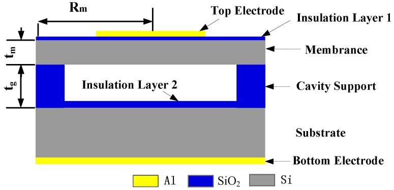
CMUT array elements are composed of multiple sensitive cells connected in parallel. Each cell is composed of electrodes, vibrating membrane, vacuum cavity, insulating layer, and silicon substrate, as shown cross-sectional in Figure 1. A single CMUT array element often cannot meet imaging requirements with its low lateral resolution, low transmission power, and poor directivity. Therefore, a CMUT array composed of N identical elements is used to improve the imaging resolution.
Figure 1.
The structure of a cell.
The natural frequency is one of important performance parameters, whether operating in emission or receiving mode. When CMUTs work in the liquid, the resonant frequency of circular membrane is [17,18]:
| (1) |
where E, , , , , represent the Young’s modulus, the density of membrane, the density of liquid, the Poisson’s ratio, the thickness of the membrane, and the radius of the membrane, respectively. High-resistivity silicon was chosen as the membrane material. From previous finite element software ANSYS analysis [19,20], following Equation (1), and .
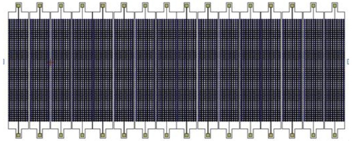
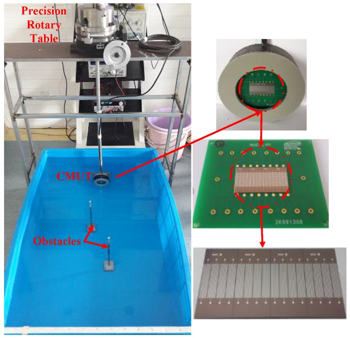
The emission performance of ultrasonic transducers is closely linked with its structural parameters. From previous studies [21], several directivity functions were deduced by Huygens’ Principle to guide the array structure design, and the resultant 1 × 16 CMUT structure is shown in Figure 2.
Figure 2.
The resultant 1 × 16 CMUT array structure.
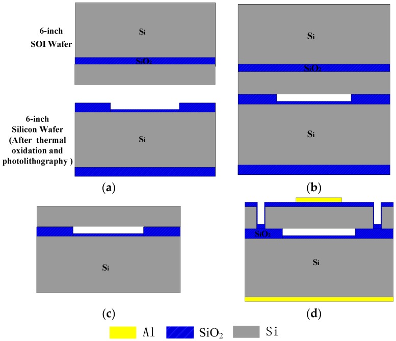
Si-SOI low temperature wafer bonding technology [22,23] was used to fabricate the CMUT linear array (see Figure 3). The silicon wafer was first thermally oxidized, then part-etched to form cavities (tg = 0.8 μm) and an insulation layer (0.15 μm) (Figure 3a). The silicon wafer and SOI wafer were bonded using low temperature bonding (Figure 3b), and the silicon substrate and buried oxide layer of the SOI wafer was eliminated (Figure 3c) to form the silicon membrane (tm = 3.5 μm). Finally, an isolation channel was formed using photolithography and dry etching, and low pressure chemical vapor deposition was used to form a 0.15 μm insulation layer to prevent conductive contact between the top electrodes and the vibration membrane, and evaporation methods were used to form the top electrodes with Al. To ensure fine conductive contact between the bottom electrode and silicon substrate, the other side of the Si wafer had phosphorus ions implanted and metal Al deposited (Figure 3d).
Figure 3.
The main fabrication flow-charts. (a) part etched to form cavities; (b) bonding; (c) form membrane; (d) form isolation channel, insulation layer and electrodes.
3. Underwater Experimental
The CMUT resonant frequency was found as shown in Figure 4. The linear array was encapsulated for insulation from the water [21], and a precision impedance analyzer (Agilent 4294A, Agilent Technologies, Santa Clara, CA, United States) was used to measure the array impedance in water (underwater penetration 0.45 m, water temperature 13 °C). The CMUT resonant frequency = 700 kHz, and electric conductance = 222.35 mS. The CMUT transmission characteristics (transmitting voltage response and directivity) were analyzed over the frequency range of interest (100–1000 kHz).
Figure 4.
Resonant frequency.
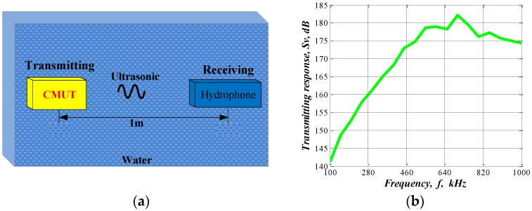
The CMUT transmitting voltage response was measured as shown in Figure 5. A CMUT linear array (transmitter) and a standard hydrophone (receiver) were placed face to face, 1 m apart. The received electrical signal was displayed on an oscilloscope (Agilent 54624A), with direct current (DC) bias 20 V. The CMUT array was driven with a 5 cycle burst signal incorporating 100–1000 kHz and amplitude of 20 Vpp.
Figure 5.
(a) Schematic diagram of the transmitting voltage response experiment; (b) Transmitting response.
The transmitting voltage response can be expressed as [24]:
| (2) |
where l is the distance between the two transducers, is the applied driving voltage of the transmitting CMUT, is the collected voltage standard hydrophone, and is the receiving sensitivity of the hydrophone, the CMUT transmitting voltage response was obtained at different frequencies, as shown Figure 5b. The 1 × 16 CMUT linear array has resonant frequency 700 kHz, and pressure amplitude of 182 dB () at 1 m for underwater applications.
The sector scanning experimental setup is shown in Figure 6. The operating conditions of the CMUT array were the same as previously, except it was now excited with a burst signal at 700 kHz for two cycles. The receiving and transmitting array was fixed on a precision rotary table and rotated to implement sector scanning for two-obstacle imaging.
Figure 6.
Sector scanning configuration.
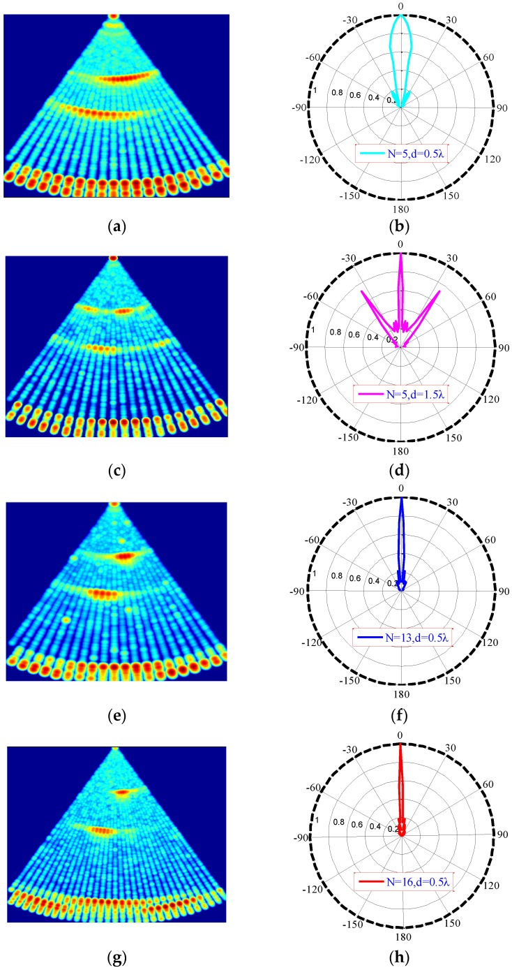
Figure 7 shows the S-scan results and corresponding directivity diagrams for four transmitting conditions Figure 7b,d,f,h, where N is the number of array elements, d is the element spacing between array elements, and λ is the wavelength. The −3 dB main beam width of Figure 7b,d,f,h are approximately 21°, 6.4°, 8°, and 5°, respectively.
Figure 7.
Sector scanning results: (a) N = 5, d = 0.5·; (b) directivity of diagram (a); (c) N = 5, d = 1.5·; (d) directivity of diagram (c); (e) N = 13, d = 0.5·; (f) directivity of diagram (e); (g) N = 16, d = 0.5·; (h) directivity of diagram (g).
-
(1)
For the fixed array element number (Figure 7a,c, or Figure 7b,d), the main lobe becomes sharper as d increases. However, when d > λ [19], strong grating lobes emerge, causing interference in the ultrasound image.
-
(2)
For fixed array length (Figure 7c,e, or Figure 7d,f), the directivity of a dense array is better than that of a sparse array.
-
(3)
For fixed element spacing (Figure 7a,e,g or Figure 7b,f,g), directivity improves as N increases. The wider main lobe also make severe interference.
Thus, N = 16, d = 0.5 was selected as the transmission mode for subsequent underwater imaging.
4. Imaging
To reduce the influence of side lobes and improve the lateral resolution of reconstructed CMUT underwater images, the synthetic aperture focusing technique (SAFT) [25,26,27], an optimization method involving B-scan implemented by delay-and-sum on the received A-scan signals, was applied [28,29].
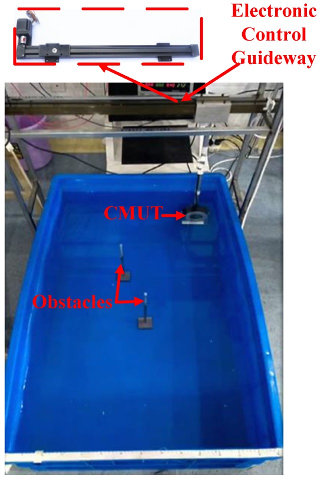
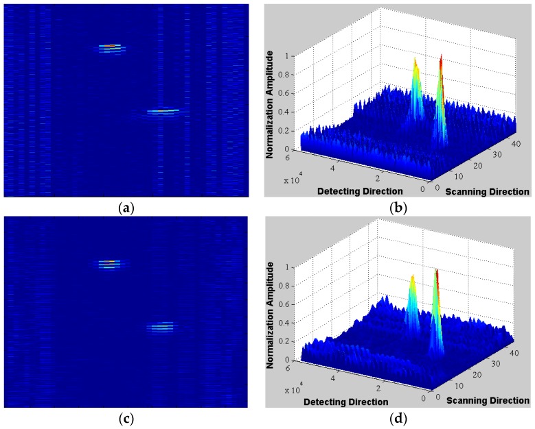
Figure 8 shows the SAFT experimental setup. The operating conditions of the CMUT linear array were the same as for Section 3. The CMUT array was fixed on the electronic control guideway and moved horizontally to implement linear scanning for two-obstacle imaging. 16 elements were simultaneously excited. Figure 9 shows the SAFT reconstructed image (Figure 9a,b) is a significant improvement over traditional B-scan (Figure 9c,d), and artifacts caused by side lobes are effectively suppressed. Thus, the proposed array greatly reduces transmission issues without requiring phased transmission, thereby improving lateral resolution, which will be of great benefit in underwater imaging.
Figure 8.
Linear scanning imaging configuration.
Figure 9.
Reconstructed images (a) B-san reconstructed image; (b) 3-dimensional view of diagram (a); (c) SAFT reconstructed image; (d) 3 dimensional view of diagram (c).
5. Conclusions
A 1 × 16 CMUT array was designed and fabricated for underwater imaging in the low frequency range. The transmission performance of the array was analyzed in a water tank, showing transmission voltage response 182 dB () was achieved at 1 m underwater. Directivity and sector scanning were also analyzed to determine the optimal transmission mode for linear underwater imaging. Significant resolution improvement was obtained by applying SAFT to the received A-scan signals. Thus, the proposed CMUT array shows great benefit for underwater detection applications, such as obstacle avoidance, distance measuring, and imaging.
Acknowledgments
This work was supported by National Science Foundation for Distinguished Young Scholars of China under Grant 61525107, National Natural Science Foundation of China under Grant 61127008 and 61371143, and the “863” program of China under Grant 2013AA09A412.
Author Contributions
The author Rui Zhang designed the CMUT array structure, organized the experiments, performed the data collection and analysis, and drafted the manuscript. Chenyang Xue provided with the funding support. Wendong Zhang and Changde He designed the fabrication process. Jinglong Song completed the processing of the transducer. Yongmei Zhang performed provided the imaging algorithm guide.
Conflicts of Interest
The authors declare no conflict of interest.
References
- 1.Caronti A., Caliano G., Carotenuto R., Savoia A., Pappalardo M., Cianci E., Foglietti V. Capacitive micromachined ultrasonic transducer (CMUT) arrays for medical imaging. Microelectron. J. 2006;37:770–777. doi: 10.1016/j.mejo.2005.10.012. [DOI] [Google Scholar]
- 2.Oralkan O., Ergun A.S., Johnson J.A., Karaman M., Demirci U., Kaviani K., Lee T.H., Khuri-Yakub B.T. Capacitive micromachined ultrasonic transducers: Next-generation arrays for acoustic imaging? IEEE Trans. Ultrason. Ferroelectr. Freq. Control. 2002;49:1596–1610. doi: 10.1109/TUFFC.2002.1049742. [DOI] [PubMed] [Google Scholar]
- 3.Choe J.W., Oralkan O., Nikoozadeh A., Gencel M., Stephens D.N., O'Donnell M., Sahn D.J., Khuri-Yakub B.T. Volumetric Real-Time Imaging Using a CMUT Ring Array. IEEE Trans. Ultrason. Ferroelectr. Freq. Control. 2012;59:1201–1211. doi: 10.1109/TUFFC.2012.2310. [DOI] [PMC free article] [PubMed] [Google Scholar]
- 4.Emadi T.A., Buchanan D.A. A novel 6 × 6 element MEMS capacitive ultrasonic transducer with multiple moving membranes for high performance imaging applications. Sens. Actuators A Phys. 2015;222:309–313. doi: 10.1016/j.sna.2014.11.018. [DOI] [Google Scholar]
- 5.Chang C., Moini A., Nikoozadeh A., Sarioglu A.F., Apte N., Zhuang X., Khuri-Yakub B.T. Singulation for imaging ring arrays of capacitive micromachined ultrasonic transducers. J. Micromech. Microeng. 2014;24:312. doi: 10.1088/0960-1317/24/10/107002. [DOI] [PMC free article] [PubMed] [Google Scholar]
- 6.Wang H., Wang X., He C., Xue C. Design and Performance Analysis of Capacitive Micromachined Ultrasonic Transducer Linear Array. Micromachines. 2014;5:420–431. doi: 10.3390/mi5030420. [DOI] [Google Scholar]
- 7.Ladabaum I., Jin X., Soh H.T., Atalar A., Khuri-Yakub B.T. Surface micromachined capacitive ultrasonic transducers. IEEE Trans. Ultrason. Ferroelectr. Freq. Control. 1998;45:678–690. doi: 10.1109/58.677612. [DOI] [PubMed] [Google Scholar]
- 8.Emadi T.A., Buchanan D.A. Multiple Moving Membrane CMUT with Enlarged Membrane Displacement and Low Pull-Down Voltage. IEEE Electron Device Lett. 2013;34:1578–1580. doi: 10.1109/LED.2013.2286902. [DOI] [Google Scholar]
- 9.Jeong B., Kim D., Hong S. Performance and reliability of new CMUT design with improved efficiency. Sens. Actuators A Phys. 2013;199:325–333. doi: 10.1016/j.sna.2013.06.001. [DOI] [Google Scholar]
- 10.Ergun A.S., Yaralioslu G.G., Khuri-Yakub B.T. Capacitive micromachined ultrasonic Transducers: Theory and technology. J. Aerosp. Eng. 2003;16:76–84. doi: 10.1061/(ASCE)0893-1321(2003)16:2(76). [DOI] [Google Scholar]
- 11.Mills D.M., Smith L.S. Real Time in vivo Imaging with Capacitive Micromachined Ultrasonic Transducer (CMUT) Linear Arrays; Proceedings of the 2003 IEEE Ultrasonic Symposium; Honolulu, HA, USA. 5–8 October 2003; pp. 568–571. [Google Scholar]
- 12.Eccardt P.C., Niederer K., Fischer B. Micromachined Transducers for Ultrasonic Applications; Proceedings of the 1997 IEEE Ultrasonic Symposium; Toronto, ON, Canada. 5–8 October 1997. [Google Scholar]
- 13.Roh Y., Khuri-Yakub B.T. Finite element analysis of underwater capacitor micromachined ultrasonic transducers. IEEE Trans. Ultrason. Ferroelectr. Freq. Control. 2002;49:293–298. doi: 10.1109/58.990939. [DOI] [PubMed] [Google Scholar]
- 14.Liu C., Chen P. Surface micromachined capacitive ultrasonic transducer for underwater imaging. J. Chin. Inst. Eng. 2007;30:447–458. doi: 10.1080/02533839.2007.9671273. [DOI] [Google Scholar]
- 15.Cheng X., Chen J., Li C., Liu J., Shen I., Li P. A Miniature Capacitive Ultrasonic Imager Array. IEEE Sens. J. 2009;9:569–577. doi: 10.1109/JSEN.2009.2013502. [DOI] [Google Scholar]
- 16.Doody C.B., Cheng X., Rich C.A., Lemmerhirt D.F., White R.D. Modeling and Characterization of CMOS-Fabricated Capacitive Micromachined Ultrasound Transducers. J. Microelectromech. Syst. 2011;20:104–118. doi: 10.1109/JMEMS.2010.2093559. [DOI] [Google Scholar]
- 17.Peake W.H., Thurston E.G. The lowest resonant frequency of a water-loaded circular plate. Acoust. Soc. Am. 1954;26:166–168. doi: 10.1121/1.1907302. [DOI] [Google Scholar]
- 18.Wong A.C. Ph.D. Thesis. The University of Michigan; Ann Arbor, MI, USA: 2001. VHF Microelectromechanical Mixer-Filters. [Google Scholar]
- 19.Shen W., Miao J., Xiong J., He C., Xue C. Micro-electro-mechanical systems capacitive ultrasonic transducer with a higher electromechanical coupling coefficient. IET Micro Nano Lett. 2015;10:541–544. [Google Scholar]
- 20.Li Y.P., He C.D., Zhang J.T., Song J.L., Zhang W.D., Xue C.Y. Design and analysis of Capacitive Micromachined Ultrasonic Transducer based on SU-8. Key Eng. Mater. 2014;645–646:577–582. doi: 10.4028/www.scientific.net/KEM.645-646.577. [DOI] [Google Scholar]
- 21.Zhang R., Zhang W.D., He C.D., Song J.L., Mu L.F., Cui J., Zhang Y.M., Xue C.Y. Design of Capacitive Micromachined Ultrasonic Transducer (CMUT) linear array for underwater imaging. Sens. Rev. 2015;36:77–85. doi: 10.1108/SR-05-2015-0076. [DOI] [Google Scholar]
- 22.Song J.L., Xue C.Y., He C.D., Zhang R., Mu L.F., Cui J., Miao J., Liu Y., Zhang W.D. Capacitive Micromachined Ultrasonic Transducers (CMUTs) for Underwater Imaging Applications. Sensors. 2015;15:23205–23217. doi: 10.3390/s150923205. [DOI] [PMC free article] [PubMed] [Google Scholar]
- 23.Zhang R., Xue C.Y., He C.D., Zhang Y.M., Song J.L., Zhang W.D. Design and performance analysis of capacitive micromachined ultrasonic transducer (CMUT) array for underwater imaging. Microsyst. Technol. 2015 doi: 10.1007/s00542-015-2716-z. [DOI] [Google Scholar]
- 24.Zheng S.J., Yuan W.J., Miu R.X., Xue Y.Q. Underwater Acoustic Measurement Testing Technology. Harbin Engineering University Press; Harbin, China: 1995. pp. 223–232. [Google Scholar]
- 25.Neild A., Hutchins D.A., Billson D.R. Imaging using air-coupled polymer-membrane capacitive ultrasonic arrays. Ultrasonics. 2004;42:859–864. doi: 10.1016/j.ultras.2004.01.065. [DOI] [PubMed] [Google Scholar]
- 26.Guarneri G.A., Pipa D.R., Junior F.N., Valéria L., de Arruda R., Victor M., Zibetti W. A Sparse Reconstruction Algorithm for Ultrasonic Images in Nondestructive Testing. Sensors. 2015;15:9324–9343. doi: 10.3390/s150409324. [DOI] [PMC free article] [PubMed] [Google Scholar]
- 27.Skjelvareid M.H., Olofsson T., Birkelund Y., Larsen Y. Synthetic aperture focusing of ultrasonic data from multilayered media using an omega-K algorithm. IEEE Trans. Ultrason. Ferroelectr. Freq. Control. 2011;58:1037–1048. doi: 10.1109/TUFFC.2011.1904. [DOI] [PubMed] [Google Scholar]
- 28.Corl P.D., Grant P.M., Kino G. A Digital Synthetic Focus Acoustic Imaging System for NDE; Proceedings of the 1978 Ultrasonics Symposium; Cherry Hill, NJ, USA. 25–27 September 1978. [Google Scholar]
- 29.Frederick J., Seydel J., Fairchild R. Improved Ultrasonic Nondestructive Testing of Pressure Vessels. Michigan University; Ann Arbor, MI, USA: 1976. Technical Report. [Google Scholar]


