Abstract
A vision-based on-chip sensor for sensing local pressure inside a microfluidic device is proposed and evaluated in this paper. The local pressure is determined from the change of color intensity in the sensing chamber which is pre-filled with colored fluid. The working principle of the sensor is based on polydimethylsiloxane deformation. The pressure at the point of interest is guided into a deformation chamber, where the structural stiffness is softened by chamber geometry, and thus, the chamber deforms as a result of pressure changes. Such deformation is transmitted to the sensing chamber, a same-layer concentric inside the deformation chamber. The deformation in the sensing chamber causes the colored fluid flowing in or out the chamber and leads to different color intensity from the top view through a microscope. Experimental evaluations on static and dynamic responses by regulated input pressures were conducted. The correlation in static response is 0.97 while the dynamic responses are successfully observed up to 16 Hz. The greatest advantage is that the local pressure can be directly seen without any additional hardware or electricity. The whole sensor is on a single-layer microfluidic design, so that the fabrication is simple, consistent, and low-cost. The single-layer design also provides the convenience of easy integration for existing microfluidic systems.
I. INTRODUCTION
Microfluidic system has become popular, because it assists direct and close observation to single cell evaluation, as well as cell culture for biological and medical researches.1,2 The pressure inside a microfluidic chip is essential for many applications. For example, the change of local pressure could alter the results on single cell evaluations.3–5 Cell culture and assembly can also be affected due to different pressure in a microfluidic well.6,7
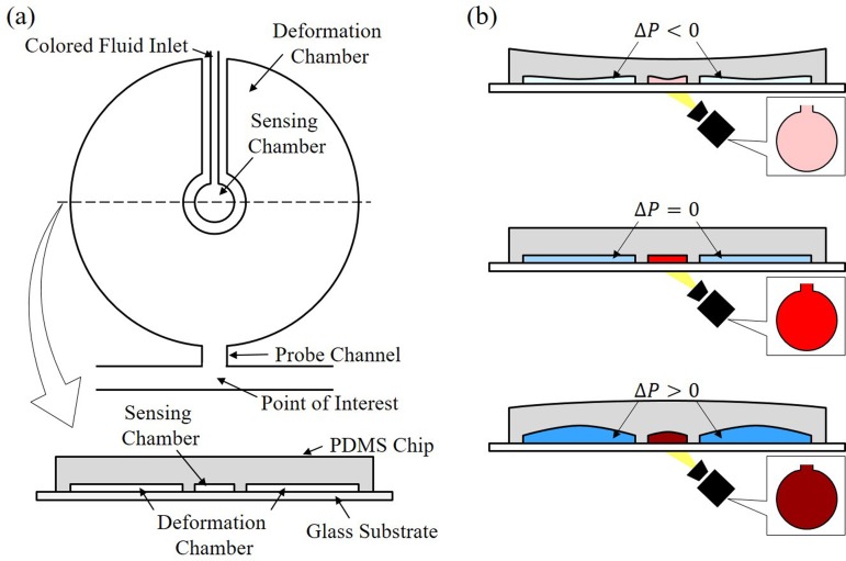
Figure 1 illustrates an overview of the proposed on-chip pressure sensor. Figure 1(a) shows a top view of the sensor and a cross-sectional view along the dashed line. The sensor consists of two concentric chambers, a deformation chamber and a sensing chamber. The deformation chamber is a wide chamber with a large surface area, which softens the structural stiffness of the chamber, and makes it easy to deform.8,9 The chamber is connected to the point of interest by a probe channel as indicated in the top view. The other concentric chamber, the sensing chamber, is located inside the deformation chamber. The sensing chamber is physically separated from the deformation chamber and is only connected with a narrow channel for filling the colored fluid. As shown in the cross-sectional view, both chambers are on the same layer of a polydimethylsiloxane (PDMS) microfluidic chip, which is a common polymer for microfluidic device. Single-layer design provides not only the convenience of chip fabrication but also the consistency of sensor performance.
FIG. 1.
An overview of the proposed on-chip pressure sensor. (a) The sensor includes two concentric chambers on a single-layer design. (b) Color intensity changes with respect to different applied pressure due to PDMS deformation.
Figure 1(b) illustrates the deformation of the chambers under different applied pressures. The applied pressure from the top to the bottom is a negative pressure, a neutral pressure, and a positive pressure, respectively. Since both deformation chamber and sensing chamber are in the same PDMS chip, the sensing chamber passively responds to the surrounding deformation. When the negative pressure is applied from the probe channel as illustrated on the top of Figure 1(b), the sensing chamber shrinks with the deformation chamber. The shrinkage of the sensing chamber pushes out partial colored fluid and results in decreasing of color intensity. On the other hand, when a positive pressure is applied through the probe channel, the deformation chamber will be inflated, and as a result, the color intensity in the sensing chamber increases due to the increase of chamber volume.
Computational simulation using finite element method (FEM) and experiments on fabricated microfluidic chips are performed for evaluating the proposed pressure sensor. The great deformability of the chambers is shown by the simulation which supports the feasibility of the design. Experiments are performed on fabricated sensors with the radii of the deformation chamber and the sensing chamber being and , respectively. A feedback control pressure source is assembled with a commercial pressure sensor and a piezoelectric actuator for providing regulated pressure input. By using a commercial digital camera with 8-bit color depth (from 0 to 255), the color intensity change was obtained around 15 units corresponding to a 90 kPa pressure difference. Dynamic response is tested using the same feedback controlled pressure source with the input pressure amplitude of 50 kPa and the frequencies of 1 Hz, 2 Hz, 4 Hz, 8 Hz, and 16 Hz. All the frequencies are successfully recognized by the values of the color intensity.
The rest of the paper is organized as follows. After a brief review on the related work in Section II, the working principle is presented with computational simulation in Section III. The experiments on both static and dynamic responses are presented in Section IV. Discussions on the results and potential designs are in Section V. Finally, the paper is concluded in Section VI with concluding remarks.
II. RELATED WORKS
Novel approaches of pressure sensing for miniaturized system have been investigated and developed in the last few years. Some approaches are based on detecting the electrical signals resulted from pressure changes. For example, Dai et al. convert capacitance change into frequency output with a ring oscillator.10 Wu et al. developed a two-layer on-chip pressure sensor using a deformable PDMS membrane with ionized fluid.9 The same sensor is later applied to a study of endothelia cells by Liu et al.11 Some other approaches utilize vision-based information for pressure estimation.12 For example, Srivastava and Burns determined microfluidic pressure using the amount of trapped air compression.13 Sessoms et al. estimate the pressure by the moving rate of the droplets inside a microfluidic chip.28 Hosokawa et al. implement gratings on the surface of a PDMS chip and read the pressure by diffractions changes.29 Huang et al. use pressure-sensitive paint for determining the pressure in a microchannel.14 Orth et al. employed deformed PDMS membranes as tunable microlenses for pressure sensing.15 And there are also other different approaches, such as Kim and Daniel measure pressure-induced deformation on the surface of a device using atomic force microscopy.16
Most of these approaches have been applied in application showing their effectiveness on pressure sensing but not all of them are appropriate for PDMS based microfluidic system. For example, trapped air approach cannot be implemented for PDMS microfluidic systems since PDMS has air permeability. For the ones appropriate for PDMS systems, they often require complex fabrication process or high-cost instruments to operate. For example, accurate alignments and membrane tension control are needed for multilayered sensor designs. Directional light source is required for generating consistent diffraction patterns through micro gratings. To the best of the authors' knowledge, the proposed sensor is the first on-chip pressure sensor that fabricated on single layer of PDMS and requires no additional instrument nor electricity. (A microscope and a digital camera are assumed existing in basic microfluidic setup and are not considered as additional instruments.) Preliminary results on the choice of sensing fluid and sensing method were recently presented in conferences proceedings.17,18 This paper is the first comprehensive evaluation on the characteristics of the proposed sensor with both computational simulations and experiments.
III. WORKING PRINCIPLE
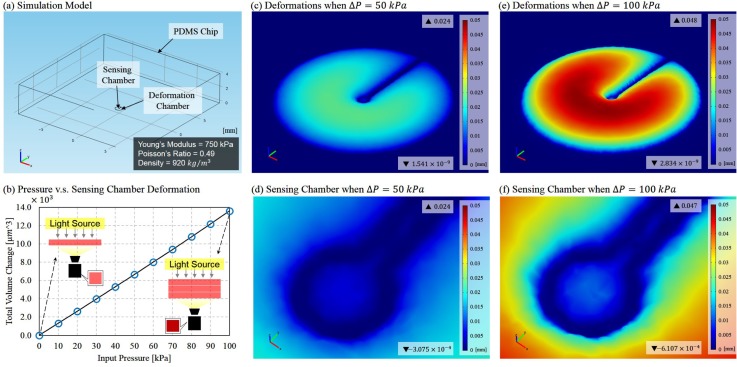
The working principle of the proposed on-chip pressure sensor is based on PDMS deformation, while the PDMS structural stiffness is softened by geometric design with large-surface chambers. Figure 2(a) shows the model used in computational simulation based on the same geometries of the sensor tested in the experiment. The width, length, and height of PDMS chip are and , where the radius of deformation chamber, the radius of sensing chamber, and the depth of the chambers are and , respectively. The simulation is done using a commercial FEM software COMSOL Multiphysics (version 4.0a COMSOL Corp.). PDMS is assumed a linear elastic material with Young's modulus, Poisson ratio, and density of 750 kPa, 0.49, and , respectively. The bottom of the PDMS chip is restrained from deformation since the bottom is always bounded to a substrate glass in an actual chip. The input pressure is only applied inside the deformation chamber as fluid pressure, and the deformation in the sensing chamber is passively occurred due to the deformation transmitted from the deformation chamber. Solid mechanics model is employed for the simulation.
FIG. 2.
FEM simulation results. (a) The model built for the simulation. (b)The relation between the applied pressure and the total deformation over the sensing chamber. (c) The deformation when a pressure of 50 kPa is applied in the deformation chamber. (d) The deformation around the sensing chamber when P = 50 kPa. (e) The deformation when a pressure of 100 kPa is applied in the deformation chamber. (f) The deformation around the sensing chamber when P = 100 kPa.
Figure 2(b) shows the amount of deformation in the sensing chamber with different input pressures in the simulations. The input pressures increase in increments of 10 kPa from 0 kPa to 100 kPa as a relative pressure to a neutral pressure. Since PDMS is considered as a linear elastic material, the results show the expected linear relation which means that the depth of the sensing chamber increases with increase of applied pressure in the deformation chamber. Two illustrations in Figure 2(b) explain how color intensity changes with variation on chamber depth. The color becomes deeper when the chamber depth increases and vice versa.
Figures 2(c)–2(f) show the deformation over the sensor and a close view around the sensing chamber in two cases where the applied pressures are 50 kPa and 100 kPa. The color indicates the amount of displacement on the roof of the chambers corresponding to the color bar on the right. The maximum and minimum values of displacement are shown with straight-up and inverted triangular marks, respectively.
Two remarkable points are observed from the results. First, the deformation chamber is greatly deformed with the pressure of 100 kPa, and the peak of the deformation in the chamber is up to which is about 14 times greater than its original depth . Experimental estimations on PDMS deformation can be found at the supplementary material.24 The second point is that the deformation is mostly happened either in the deformation chamber or the sensing chamber. Only very limited deformation can be seen in the inlet of colored fluid or probe channel. This tells that the PDMS chip only significantly deforms inside the chambers due to softened structural stiffness.
IV. EXPERIMENTS
A. Experimental system
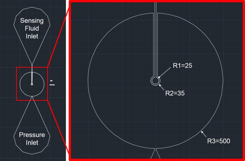
Figure 3 shows the microfluidic design of the chip. Two inlets on the top and bottom are for filling colored fluid and connecting to the pressure source. A closer view of the sensor design is on the right of Fig. 3, where R1, R2, and R3 are the radii in microns for the sensing chamber, inner circle and outer circle of the deformation chamber, respectively.
FIG. 3.
The dimensions of pressure sensor. The pressure inlet is directly connected to the feedback controlled pressure supply, and the sensing fluid is injected from the sensing fluid inlet. The sensing chamber radius, the inner radius and the outer radius of the deformation chamber are represented by R1, R2, and R3, respectively.
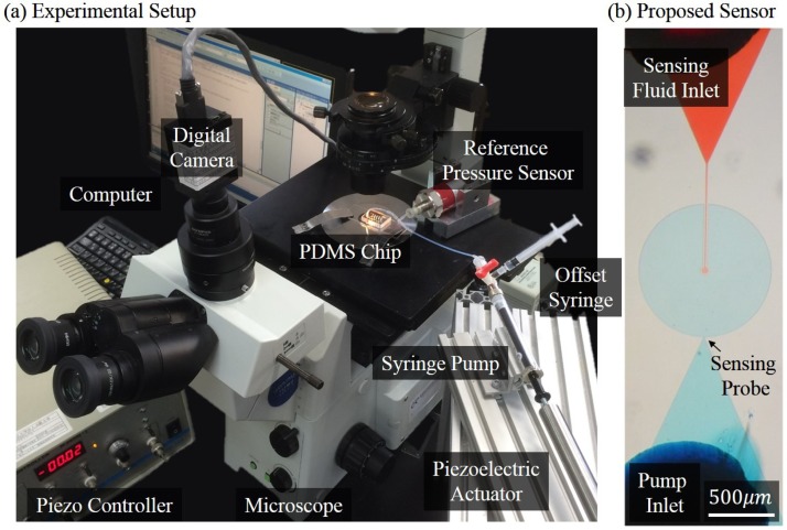
Figure 4(a) shows the experimental system developed for evaluating the proposed on-chip pressure sensor. Three main components in the experimental setup are a feedback controlled pressure source, a vision system, and a PDMS microfluidic chip. The pressure source includes a disposable syringe for adjust pressure offset,25 a glass syringe (SGE Corp.) operated by a piezoelectric actuator (PSt 150/10/200 VS15, Syouei System Co.), and a commercial pressure sensor (FP101A, Copal Electronics Co.). A proportional-integral-derivative (PID) algorithm is implemented on a computer for regulating the output pressure so a specified value of pressure can be applied to the proposed on-chip sensor. The input pressure is used as reference for calibrating the proposed sensor in experiments. The vision system includes a color digital camera (Grasshopper, PointGrey Co.) and a microscope (IX71, Olympus Corp.). The recording rate of the camera is set at 60 frames per second (fps), and each frame is in standard VGA 8-bit format which give color intensity from 0 (lightest) to 255 (deepest).26 Figure 4(b) shows a photo of the fabricated pressure sensor which is a replica from a mold made by standard lithography procedure. The PDMS for the chip is mixed with curing agent at the PDMS-agent ratio of 9:1 and is baked in a oven for 45 min. The cured PDMS chip is bounded to a glass substrate through plasma oxidation. The chambers in Fig. 4(b) are filled with red and blue fluids for clear presentation. The colored fluids are made from edible color powder (Kyoritsu Corp.) and deionized water. The solution is heated and mixed thoroughly to ensure an even solution. The red-color fluid is the same as the sensing fluid used in the experiments.
FIG. 4.
The experimental setup. (a) The system includes the purposed PDMS microfluidic chip, a programmable syringe pump with a commercial pressure sensor, and a digital camera. (b) An image of the proposed sensor.
B. Experimental procedure
The sensing chamber and the deformation chamber are first filled with red colored fluid and water before connecting to the pressure source. Since PDMS is air preamble material, the filling process can be done by simply applying positive pressure from the inlets using a syringe. The positive pressure is kept until no air bubble can be found through the microscope. After the filling process, the pressure inlet is connected to the pressure source, and the sensing fluid inlet is open to the atmosphere.
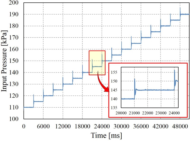
Experiments with static and dynamic pressure inputs were conducted for evaluating the characteristics of the proposed pressure sensor. For evaluating the static responses, pressure was applied to the deformation chamber in increments of 5 kPa from 110 kPa to 195 kPa in absolute pressures as shown in Fig. 5. (The relative pressures are shown in simulation in Sec. III due to the default COMSOL configuration.) The pressure was maintained for 3 s at each increment to make sure the pressure reaches equilibrium, and in the meantime, the color intensity over the sensing chamber was recorded by the camera.27 Considering the average settling time of input pressure is about 200 ms, as the zoom-in plot shown in Fig. 5 and possible delay due to pressure propagation from the reference sensor to the proposed sensor, only the frames within the last second of each step was taken into account for the average color intensity.
FIG. 5.
The input pressure regulated by the feedback system shown in Fig. 4(a).
For the dynamic responses, similar operation was performed except the input pressure being replaced by different frequencies of sinusoidal waves. The input pressure is set 50 kPa and 150 kPa for the amplitude and the mean pressure, which can be represented by
| (1) |
where Pref, f, and t are the input reference pressure, designated frequency, and elapsed time, respectively.
All the recorded videos were later analyzed on Matlab (Mathwork Co.). The average color intensity over the sensing chamber was calculated for pressure determination. Sample videos of the color changing can be found in the supplementary material.24
C. Experimental results
1. Static response
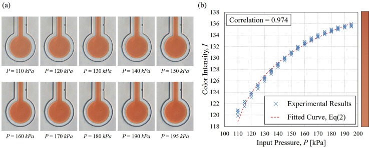
Figure 6 shows the experimental results of the correlation between the input pressures and the average color intensities over the sensing chamber during equilibrium at each pressure increment. The same test was performed five times for examining sensor repeatability. The standard deviations of the color intensities are ranged from 0.17 to 0.39 and have a tendency that a higher pressure has the smaller deviations. The correlation between the average values of color intensity and the applied pressures is 0.97. The relation seems linear between 110 kPa and 150 kPa and becomes nonlinear beyond 150 kPa. A possible interpretation for such a tendency is that the chamber deformation is saturating and thus, the increasing rate of color intensity slowed down. The average values in Fig. 6 were plugged into an exponential function for curve fitting in order to obtain the intensity-pressure conversion function. The choice of exponential function is suggested by the pattern of the results as well as the physical meaning of PDMS such as the saturation of deformation. The least-square algorithm is employed for the fitting, and the fitting result is
| (2) |
where P and I are the converted pressure and color intensity, respectively. The goodness of the fit is evident in the root mean square error RMSE = 1.963 and .
FIG. 6.
Experimental results at static pressures. (a) The raw images of the sensing chamber. Sample videos can be found in the supplementary material.24 (b) The correlation between the input pressure and the average color intensity over the sensing chamber in all five tests.
2. Drift response
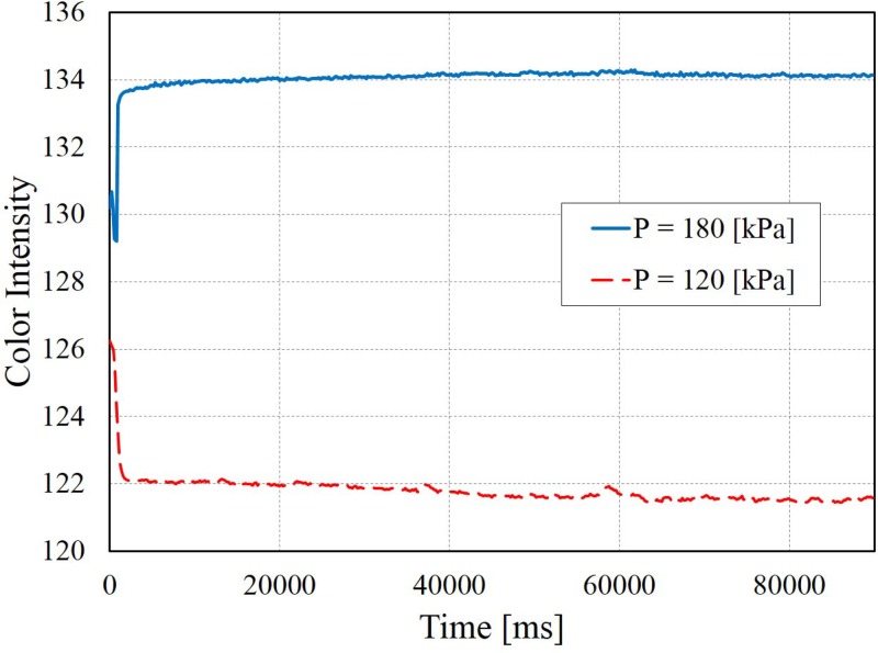
Figure 7 shows the results of drift test. The drift test is another static evaluation for determining the stability of the sensory signal under the same given pressure for a relative longer duration. The input pressures were suddenly increased from 150 kPa to 180 kPa and 120 kPa, and then kept for over one minute. The input pressure is maintained constant within the resolution of the pressure sensor as of . Drifts for both case are observed and are −1.70 and +0.87 for color intensity in the case of the target pressures of P = 120 and P = 180, respectively. The possible causes for the drifts are discussed in Sec. V A.
FIG. 7.
The intensity drift test. Blue and red curves are the results of the step inputs from 150 kPa to 180 kPa and 120 kPa, respectively. The same pressure is maintained for 90 s, and the signal drifts are observed as −1.70 and +0.87 in color intensity.
3. Dynamic response
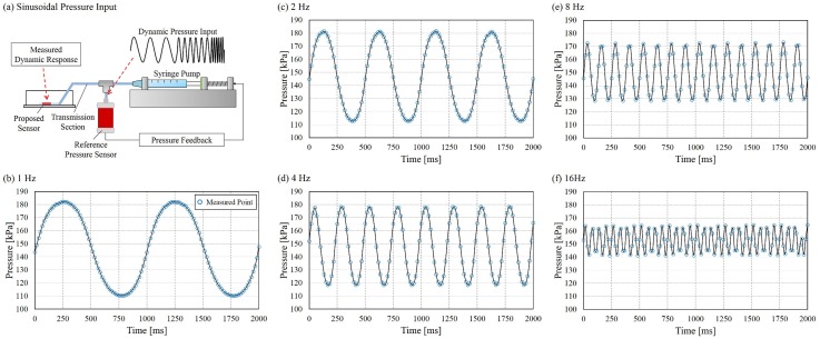
Figure 8 shows an overview of the dynamic results. Figure 8(a) illustrates the relative position between the points of controller-regulate pressure and the proposed sensor. A plastic tube with 60 mm in length and 1 mm in inner diameter was used to connecting the commercial pressure sensor and the PDMS chip as “transmission section” indicated in the figure.
FIG. 8.
The responses of the proposed sensor to dynamic pressure inputs. (a) Illustration of the relative position between sinusoidal pressure inputs and the proposed sensor. (b) f = 1 Hz, (c) f = 2 Hz, (d) f = 4 Hz, (e) f = 8 Hz, (f) f = 16 Hz.
Figures 8(b)–8(f) show the converted pressure sensed by the proposed sensor under sinusoidal inputs. The conversion is done using Eq. (2). The blue circle marks in the figures represent the measured points and are connected by black curves. The input frequencies are 1 Hz, 2 Hz, 4 Hz, 8 Hz, and 16 Hz and the highest rate of 16 Hz was chosen because of the limitation of the recording rate of the camera. The maximum rate available is 60 fps, and thus, the input sign with its frequency beyond the Nyquist frequency 30 Hz cannot be reconstructed.
There are two remarkable observations according to the results. First, the proposed sensor successfully captured the response of 16 Hz, which is the current frequency limit due to the camera recording rate. It implies that the bandwidth of the sensor is likely greater than 16 Hz. The other observation is that the amplitude shown in Figs. 8(b)–8(f) is decreasing with the increase of the applied frequency. Possible explanations are discussed in Sec. V B.
V. DISCUSSION
A. Possible causes of drifts
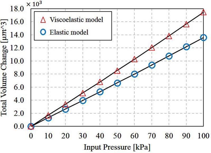
Drifts of color intensity were observed in the static evaluation shown in Fig. 7. The positive drift is possibly due to the viscoelastic property of the PDMS. The viscoelastic property is referred as time-dependent responses such as stress relaxation and strain creep.19 In other words, the chamber deformation may gradually increase under the same loading pressure, and it may result in the gradual increase of color intensity. Figure 9 shows the simulation results of the deformation in the sensing chamber with both viscoelastic and elastic modeling. The same Young's modulus and Poisson ratio are used for the viscoelastic modeling with additional shear modulus and bulk modulus .20 The results show that the deformation of the viscoelastic modeling is greater than the deformation in the elastic modeling in equilibrium states (). That means a greater deformation would occur by implementing viscoelastic characteristics, and it may lead to the positive drift. On the other hand, the negative drift may due to the unsealed inlet of the colored fluid. Fluid evaporation and cohesion may bring out the sensing fluid from the sensing chamber and result in the drop of color intensity.
FIG. 9.
Different deformation of sensing chamber in simulation with viscoelastic and elastic modeling for PDMS.
B. Transmission loss in dynamic responses
There is a critical difference between the evaluations on dynamic and static tests of the proposed sensor. The input pressure in dynamic evaluation would not necessary reach to an equilibrium during the test. In other words, we were blind from the actual input pressure reached at the proposed sensor, and the pressure signal may be changed during the transmission from the regulated source.
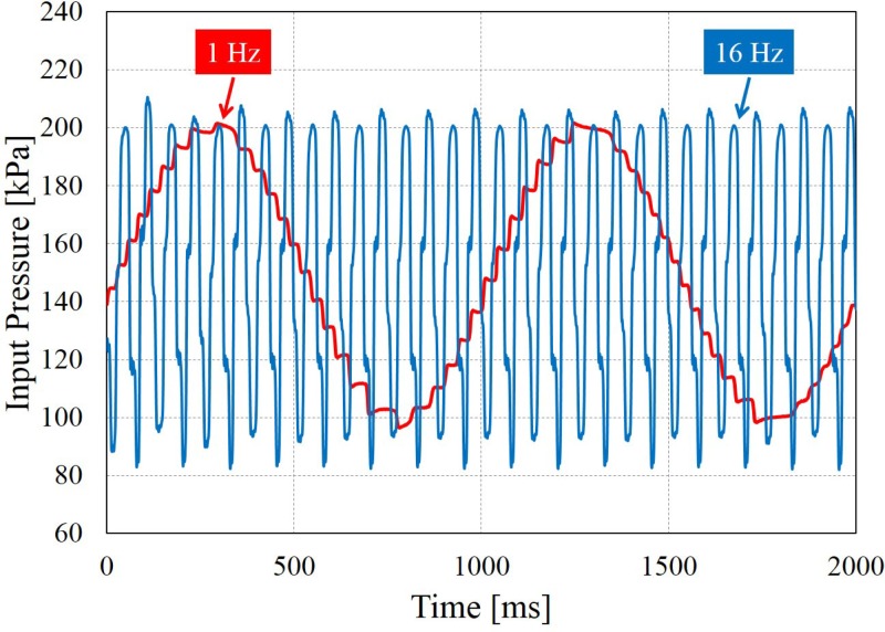
Figure 10 shows two actual measurements of the input pressures with the frequencies of 1 Hz and 16 Hz, and they were measured at the outlet of the reference sensor during the dynamic test. The amplitudes were apparently not suppressed from 1 Hz to 16 Hz. All the input pressures were checked having similar amplitudes. The input amplitude is even greater at high frequencies due to the overshoot of PID control. Therefore, the reducing amplitude showing in Figs. 8(b)–8(f) was not caused by the input pressure but by the combined effect of the sensor and the transmission. To the best of the authors' knowledge, since there are no commercial sensors available to be utilized as a reference inside a microfluidic chip, the completed dynamic characteristic of the proposed sensor remains unidentified. A technical note on dynamic responses based on current setup is in the supplementary material.24 Nevertheless, it is still fair to say, that the dynamic responses in Figs. 8(b)–8(f) were underestimated for the actual capability of the proposed sensor. It is because partial amplitude drop may be occurred during the transmission. As a result, it is also safe to say, that the proposed sensor can at least respond to 16 Hz of signal.
FIG. 10.
Two samples of the pressure input in dynamic test. The amplitude of the sinusoidal pressure signals is maintained under 1 Hz and 16 Hz.
C. Sensor implementation in other microfluidic designs
The implementation of the proposed sensor is straightforward. A user only needs to place the concentric chamber design next to the place to be measured, and connect the probe channel to the point of interest. The sensor can be easily applied to different microfluidic systems because of its single layer design. For example, the proposed sensor can be implemented in microfluidic culture environment for monitoring the pressure condition during the culture.21 No alignment between layers for chip fabrication is needed, and a high success rate of chip fabrication is expected. The additional cost for implementing the sensor is the sensing fluid which is less than 1 USD for the editable color, as the one used in this paper. To achieve a more precise monitoring on fluid flow, pricey microbeads can be used instead of colored fluid. However, the user should pay attention since the microbeads might adhere to the PDMS and result in significant signal drift as reported in our previous work.17 Another advantage of the proposed sensor is that the pressure can be monitored at the same time with other vision-based applications such as cell deformation in deformability tests.4,22,23
VI. CONCLUSION
An on-chip pressure sensor with single-layer concentric chamber design is proposed and evaluated. Four concluding remarks for this sensor are: (1) the sensor is easy-implement and low-cost because of its single-layer design. (2) The local pressure is determined by color intensity using the proposed sensor. No additional instruments or electricity are necessary. (3) The correlation of 0.974 between the static pressure and color intensity is obtained in static test. (4) The sensor successfully identified the sinusoidal pressure signals up to 16 Hz by a general 60 fps VGA camera in dynamic tests.
ACKNOWLEDGMENTS
This work was supported by Grant Nos. #23106003, #15 K13912, and #26820086 from The Ministry of Education, Culture, Sports, Science and Technology (MEXT) of Japan.
References
- 1. Zheng Y., Nguyen J., Wei Y., and Sun Y., “ Recent advances in microfluidic techniques for single-cell biophysical characterization,” Lab Chip 13(13), 2464–2483 (2013). 10.1039/c3lc50355k [DOI] [PubMed] [Google Scholar]
- 2. Gu W., Zhu X., Futai N., Cho B. S., and Takayama S., “ Computerized microfluidic cell culture using elastomeric channels and Braille displays,” Proc. Natl. Acad. Sci. U.S.A. 101(45), 15861–15866 (2004). 10.1073/pnas.0404353101 [DOI] [PMC free article] [PubMed] [Google Scholar]
- 3. Chen J., Zheng Y., Tan Q., Shojaei-Baghini E., Zhang Y. L., Li J., Prasad P., You L., Wu X. Y., and Sun Y., “ Classification of cell types using a microfluidic device for mechanical and electrical measurement on single cells,” Lab Chip 11(18), 3174–3181 (2011). 10.1039/c1lc20473d [DOI] [PubMed] [Google Scholar]
- 4. Tsai C. D., Sakuma S., Arai F., Taniguchi T., Ohtani T., Sakata Y., and Kaneko M., “ Geometrical alignment for improving cell evaluation in a microchannel with application on multiple myeloma red blood cells,” RSC Adv. 4(85), 45050–45058 (2014). 10.1039/C4RA08276A [DOI] [Google Scholar]
- 5. Tsai C. D., Sakuma S., Arai F., and Kaneko M., “ A new dimensionless index for evaluating cell stiffness-based deformability in microchannel,” IEEE Trans. Biomed. Eng. 61(4), 1187–1195 (2014). 10.1109/TBME.2013.2296624 [DOI] [PubMed] [Google Scholar]
- 6. Wu M. H., Huang S. B., and Lee G. B., “ Microfluidic cell culture systems for drug research,” Lab Chip 10, 939–956 (2010). 10.1039/b921695b [DOI] [PubMed] [Google Scholar]
- 7. Yue T., Nakajima M., Takeuchi M., Hu C., Huang Q., and Fukuda T., “ On-chip self-assembly of cell embedded microstructures to vascular-like microtubes,” Lab Chip 14(6), 1151–1161 (2014). 10.1039/c3lc51134k [DOI] [PubMed] [Google Scholar]
- 8. Monzawa T., Kaneko M., Tsai C. D., Sakuma S., and Arai F., “ On-chip actuation transmitter for enhancing the dynamic response of cell manipulation using a macro-scale pump,” Biomicrofluidics 9, 014114 (2015). 10.1063/1.4907757 [DOI] [PMC free article] [PubMed] [Google Scholar]
- 9. Wu C., Liao W., and Tung Y., “ Integrated ionic liquid-based electrofluidic circuits for pressure sensing within polydimethylsiloxane microfluidic systems,” Lab Chip 11(10), 1740–1746 (2011). 10.1039/c0lc00620c [DOI] [PubMed] [Google Scholar]
- 10. Dai C. L., Lu P. W., Chang C., and Liu C. Y., “ Capacitive micro pressure sensor integrated with a ring oscillator circuit on chip,” Sensors 9, 10158–10170 (2009). 10.3390/s91210158 [DOI] [PMC free article] [PubMed] [Google Scholar]
- 11. Liu M., Shih H., Wu J., Weng T., Wu C., Lu J., and Tung Y., “ Electrofluidic pressure sensor embedded microfluidic device: A study of endothelial cells under hydrostatic pressure and shear stress combinations,” Lab Chip 13(9), 1743–1753 (2013). 10.1039/c3lc41414k [DOI] [PubMed] [Google Scholar]
- 12. Barnkob R., Augustsson P., Laurell T., and Bruus H., “ Measuring the local pressure amplitude in microchannel acoustophoresis,” Lab Chip 10(5), 563–570 (2010). 10.1039/b920376a [DOI] [PubMed] [Google Scholar]
- 13. Srivastava N. and Burns M. A., “ Microfluidic pressure sensing using trapped air compression,” Lab Chip 7(5), 633–637 (2007). 10.1039/b617067f [DOI] [PMC free article] [PubMed] [Google Scholar]
- 14. Huang C., Gregory J. W., and Sullivan J. P., “ Microchannel pressure measurements using molecular sensors,” J. Microelectromech. Syst. 16(4), 777–785 (2007). 10.1109/JMEMS.2007.892914 [DOI] [Google Scholar]
- 15. Orth A., Schonbrun E., and Crozier K. B., “ Multiplexed pressure sensing with elastomer membranes,” Lab Chip 11(22), 3810 (2011). 10.1039/c1lc20114j [DOI] [PubMed] [Google Scholar]
- 16. Kim S. K. and Daniel I. M., “ Pressure measurement technique in nano- and micro-channels using atomic force microscopy,” Inverse Prob. Sci. Eng. 14(7), 701–709 (2006). 10.1080/17415970600557273 [DOI] [Google Scholar]
- 17. Tsai C. D., Nakamura T., and Kaneko M., “ An on-chip, electricity-free and single-layer pressure sensor for microfluidic applications,” in International Conference on Intelligent Robots and Systems, IROS (2015), pp. 165–170. [Google Scholar]
- 18. Tsai C. D. and Kaneko M., “ On-chip micro manometer,” in Proceedings of the 19th International Conference on Miniaturized Systems for Chemistry and Life Sciences, μTAS15, Gyeongju, South Korea, October (2015), pp. 1879–1881. [Google Scholar]
- 19. Tsai C. D., Kao I., Higashimori M., and Kaneko M., “ Modeling, sensing and interpretation of viscoelastic contact interface,” J. Adv. Rob. 26, 1393–1418 (2012). 10.1080/01691864.2012.689744 [DOI] [Google Scholar]
- 20. Karasudhi P., Foundations of Solid Mechanics ( Springer, Netherlands, 1991), vol. 3. [Google Scholar]
- 21. Fu C.-Y., Tseng S.-Y., Yang S.-M., Hsu L., Liu C.-H., and Chang H.-Y., “ A microfluidic chip with a U-shaped microstructure array for multicellular spheroid formation, culturing and analysis,” Biofabrication 6, 015009 (2014). 10.1088/1758-5082/6/1/015009 [DOI] [PubMed] [Google Scholar]
- 22. Zheng Y., Shojaei-Baghini E., Azad A., Wang C., and Sun Y., “ High-throughput biophysical measurement of human red blood cells,” Lab Chip 12, 2560–2567 (2012). 10.1039/c2lc21210b [DOI] [PubMed] [Google Scholar]
- 23. Gossett D. R., Tse H. T. K., Lee S. A., Ying Y., Lindgren A. G., Yang O. O., Rao J., Clark A. T., and Di Carlo D., “ Hydrodynamic stretching of single cells for large population mechanical phenotyping,” Proc. Natl. Acad. Sci. U.S.A. 109, 7630–7635 (2012). 10.1073/pnas.1200107109 [DOI] [PMC free article] [PubMed] [Google Scholar]
- 24.See supplementary material at http://dx.doi.org/10.1063/1.4945412E-BIOMGB-10-028602 for the videos of the sensor in action, experimental estimations of PDMS deformation and the dynamic characteristics of the sensor.
- 25.The offset syringe is connected to the fluid system through a three way valve and is in parallel to the main flow. The pressure offset is adjusted only at beginning of test.
- 26.The values of the color intensity are calculated by build-in function rgb2gray() in Matlab with an inversion, and the exact function is , where I, R, G, and B are the color intensity and the values of red, green, and blue, respectively.
- 27.The automatic camera adjustments, such as shutter speed and white balance, were all turned off during the recording to avoid changes of color intensity other than chamber deformation. The ambient lighting condition was kept as similar as possible.
- 28. Sessoms D. A., Belloul M., Engl W., Roche M., Courbin L., and Panizza P., “ Droplet motion in microfluidic networks: Hydrodynamic interactions and pressure-drop measurements,” Phys. Rev. E 80(1), 016317 (2009). 10.1103/PhysRevE.80.016317 [DOI] [PubMed] [Google Scholar]
- 29. Hosokawa K., Hanada K., and Maeda R., “ A polydimethylsiloxane (pdms) deformable diffraction grating for monitoring of local pressure in microfluidic devices,” J. Micromech. Microeng. 12(1), 1–6 (2002). 10.1088/0960-1317/12/1/301 [DOI] [Google Scholar]
Associated Data
This section collects any data citations, data availability statements, or supplementary materials included in this article.
Data Citations
- See supplementary material at http://dx.doi.org/10.1063/1.4945412E-BIOMGB-10-028602 for the videos of the sensor in action, experimental estimations of PDMS deformation and the dynamic characteristics of the sensor.


