Abstract
We present a nanosecond Q-switched Erbium-doped fiber (EDF) laser system operating at 1600 nm with a tunable repetition rate from 100 kHz to 1 MHz. A compact fiber coupled, acousto-optic modulator-based EDF ring cavity was used to generate a nanosecond seed laser at 1600 nm, and a double-cladding EDF based power amplifier was applied to achieve the maximum average power of 250 mW. In addition, 12 ns laser pulses with the maximum pulse energy of 2.4 μJ were obtained at 100 kHz. Furthermore, the Stokes shift by Raman scattering over a 25 km long fiber was measured, indicating that the laser can be potentially used to generate the high repetition rate pulses at the 1.7 μm region. Finally, we detected the photoacoustic signal from a human hair at 200 kHz repetition rate with a pulse energy of 1.2 μJ, which demonstrates that a Q-switched Er-doped fiber laser can be a promising light source for the high speed functional photoacoustic imaging.
Near-infrared (NIR) light from 700 to 2500 nm has been regarded as a promising approach to further increase the depth in optical imaging, such as in near-infrared imaging,1,2 optical coherence tomography (OCT),3,4 multiphoton microscopy (MPM),5 and photoacoustic imaging (PAI).6–8 PAI, which is based on detection of the acoustic wave generated by absorption of nanosecond-laser pulses, can provide the structural and functional information of biological tissue.6,8 NIR lasers have been demonstrated to improve the imaging depth of PAI with higher resolution due to their lower absorption and weaker light scattering compared to the laser operating in the visible wavelength region.6,9 The imaging speed of PAI depends highly on the laser pulse repetition rate (PRR), especially in optical-resolution photoacoustic microscopy (OR-PAM).10,11 Traditionally, a dye laser or an optical parametric oscillator (OPO) is used to generate the laser at the specified wavelength in the NIR region.9,12 However, the PRR of these lasers is usually in the 10 Hz to kHz level, which is too slow for real-time imaging. On the other hand, intensity modulated laser diodes (LDs) with several kHz PRR have been demonstrated as an alternative source for PAI. However, LDs usually have low pulse energies with broad pulse width which leads to low axial resolution.13–15
Due to its high optical absorption by lipids, a laser in the 1.7 μm range has attracted great interest in intravascular photoacoustic (IVPA) imaging for the detection of vulnerable atherosclerotic plaques which typically have a large, lipid-rich, necrotic core.12,16 In our recent work, we have developed a high-speed OPO laser at 1.7 μm with 500 Hz PRR to increase the imaging speed by almost two orders of magnitude faster than that previously reported.12 However, assuming 500 A-lines for each cross-sectional image, a laser with 500 Hz PRR only allows an imaging speed of one frame per second. Therefore, a faster laser with 10 kHz or higher PRR is needed to achieve real-time IVPA imaging.
Q-switched rare-earth-doped fiber lasers, using rare-earth elements such as Ytterbium (Yb), Erbium (Er), or Thulium (Tm) as a gain medium, have attracted great interest in past decades.17–20 Passive and active Q-switching techniques are widely used to modulate the Q-factors in a laser cavity to generate high-energy pulses with nanosecond temporal duration. Compared to passive methods, active Q-switching has the advantage of flexible control of the repetition rate by external modulation which can achieve PRRs from the kHz to MHz range.18,21 Previously, several works demonstrated the use of Q-switched Yb-doped fiber laser (YDFL, 1064 nm/532 nm) in PAI.10,22 However, Q-switched Er-doped fiber laser (EDFL), specifically in a wavelength range of around 1500–1600 nm has the potential of wavelength shifting to the 1.7 μm region by stimulated Raman scattering23 and to the 800 nm region by second harmonic generation,24 which has not been applied in PAI yet.
In this work, we present a nanosecond Q-switched EDFL working at 1600 nm center wavelength with tunable PRR from 100 kHz to 1 MHz. At 100 kHz, the maximum pulse energy of ∼2.4 μJ was measured. The laser was tested to generate the photoacoustic signal from a human hair, demonstrating the potential application of the laser in PAI. Furthermore, the wavelength of the laser was shifted by Stokes Raman scattering in a 25 km long single mode fiber which shows the potential application of the laser for generating the output in the 1.7 μm wavelength region.
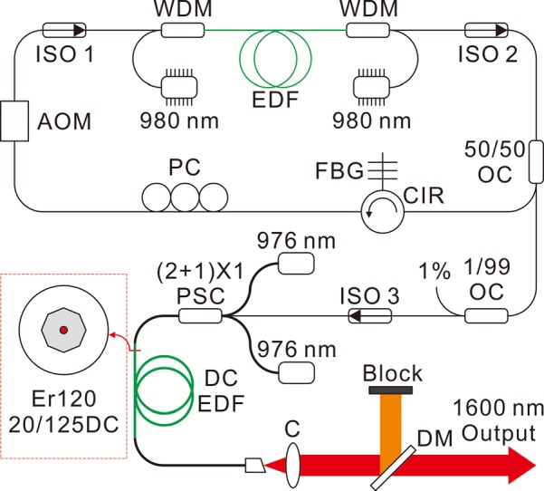
The schematic diagram of the fiber laser is shown in Fig. 1. The laser consists of a Q-switched EDFL seed at 1600 nm and a power amplifier. In the ring laser cavity of the Q-switched EDFL seed, a 34-m long L-band EDF fiber with a peak absorption of 20 dB/m at 1530 nm (Fibercore, M12-980-125) was bi-directionally pumped by two pump laser modules at 980 nm (JDSU, S30). The pump modules use fiber Bragg grating (FBG) stabilizations to lock the emission wavelength and provide a noise free, narrowband spectrum laser output through a HI-1060 fiber. Two 980/1600 nm wavelength-division multiplexers (WDMs) were used to combine the pump laser and operating laser and then transmit the light to the EDF fiber. The total pump power launched was 400 mW in this experiment.
FIG. 1.

Schematic of the Q-switched EDFL system. Inserted: cross-section of double-cladding EDF fiber; EDF: Erbium-doped fiber, WDM: wavelength-division multiplexer; AOM: acousto-optic modulator; FBG: fiber-Bragg grating; ISO: isolator; PC: polarization controller; CIR: circulator; OC: optical coupler; DCEDF: double-cladding Erbium-doped fiber; PSC: pump-signal combiner; C: collimator; DM: dichroic mirror.
A compact fiber coupled acousto-optic modulator (AOM, Gooch & Housego, Fibre-Q) with a 200 MHz frequency shift was optimized for working at 1600 nm wavelength, with a 50-dB extinction ratio at 1st order on/off switching and 10 ns rise-time/fall-time. The on/off status of the AOM was modulated by an external square waveform generated from an 80 MHz function/arbitrary waveform generator. Two optical isolators were used to ensure the unidirectional propagation of the light and allow a stable single-frequency operation simultaneously. A custom manufactured FBG was inserted in the laser cavity through a fiber circulator. The FBG has 99% reflectivity at a center wavelength of 1600 nm with 1 nm bandwidth. A polarization controller (PC) was placed in the cavity to optimize the polarization state of the light propagating in the fiber ring. A 50/50 fiber coupler was used as the output coupler and a 1/99 optical coupler was used for monitoring the pulse power through the 1% port.
The power amplifier was composed of a 4.5-m long double-cladding Erbium-doped fiber (DCEDF, Liekki Er120-20/125DC, NA: 0.09/0.46) with 20-μm core diameter and 125-μm octagonal cladding as shown in the inserted figure in Fig. 1. Two high power 10 W fiber coupled diode lasers (JDSU, 10 W 9368 L4 series) at 976 nm were used to pump the power amplifier. The diode lasers were coupled to 105/125 multimode fiber (MMF) with 0.22 NA. A (2 + 1) × 1 pump combiner with two pump ports (105/125 MMF, 0.22 NA), one signal port (single mode fiber, 0.14 NA) and one output port with a passive double-cladding fiber which has the same octagonal cladding as DCEDF was used to combine the pump laser and pulsed signal to the DCEDF. In order to couple the power with high efficiency, the DCEDF was fusion spliced to the passive DCF using a filament fusion splicer (Vytran, GPX-3000) by carefully adjusting the angle to reduce the loss. The output end of DCEDF was fusion spliced to a portion of passive double-cladding fiber with an 8° cleaved facet to prevent the internal reflection. Finally, the laser was collimated by a lens and filtered by a dichroic mirror. The transmitted pump laser at 976 nm was blocked while the 1600 nm output was delivered to the PAI system.
First, we tested the Q-switched EDFL at 100 kHz PRR. When the seed laser was pumped with a total power of 0.4 W, the average output power was measured as 0.05 W. The seed laser was then amplified by the DCEDF amplifier. In total, a 14 dB gain was achieved under 5 W pump power. By using a longer active fiber, a higher flat gain could be achieved. However, this will in turn lead to significant nonlinearities.
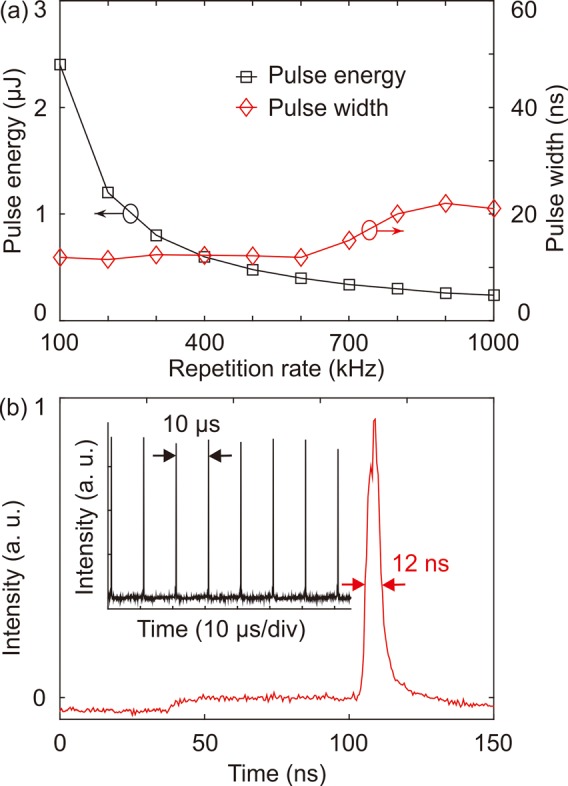
When the pump power was further increased, the amplified spontaneous emission (ASE) at 1530 nm could be observed due to the maximum gain of EDF which typically occurs in the wavelength region around 1530–1560 nm. We fixed the total pump power at 5.4 W and increased the PRR from 100 kHz to 1 MHz. As shown in Fig. 2(a), the pulse energy (black square) is inversely proportional to the PRR. The maximum pulse energy obtained at 100 kHz was measured to be ∼2.4 μJ. And at 1 MHz, the pulse energy was measured to be ∼0.24 μJ.
FIG. 2.

(a) The measured pulse energy (black square) and pulse width (red diamond) of the output pulse as function of the PRR. (b) The temporal trace of the output pulse at 100 kHz: the inserted figure is the pulse train.
We also measured the temporal pulse trace using a 14.5 GHz biased extended InGaAs photodetector (Newport, 818-BB-51) and a 2.5-GS/s digital oscilloscope. Fig. 2(b) is the measured pulse trace and the pulse train at 100 kHz under the maximum pump power and shows the pulse width and pulse spacing as 12 ns and 10 μs, respectively. From Fig. 2(a), we can see the pulse width (red diamond) increasing with the PRR, from 12 ns to 23 ns. The output end of the fiber was spliced to an 8° angled end cap to reduce the Fresnel reflection from the fiber-air interface and avoided the generation of multiple pulses within the amplifier.
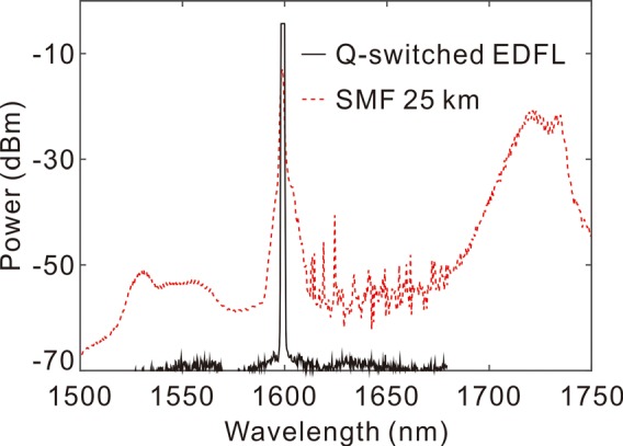
The optical spectrum of the output laser was measured by an optical spectrum analyzer (Ando, AQ-6315). Fig. 3 shows the measured output spectrum at 100 kHz with a black solid line under the maximum pump power. The center wavelength was located at ∼1600 nm with a spectral width of ∼2 nm. There was no significant nonlinear effect during the high power amplification. However, when the pump power was increased, broad ASE around 1550 nm was observed. The spectrum is plotted on a log scale to emphasize the contrast between the laser and the ASE. Furthermore, to demonstrate the potential Stokes shift of the wavelength to the 1.7 μm region, the laser was coupled into a 25 km single mode fiber (SM28). Despite the loss in the long SM fiber, the output at the 1.7 μm region could be observed which matches the Raman Stokes shift of 13 THz in a silica based fiber.
FIG. 3.

Measured optical spectrum of the laser (black solid line) and wavelength shift over 25 km SM fiber (red dotted line).
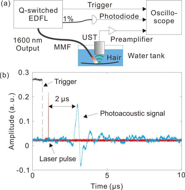
Finally, we demonstrated the Q-switched EDFL in PAI application by inducing the photoacoustic signal from a human hair. The corresponding experiment setup is shown in Fig. 4(a). The laser was set at 200 kHz with 1.2 μJ pulse energy and guided by a 200-μm core multimode fiber. The pulse energy at the fiber tip was measured to be ∼0.9 μJ. A human hair was used as the target with a diameter of ∼80 μm. The excited photoacoustic signal was detected by a 10-MHz ultrasound transducer and then amplified by a 20 dB preamplifier. The temporal profiles of the PA signal (blue solid line), as well as the Q-switching trigger (black dashed line) and the laser pulses (red solid line) recorded from the 1% seed laser, were captured by a digital oscilloscope.
FIG. 4.

(a) Experiment setup for photoacoustic signal detection from a human hair. (b) Recorded temporal profiles of trigger (black dashed line), laser pulses (red solid line), and PA signal (blue solid line).
As shown in Fig. 4(b), the PA signal appears at ∼2 μs after the laser pulse and indicates the propagation distance of ∼3 mm from the hair to the transducer. As the fiber tip was located closely above the hair, the diameter of the laser spot (200 μm) was much larger than the diameter of the hair, and the laser fluence on the hair was estimated to be approximately 0.7 mJ/cm2. Despite the low laser fluence on the target, the PA signal generated by the hair was clearly detectable without signal averaging. In OR-PAM, a lower laser energy level as few as tens of nanojoules is generally needed due to the two orders of magnitude higher efficiency of focused excitation vs. unfocused excitation.11,15 Therefore, even if the laser PRR is increased up to 1 MHz, the laser energy would still be enough for OR-PAM.
In conclusion, we built a nanosecond Q-switched EDFL source at 1600 nm with a tunable PRR from 100 kHz to 1 MHz and the pulse width from 12 ns to 23 ns, respectively. The maximum pulse energy was measured to be ∼2.4 μJ at 100 kHz. Furthermore, by using Raman scattering in silica based fiber, the laser wavelength could be shifted to generate high PRR pulses at the 1.7 μm. The preliminary proof-of-principle experiment shows that the Q-switched EDFL can be used as a potential excitation source for fast functional OR-PAM in a biomedical application.
Acknowledgments
This work was supported by the Basic Science Research Program through the National Research Foundation of Korea (NRF) grant funded by the Korea Government (MSIP) (NRF-2015R1A2A1A15056030), National Institutes of Health (R01HL-125084, R01HL-127271, R01EY-021529, and P41EB-015890), and AFOSR FA9550-14-1-0034. Professor Chen has a financial interest in OCT Medical, Inc., which, however, did not support this work.
References
- 1. Smith A. M., Mancini M. C., and Nie S. M., Nat. Nanotechnol. 4(11), 710 (2009). 10.1038/nnano.2009.326 [DOI] [PMC free article] [PubMed] [Google Scholar]
- 2. Welsher K., Liu Z., Sherlock S. P., Robinson J. T., Chen Z., Daranciang D., and Dai H., Nat. Nanotechnol. 4(11), 773 (2009). 10.1038/nnano.2009.294 [DOI] [PMC free article] [PubMed] [Google Scholar]
- 3. Sharma U., Chang E. W., and Yun S. H., Opt. Express 16(24), 19712 (2008). 10.1364/OE.16.019712 [DOI] [PMC free article] [PubMed] [Google Scholar]
- 4. Jung E. J., Lee J. H., Rho B. S., Kim M. J., Hwang S. H., Lee W. J., Song J. J., Jeong M. Y., and Kim C. S., IEEE J. Sel. Top. Quantum Electron. 18(3), 1200 (2012). 10.1109/JSTQE.2011.2167962 [DOI] [Google Scholar]
- 5. Horton N. G., Wang K., Kobat D., Clark C. G., Wise F. W., Schaffer C. B., and Xu C., Nat. Photonics 7(3), 205 (2013). 10.1038/nphoton.2012.336 [DOI] [PMC free article] [PubMed] [Google Scholar]
- 6. Hai P. F., Yao J. J., Maslov K. I., Zhou Y., and Wang L. H. V., Opt. Lett. 39(17), 5192 (2014). 10.1364/OL.39.005192 [DOI] [PMC free article] [PubMed] [Google Scholar]
- 7. Buma T., Wilkinson B. C., and Sheehan T. C., Biomed. Opt. Express 6(8), 2819 (2015). 10.1364/BOE.6.002819 [DOI] [PMC free article] [PubMed] [Google Scholar]
- 8. Wang L. V. and Hu S., Science 335(6075), 1458 (2012). 10.1126/science.1216210 [DOI] [PMC free article] [PubMed] [Google Scholar]
- 9. Wang X. D., Ku G., Wegiel M. A., Bornhop D. J., Stoica G., and Wang L. H. V., Opt. Lett. 29(7), 730 (2004). 10.1364/OL.29.000730 [DOI] [PubMed] [Google Scholar]
- 10. Shi W., Hajireza P., Shao P., Forbrich A., and Zemp R. J., Opt. Express 19(18), 17143 (2011). 10.1364/OE.19.017143 [DOI] [PubMed] [Google Scholar]
- 11. Yao J., Wang L., Yang J. M., Maslov K. I., Wong T. T., Li L., Huang C. H., Zou J., and Wang L. V., Nat. Methods 12(5), 407 (2015). 10.1038/nmeth.3336 [DOI] [PMC free article] [PubMed] [Google Scholar]
- 12. Piao Z. L., Ma T., Li J. W., Wiedmann M. T., Huang S. H., Yu M. Y., Shung K. K., Zhou Q. F., Kim C. S., and Chen Z. P., Appl. Phys. Lett. 107(8), 083701 (2015). 10.1063/1.4929584 [DOI] [PMC free article] [PubMed] [Google Scholar]
- 13. Allen T. J. and Beard P. C., Opt. Lett. 31(23), 3462 (2006). 10.1364/OL.31.003462 [DOI] [PubMed] [Google Scholar]
- 14. Zeng L. M., Liu G. D., Yang D. W., and Ji X. R., Appl. Phys. Lett. 102(5), 053704 (2013). 10.1063/1.4791566 [DOI] [Google Scholar]
- 15. Zeng L., Piao Z., Huang S., Jia W., and Chen Z., Opt. Express 23(24), 31026 (2015). 10.1364/OE.23.031026 [DOI] [PMC free article] [PubMed] [Google Scholar]
- 16. Wang B., Karpiouk A., Yeager D., Amirian J., Litovsky S., Smalling R., and Emelianov S., Opt. Lett. 37(7), 1244 (2012). 10.1364/OL.37.001244 [DOI] [PubMed] [Google Scholar]
- 17. Alvarez-Chavez J. A., Offerhaus H. L., Nilsson J., Turner P. W., Clarkson W. A., and Richardson D. J., Opt. Lett. 25(1), 37 (2000). 10.1364/OL.25.000037 [DOI] [PubMed] [Google Scholar]
- 18. Chang Y. M., Lee J., Jhon Y. M., and Lee J. H., Opt. Express 19(27), 26911 (2011). 10.1364/OE.19.026911 [DOI] [PubMed] [Google Scholar]
- 19. Barmenkov Y. O., Kir'yanov A. V., Cruz J. L., and Andres M. V., Appl. Phys. Lett. 104(9), 091124 (2014). 10.1063/1.4867888 [DOI] [Google Scholar]
- 20. Pearson L., Kim J. W., Zhang Z., Ibsen M., Sahu J. K., and Clarkson W. A., Opt. Express 18(2), 1607 (2010). 10.1364/OE.18.001607 [DOI] [PubMed] [Google Scholar]
- 21. Sun Z., Hasan T., Torrisi F., Popa D., Privitera G., Wang F., Bonaccorso F., Basko D. M., and Ferrari A. C., ACS Nano 4(2), 803 (2010). 10.1021/nn901703e [DOI] [PubMed] [Google Scholar]
- 22. Wang Y., Maslov K., Zhang Y., Hu S., Yang L., Xia Y., Liu J., and Wang L. V., J. Biomed. Opt. 16(1), 011014 (2011). 10.1117/1.3525643 [DOI] [PMC free article] [PubMed] [Google Scholar]
- 23. Ji J. H., Codemard C. A., Ibsen M., Sahu J. K., and Nilsson J., IEEE J. Sel. Top. Quantum Electron. 15(1), 129 (2009). 10.1109/JSTQE.2008.2010229 [DOI] [Google Scholar]
- 24. Son S. N., Song J. J., Kang J. U., and Kim C. S., Sensors 11(6), 6125 (2011). 10.3390/s110606125 [DOI] [PMC free article] [PubMed] [Google Scholar]


