

Abstract
The purpose of this study was to develop and validate a new chin template system for a two-piece narrowing genioplasty. Nine patients with wide chin deformities were enrolled. Surgeries were planned with the computer-aided surgical simulation (CASS) planning method. Surgical splints and chin templates were designed in a computer and fabricated using a three-dimensional printing technique. The chin template system included a cutting guide and a repositioning guide for a two-piece narrowing genioplasty. These guides were also designed to avoid the mental foramen area and inferior alveolar nerve loops during the osteotomy, for nerve protection. After surgery, the outcome evaluation was completed by first superimposing the postoperative computed tomography model onto the planned model, and then measuring the differences between the planned and actual outcomes. All surgeries were completed successfully using the chin template system. No inferior alveolar nerve damage was seen in this study. With the use of the chin templates, the largest linear root mean square deviation (RMSD) between the planned and the postoperative chin segments was 0.7 mm and the largest angular RMSD was 4.5°. The results showed that the chin template system provides a reliable method of transfer for two-piece osseous narrowing genioplasty planning.
Keywords: computer-aided surgical simulation, computer-aided design/computer-aided manufacturing, surgical template, genioplasty
Introduction
Osseous genioplasty procedures are used widely to correct chin deformities1–4. These procedures are challenging because the chin deformity may exist in all three dimensions; thus it is critical not only to make a correct diagnosis and surgical plan for the genioplasty, but also to transfer the plan precisely to the patient at the time of surgery. The location of the osteotomy and the movement of the bony segment will directly impact the surgical outcome5. In a monoblock genioplasty, the bony segment may be controlled simply using a holding screw and repositioned based on intraoperative measurements6. However, in a segmentalized genioplasty (e.g., narrowing genioplasty), it is rather more difficult to precisely perform an osteotomy and reposition the two chin piece segments correctly following the surgical plan.
With the rapid developments made in computer-aided surgical simulation (CASS) technology, computer-aided design/computer-aided manufacturing (CAD/CAM) surgical templates are now used by surgeons as a guide to assist them in performing an accurate osteotomy and in moving the bony segment to the desired position, exactly as planned in the computer7–9. There are a few reports in the literature on the use of genioplasty templates and these have indicated good surgical outcomes9. However, the design of these templates is bulky, they are difficult to use intraoperatively, and they can only be applied to a monoblock genioplasty. Therefore, the purpose of this study was to develop and validate a new chin template system for a two-piece osseous narrowing genioplasty. This template system includes two surgical guides: a cutting guide that defines the osteotomy cutting line and the screw holes prior to the osteotomy, and a repositioning guide that precisely repositions the two chin piece segments into the planned position and orientation using the predefined screw holes.
Materials and methods
Nine Chinese female patients (median age 22 years, range 18–27 years) with wide chin deformities were enrolled in this study between April and November 2014. Asian women often complain of a prominent masculine chin and square contour of their face. A narrowing genioplasty is a desirable procedure to produce a more feminine facial contour with a slenderer lower third of the face10. Therefore, the indication for a two-piece narrowing genioplasty was determined based on the patient's complaint and the doctor's clinical aesthetic assessment.
Inclusion criteria for the study encompassed (1) patients who were scheduled to undergo a two-piece narrowing genioplasty as a part of their treatment, (2) patients who were scheduled to undergo a computed tomography (CT) scan as a part of their diagnosis and treatment, and (3) patients who agreed to participate in the study. Patients with a craniofacial syndrome, those who had undergone a previous osseous genioplasty, those with a previous mandibular trauma, and patients requiring only a monoblock genioplasty were excluded. The study was approved by the ethics committee of the hospital prior to initiation. Informed consent was obtained from each patient before enrollment. The main reason for enrolling only female patients is that it is principally Asian women who complain about a prominent masculine chin and square contour of the face and who therefore desire a narrowing genioplasty to produce a more feminine facial contour10 [Au?1].
Surgical planning following the CASS protocol11
A CT scan of the patient's head was acquired preoperatively (GE Healthcare, Fairfield, CT, USA). A wax bite was used to slightly separate the maxilla and mandible. The axial slice was taken at a thickness of 1.25 mm with the patient in a supine position. The CT data were imported into planning software (ProPlan 1.4; Materialise NV, Leuven, Belgium) to generate three-dimensional (3D) maxillary and mandibular models. The digital dental models were generated by scanning a set of stone dental models using a high-resolution laser surface scanner (Smartoptics AS, Bochum, Germany). The digital dental models were then imported and merged into the 3D skull model to replace the less-than-accurate CT teeth. This resulted in a computerized composite skull model with accurate rendition of both the bony structures and the teeth.
The composite skull model was then positioned in a unique reference frame8,11–14. In this study, nasion was defined as the origin of the reference frame for the composite skull model, with the x-axis running in the mediolateral direction, the y-axis in the anteroposterior direction, and the z-axis in the inferosuperior direction. The axial (XOY) plane was a plane parallel to the Frankfort horizontal (defined by the averaged right and left porion and orbitale), dividing the head into upper and lower parts. The midsagittal (YOZ) plane was a vertical plane dividing the head into right and left halves. Finally, the coronal (XOZ) plane was a vertical plane perpendicular to the other two planes.
After the reference frame of the composite skull model was established, a maxillary Le Fort I osteotomy, bilateral mandibular ramus sagittal split osteotomies (BSSRO), and a narrowing genioplasty were simulated in the computer based on clinical examination, cephalometric analysis, and 3D measurements, following the standard planning routine8,11,15–17. In addition, during the planning of the two-piece narrowing genioplasty, the inferior nerve canal positions were marked on the mandibular model in order to protect the inferior alveolar nerves (Fig. 1). Once the surgical plan was finalized, the surgical splints and genioplasty templates were designed in the computer using 3-matic software (Materialise NV, Leuven, Belgium) and fabricated using a 3D printing machine (3D Systems, Rock Hill, SC, USA). The surgical splint was designed following the same routine8,11,15–17. This splint was used to position the maxillary Le Fort I and mandibular distal segments intraoperatively. The template for the two-piece narrowing genioplasty was also designed in the computer with this new method. These were used intraoperatively for the two-piece narrowing genioplasty. Details are given below.
Fig. 1.

(A) The upper portion of the cutting guide is designed like a dental splint. The lower portion of the guide is designed to indicate the cutting lines and the trajectory of the cutting plane (indicated by the thickness of the cutting guide). (B) Six screw-hole drilling guides (black dots) are designed on both sides of the osteotomy cutting lines to provide stable bony reference landmarks. The inferior alveolar nerve (red arrow) is marked on the 3D model. (Chin segments are marked in orange; bony collisions for ostectomy during the repositioning are marked in blue; SH: screw hole.)
Two-piece narrowing genioplasty template system
To design the two-piece narrowing genioplasty templates, the 3D models of the distal mandible and the chin segment in both their initial position and final position are used. This new genioplasty template system includes two surgical guides: a cutting guide and a repositioning guide. The cutting guide is used to assist the surgeon in performing the osteotomy and for pre-drilling the screw holes (Fig. 1). During the design of the cutting guide, all 3D models of the bony segments are located in their original positions. The upper portion of the cutting guide is designed like a dental splint, serving as a locking mechanism to firmly attach the whole cutting guide onto the mandibular teeth8,11. The lower portion of the guide is designed to indicate the cutting lines for the two-piece genioplasty and the trajectory of the cutting plane (indicated by the thickness of the cutting guide). It is important to note that the cutting guide should not be extended to the mental foramen area. In addition, six screw-hole drilling guides, two on the distal mandible and two on each chin segment, are designed on both sides of the osteotomy cutting lines (Fig. 1). These screw holes on each bony segment serve as bony reference landmarks for automatic repositioning of the chin segments in the next step. Finally, a solid vertical bar is designed to rigidly connect the upper and lower portions of the cutting guide.
The repositioning guide is used to automatically reposition the two chin segments into their final positions (Fig. 2). During the design process, both the original and the planned positions of the two chin segments are used. The upper portion of the repositioning guide is designed to firmly attach the whole guide to the distal mandible using the two screw holes created previously by the cutting guide. The lower portion of the repositioning guide includes four repositioning screw holes, two for each chin segment, in their final planned positions. In order to achieve this, the chin segments are first positioned in their original locations. The screw holes created by the cutting guide are linked digitally to their corresponding chin segments. Each chin segment is then moved into its planned final position, bringing the screw holes along with it as an integrated unit. At the time of the surgery, the new location of the screw holes on the repositioning guide will automatically bring the chin segment into its final planned position as the screws are placed into the appropriate screw holes and tightened (Fig. 2).
Fig. 2.

(A) The bony collisions for ostectomy (marked in blue) and the screw holes (black dots) on each bony segment are marked using the cutting guide. (B) After the bony collisions are removed, the repositioning guide is installed. The upper portion of the guide is attached to the distal mandible using the original two screw holes (SH-1 and SH-2 [Au?3]). The lower portion of the guide includes four repositioning screw holes in their planned final positions. (C) The new location of the screw holes on the repositioning guide will automatically bring the chin segment into its planned final position as the screws are placed into the appropriate screw holes. (Chin segments are marked in orange; SH: screw hole.)
Surgery
All surgeries were performed by a single attending surgeon who is experienced in orthognathic surgery. During surgery, the CAD/CAM occlusal surgical splints were used to place the maxilla and mandible into the final planned positions as routine7,8,11,13.
All patients underwent a two-piece narrowing genioplasty using the new template system. The anterior surface of the chin was exposed as for a routine genioplasty procedure via intraoral approach. The first guide, the cutting guide, was positioned on the mandibular dentition exactly as planned in the computer. The lower portion of the guide was then attached firmly to the chin with six screws using the drilling holes designed on the cutting guide (Fig. 3A). Once the two-piece genioplasty osteotomy cutting lines were marked with a surgical saw as planned, the cutting guide and the screws were removed and the osteotomy continued (Fig. 3B).
Fig. 3.

(A) During the operation, the cutting guide was positioned on the mandibular dentition exactly as planned. The lower portion of the guide was attached firmly to the chin by six screws using the drilling holes. The resection margins guided the saw blade to perform the osteotomy as planned. (B) The cutting guide and the screws were removed to complete the osteotomy after the cutting lines had been marked and the screw holes had been drilled. (SH: screw hole.)
After the osteotomy was completed, the second guide, the repositioning guide, was installed firmly onto the distal mandible by aligning the two screw holes on the guide to the two corresponding screw holes on the distal mandible (Fig. 4A). Afterwards, each of the osteotomized chin segments was moved and rotated until the two corresponding screw holes on the chin segment and the guide were aligned. As the screws were placed and tightened, the chin segment was automatically moved into its final planned position and secured temporarily. Each chin segment was then stabilized by rigid fixation (Fig. 4B), following which the guide and associated screws were removed (Fig. 4C) and the surgical wound closed as usual.
Fig. 4.

(A) The repositioning guide was installed on the distal mandible by alignment with the previously drilled screw holes on the distal mandible. When the two corresponding screw holes on the chin segment and the guide were aligned, the chin segment was automatically moved to its final planned position and secured temporarily. (B) Each chin segment was then stabilized by rigid fixation. (C) Finally, the guide and associated screws were removed. (SH: screw hole.)
Outcome evaluation
A CT scan was acquired 3 days postoperatively. The postoperative CT scans represented the actual surgical outcomes. The outcome evaluation was started once all postoperative CT scans had been obtained. The accuracy of this new two-piece narrowing genioplasty template system was assessed by comparing the actual postoperative outcomes to the planned outcomes.
The postoperative 3D maxillary and mandibular models were generated using the same planning software (ProPlan). The postoperative 3D models were then imported into the same design software (3-matic). The outcome evaluation was completed by first digitizing a group of anatomical landmarks on the planned and the postoperative models. The differences in position and orientation between these landmarks were calculated. Details of the evaluation procedure are described below.
The premise was adopted that three points are sufficient to define the position and orientation of an object in 3D space14. Three corner points were digitized on each chin segment while in its planned final position (Fig. 5). The landmarks utilized were (1) the superomedial corner point on the buccal surface of the chin segment (point 1); (2) the inferomedial corner point (point 2), similar to menton; and (3) the posterolateral corner point on the buccal surface (point 3).
Fig. 5.
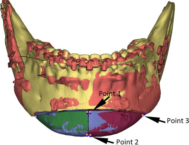
Three corner points were digitized on each chin segment while it was in the planned final position. Using the surface-best-fit method, each chin segment and three landmarks were registered to the corresponding postoperative chin segment. The landmarks on the planned models were marked in red, and the landmarks on the postoperative models were marked in blue. Point 1 is the superomedial corner point on the buccal surface of the chin segment; point 2 is the inferomedial corner point, similar to menton; point 3 is the posterolateral corner point on the buccal surface.
A ‘reversed’ routine developed by Xia et al.14 and Hsu et al.8 was used to ensure the correspondence of landmarks between the planned and the postoperative chin segments. First, the three landmarks were ‘glued’ onto the planned chin segment. Second, using the surface-best-fit method, each chin segment was registered to the corresponding postoperative chin segment. The three landmarks were also brought along with the chin segment accordingly. Third, the three landmarks on the planned chin segment were duplicated. The duplicated landmarks became the landmarks for the postoperative chin segment. Finally, the planned chin segment together with its landmarks was moved back to the originally planned position. Then the postoperative chin segment was registered to the planned chin segment using the surface-best-fit method. The coordinates of all of the landmarks in the planned and postoperative positions were recorded.
The linear differences were calculated using the centroids of the planned and postoperative chin segments. The centroid coordinates (xc, xc, xc) of each chin segment were computed using the following equations:
where (x1, x2, x3), (y1, y2, y3), and (z1, z2, z3), are the coordinates of the three landmarks on each chin segment. The linear differences in x (mediolateral), y (anteroposterior), and z (superoinferior) directions between the planned and postoperative centroid positions were computed.
The angular differences were computed as the discrepancies in pitch, roll, and yaw between the x, y, and z axes of the reference frames for the planned and the postoperative chin segments8,12 (Fig. 6). The calculation of the angular differences was completed automatically using a custom MATLAB program (MathWorks, Natick, MA, USA).
Fig. 6.

The pitch, roll, and yaw of a chin segment were measured by comparing the orientation of the reference frame for the chin segment (colored arrows) to the reference frame for the composite skull model (black lines). The red arrow is the transverse (x) axis, the blue arrow is the anteroposterior (y) axis, and the green arrow is the vertical (z) axis. The x, y, and z axes of the reference frame for the planned chin are parallel to the X, Y, and Z axes in the reference frame for the composite skull model. The origin of the reference frame for the chin segment is point 2. The deviation is intentionally enlarged to clearly indicate the method of angular difference calculation used in this study. (A) The first step is to measure the yaw, which is the angle between the x-axis of the reference frame for the chin and the X-axis of the reference frame for the composite skull model as they project on the axial plane (XOY plane, submental vertex view). (B) After the yaw has been calculated, the algorithm rotates the reference frame of the chin around the origin, aligning its x-axis to the X-axis of the reference frame of the skull (removing the yaw, submental vertex view). (C) This image illustrates the frontal view of the chin segment at the same orientation as in image B. After the yaw has been removed, the next step is to measure the roll, which is the angle between the z-axis of the chin and the Z-axis of the skull as they project on the coronal plane (Z–X plane [Au?4], frontal view). (D) The algorithm then rotates the reference frame around the origin to align the z-axis of the reference frame of the chin to the Z-axis of the reference frame of the skull (removing the roll, frontal view). (E) and (F) The last step is to measure the pitch, which is the angle between the y-axis of the reference frame of the chin and the Y-axis of the reference of the skull (left view).
Statistical analyses and reporting
Repeated measures analysis of variance (ANOVA) was first performed to detect whether there was a statistically significant difference in landmark coordinates between the planned and the postoperative chin segments (NCSS LLC, Kaysville, UT, USA). The recorded coordinates of each landmark was the response variable. The between-factor was the two outcomes (planned and postoperative). The within-factors were the three dimensions (x, y, and z) and two sides (right and left). The assumptions for the repeated measures ANOVA were tested and could not be rejected.
If there was no statistically significant difference, then the differences in position and orientation were to be reported using two methods. The first reporting method is the root mean square deviation (RMSD). For the linear differences, RMSDs were used to report the accuracy of the new two-piece narrowing genioplasty template system in the mediolateral, anteroposterior, and superoinferior directions. For angular differences, RMSDs were used to report the accuracy in pitch, roll, and yaw.
The second reporting method is that of Bland and Altman for assessing measurement agreement18. Lack of agreement was estimated by the mean differences (d̄) and the lower and upper limits of the differences, termed the 95% limits of agreement. These were estimated by (d̄) ± 2SD.
In interpreting the results of the accuracy measurements for the chin segment, positional differences of less than 1 mm were considered to be clinically insignificant19,20. An orientational difference of less than 4° was also considered to be clinically inconsequential21.
Results
All two-piece narrowing genioplasty surgeries were completed successfully using the new template system. There were no signs of abnormal bleeding, mental nerve damage, template breakage, or any difficulty in using the templates. All patients healed uneventfully, with no wound dehiscence, and were satisfied with the surgical outcomes. All temporary postoperative nerve paresthesia recovered fully within 1–3 months. Postoperative CT scans showed that the median reduction in the chin width was 6.0 mm (range 4–7 mm). Both the patients and the doctors were satisfied with the surgical outcomes.
The results of the repeated measures ANOVA showed that there was no statistically significant difference in positions between the planned and the postoperative chin segments (F(1,7) = 0.16, P = 0.70). The linear and angular differences between the planned and the postoperative chin segments are reported in Tables 1 and 2. For all patients, the largest linear RMSD between the planned and the postoperative chin segments was 0.7 mm and the largest 95% limits of agreement were between −1.6 mm and 1.3 mm (Table 1); the largest angular RMSD was 4.5° and the largest 95% limits of agreement were between −6.8° and 10.6°. All of the largest discrepancies were found in pitch (Table 2).
Table 1.
Linear differences between the planned and the postoperative chin segments (in millimeters).
| RMSD | Mean | 95% Limits of agreement |
||
|---|---|---|---|---|
| Lower | Upper | |||
| Right | ||||
| Mediolateral | 0.39 | –0.19 | –0.92 | 0.53 |
| Anteroposterior | 0.63 | 0.52 | –0.24 | 1.28 |
| Inferosuperior | 0.73 | –0.48 | –1.64 | 0.68 |
| Left | ||||
| Mediolateral | 0.46 | 0.01 | –0.97 | 0.98 |
| Anteroposterior | 0.60 | 0.49 | –0.23 | 1.21 |
| Inferosuperior | 0.66 | –0.53 | –1.36 | 0.30 |
RMSD, root mean square deviation.
Table 2.
Angular differences between the planned and the postoperative chin segments (in degrees).
| RMSD | Mean | 95% Limits of agreement |
||
|---|---|---|---|---|
| Lower | Upper | |||
| Right | ||||
| Yaw | 2.69 | 2.80 | –0.27 | 5.88 |
| Roll | 2.63 | –0.53 | –5.99 | 4.94 |
| Pitch | 4.53 | 1.92 | –6.78 | 10.62 |
| Left | ||||
| Yaw | 2.85 | –2.19 | –6.06 | 1.69 |
| Roll | 2.62 | 0.81 | –4.47 | 6.10 |
| Pitch | 4.25 | 2.16 | –5.62 | 9.93 |
RMSD, root mean square deviation.
Discussion
A slim and oval face is considered to be attractive among the Asian female population. A two-piece narrowing genioplasty, sometimes combined with chin lengthening or reduction2,4, is a commonly used procedure to recontour the lower third of the face10. It is more difficult to develop a surgical plan for a two-piece narrowing genioplasty than a monoblock genioplasty due to fact that the shape and the position of each chin segment will directly affect the surgical outcome. It becomes more difficult to transfer the computerized plan to the patient at the time of surgery. Currently, the only practical method for transferring the surgical plan to the patient in a two-piece narrowing genioplasty is based on surgeon experience and visual assessment, and iterative intraoperative measurements until a ‘best possible’ aesthetic outcome is achieved1,6. There are some reports on the use of CAD/CAM genioplasty templates for monoblock genioplasty7,8,11,13. However, the designs of these templates are bulky and they are difficult to use intraoperatively. There appear to be no reports in the literature on the use of CAD/CAM surgical templates for two-piece narrowing genioplasty.
The results of this study showed that when using the new surgical template system for a two-piece narrowing genioplasty, the planned chin segment was only 0.7 mm deviated from its planned position, indicating a high degree of accuracy. However, an angular RMSD of 4.5° in pitch was observed (Table 2), slightly larger than expected. This may be due to the less-than-rigid stabilization of the chin segment. The surgical plate was only applied to the buccal side of the chin segment and no plate was used on the lingual side. However, the soft tissue force (mainly from the suprahyoid depressor muscles) was large. The lack of surgical plate support on the lingual side may result in an unexpected rotational movement of the chin segment. Nonetheless, it is the authors’ opinion that the accuracy of the new template system is within the limits of clinical acceptance for a two-piece narrowing genioplasty.
To achieve the best aesthetic outcome, the two chin segments in a narrowing genioplasty should be moved and rotated independently within the six degrees of freedom. Without the use of the study template system, it is very difficult to reposition the segment three-dimensionally into the planned position free-hand, even without bony collisions. The easy-to-use genioplasty template system used in this study consists of two surgical guides, a cutting guide and a repositioning guide. The cutting guide has multiple significant advantages. The first advantage is that it assists the surgeon in duplicating the osteotomy and removing the bony segment collisions in the operating room exactly as planned in the computer. The second advantage is that it creates the reference landmarks for repositioning of the chin segments in conjunction with the use of the repositioning guide. The third advantage is that it may reduce the risk of inferior alveolar nerve injury that can be caused by repeated grinding of the chin segments or distal mandible. No inferior alveolar nerve damage was found in this study. Finally, the tooth-borne locking mechanism helps the surgeon to quickly, firmly, and accurately install the cutting guide.
The repositioning guide also has a significant advantage: it automatically repositions the chin segments into the final planned position using the pre-drilled screw holes (made with the cutting guide). The concept behind this repositioning guide is similar to that reported previously by Xia et al.22. Since repeated intraoperative measurement and visual assessment are no longer needed, it is now possible for a surgeon even without extensive surgical experience to accurately perform a two-piece narrowing genioplasty. In the future, the repositioning guide may be made of titanium material and used as a custom final plate for stabilization.
There are certain limitations to the use of this system. First, it is difficult to adjust the preoperative plan intraoperatively unless the templates are discarded. This is because all of the genioplasty procedures, including the osteotomy and the chin segment repositioning, are controlled by the guides. Second, the intraoperative assessment of the soft tissue profile of the lower third of the face is disrupted while a guide is in place. Although the guides are designed to be slim in dimension, the guide is still a foreign object that distorts the facial soft tissue. Third, despite the above-mentioned error in pitch possibly caused by stabilization only at the buccal surface, the potential errors of the software and hardware (3D printer) have not been assessed formally. Finally, although the results of this study are encouraging, more clinical cases are required to draw final conclusions on the superiority of this system.
Prospective studies with larger samples and control groups are necessary to further validate this system. A study will be designed to compare the surgical outcomes achieved with the traditional empirical and repetitive intraoperative measurement technique to the ones achieved with the new CAD/CAM template technique used in the present study. In addition, a formal evaluation to assess the accuracy of the software and hardware will also be included in the future study.
Query.
[Au?1] “The main reason for enrolling only female patients is that it is principally Asian women who complain about a prominent masculine chin and square contour of the face and who therefore desire a narrowing genioplasty to produce a more feminine facial contour10.”
Sentence has been rephrased so that it differs from the text in the previous paragraph (“Asian women often complain of a prominent masculine chin and square contour of their face. A narrowing genioplasty is a desirable procedure to produce a more feminine facial contour with a slenderer lower third of the face10.”)
Is this correct? Please advise of any changes required.
[Au?2] Ethical approval statement has been modified. Is this correct?
[Au?3] Fig. 2 caption: “...The upper portion of the guide is attached to the distal mandible using the original two screw holes (SH-1 and SH-2)....” Should this be ‘SH-1 and SH-4’?
[Au?4] Fig. 6 caption: “After the yaw has been removed, the next step is to measure the roll, which is the angle between the z-axis of the chin and the Z-axis of the skull as they project on the coronal plane (Z–X plane, frontal view).”
Is ‘Z–X plane’ correct? Should this be ‘XOZ plane’?
Acknowledgments
Funding
This project was supported in part by the National Natural Science Foundation of China (Grant No. 81271122), Eastern Scholar at Shanghai Institutions of Higher Education, and Recruitment Program of Global Experts.
Footnotes
Publisher's Disclaimer: This is a PDF file of an unedited manuscript that has been accepted for publication. As a service to our customers we are providing this early version of the manuscript. The manuscript will undergo copyediting, typesetting, and review of the resulting proof before it is published in its final citable form. Please note that during the production process errors may be discovered which could affect the content, and all legal disclaimers that apply to the journal pertain.
Competing interests
No conflict of interest exists in the submission of this manuscript.
Ethical approval
The study was approved by the Ethics Committee of Shanghai 9th People's Hospital prior to initiation [Au?2].
Patient consent
Informed consent was obtained from each patient before enrollment.
References
- 1.Ward JL, Garri JI, Wolfe SA. The osseous genioplasty. Clin Plast Surg. 2007;34:485–500. doi: 10.1016/j.cps.2007.05.009. [DOI] [PubMed] [Google Scholar]
- 2.Uckan S, Soydan S, Veziroglu F, Ozcirpici AA. Transverse reduction genioplasty to reduce width of the chin: indications, technique, and results. J Oral Maxillofac Surg. 2010;68:1432–1437. doi: 10.1016/j.joms.2009.09.103. [DOI] [PubMed] [Google Scholar]
- 3.Lee S, Kim BK, Baek RM, Han J. Narrowing and lengthening genioplasty with pedicled bone graft in contouring of the short and wide lower face. Aesthetic Plast Surg. 2013;37:139–143. doi: 10.1007/s00266-012-0019-7. [DOI] [PubMed] [Google Scholar]
- 4.Lee TS, Kim HY, Kim TH, Lee JH, Park S. Contouring of the lower face by a novel method of narrowing and lengthening genioplasty. Plast Reconstr Surg. 2014;133:274e–282e. doi: 10.1097/01.prs.0000438054.21634.4a. [DOI] [PubMed] [Google Scholar]
- 5.Lee EI. Aesthetic alteration of the chin. Semin Plast Surg. 2013;27:155–160. doi: 10.1055/s-0033-1357113. [DOI] [PMC free article] [PubMed] [Google Scholar]
- 6.Gibbons AJ, Kittur MA, Sugar AW. Stabilisation of genioplasty during rigid fixation: use of a holding screw. Br J Oral Maxillofac Surg. 2002;40:346–347. doi: 10.1016/s0266-4356(02)00144-4. [DOI] [PubMed] [Google Scholar]
- 7.Gateno J, Xia JJ, Teichgraeber JF, Christensen AM, Lemoine JJ, Liebschner MA, Gliddon MJ, Briggs ME. Clinical feasibility of computer-aided surgical simulation (CASS) in the treatment of complex cranio-maxillofacial deformities. J Oral Maxillofac Surg. 2007;65:728–734. doi: 10.1016/j.joms.2006.04.001. [DOI] [PubMed] [Google Scholar]
- 8.Hsu SS, Gateno J, Bell RB, Hirsch DL, Markiewicz MR, Teichgraeber JF, Zhou X, Xia JJ. Accuracy of a computer-aided surgical simulation protocol for orthognathic surgery: a prospective multicenter study. J Oral Maxillofac Surg. 2013;71:128–142. doi: 10.1016/j.joms.2012.03.027. [DOI] [PMC free article] [PubMed] [Google Scholar]
- 9.Polley JW, Figueroa AA. Orthognathic positioning system: intraoperative system to transfer virtual surgical plan to operating field during orthognathic surgery. J Oral Maxillofac Surg. 2013;71:911–920. doi: 10.1016/j.joms.2012.11.004. [DOI] [PubMed] [Google Scholar]
- 10.Park S, Noh JH. Importance of the chin in lower facial contour: narrowing genioplasty to achieve a feminine and slim lower face. Plast Reconstr Surg. 2008;122:261–268. doi: 10.1097/PRS.0b013e3181774179. [DOI] [PubMed] [Google Scholar]
- 11.Xia JJ, Gateno J, Teichgraeber JF. New clinical protocol to evaluate craniomaxillofacial deformity and plan surgical correction. J Oral Maxillofac Surg. 2009;67:2093–2106. doi: 10.1016/j.joms.2009.04.057. [DOI] [PMC free article] [PubMed] [Google Scholar]
- 12.Gateno J, Xia JJ, Teichgraeber JF. New 3-dimensional cephalometric analysis for orthognathic surgery. J Oral Maxillofac Surg. 2011;69:606–622. doi: 10.1016/j.joms.2010.09.010. [DOI] [PMC free article] [PubMed] [Google Scholar]
- 13.Xia JJ, Gateno J, Teichgraeber JF. Three-dimensional computer-aided surgical simulation for maxillofacial surgery. Atlas Oral Maxillofac Surg Clin North Am. 2005;13:25–39. doi: 10.1016/j.cxom.2004.10.004. [DOI] [PubMed] [Google Scholar]
- 14.Xia JJ, Gateno J, Teichgraeber JF, Christensen AM, Lasky RE, Lemoine JJ, Liebschner MA. Accuracy of the computer-aided surgical simulation (CASS) system in the treatment of patients with complex craniomaxillofacial deformity: a pilot study. J Oral Maxillofac Surg. 2007;65:248–254. doi: 10.1016/j.joms.2006.10.005. [DOI] [PubMed] [Google Scholar]
- 15.Swennen GR, Mollemans W, Schutyser F. Three-dimensional treatment planning of orthognathic surgery in the era of virtual imaging. J Oral Maxillofac Surg. 2009;67:2080–2092. doi: 10.1016/j.joms.2009.06.007. [DOI] [PubMed] [Google Scholar]
- 16.Gateno J, Xia JJ, Teichgraeber JF. Effect of facial asymmetry on 2-dimensional and 3-dimensional cephalometric measurements. J Oral Maxillofac Surg. 2011;69:655–662. doi: 10.1016/j.joms.2010.10.046. [DOI] [PMC free article] [PubMed] [Google Scholar]
- 17.Gateno J, Xia JJ, Teichgraeber JF. New methods to evaluate craniofacial deformity and to plan surgical correction. Semin Orthod. 2011;17:225–234. doi: 10.1053/j.sodo.2011.02.006. [DOI] [PMC free article] [PubMed] [Google Scholar]
- 18.Bland JM, Altman DG. Statistical methods for assessing agreement between two methods of clinical measurement. Lancet. 1986;1:307–310. [PubMed] [Google Scholar]
- 19.Donatsky O, Bjorn-Jorgensen J, Holmqvist-Larsen M, Hillerup S. Computerized cephalometric evaluation of orthognathic surgical precision and stability in relation to maxillary superior repositioning combined with mandibular advancement or setback. J Oral Maxillofac Surg. 1997;55:1071–1080. doi: 10.1016/s0278-2391(97)90282-2. [DOI] [PubMed] [Google Scholar]
- 20.Ong TK, Banks RJ, Hildreth AJ. Surgical accuracy in Le Fort I maxillary osteotomies. Br J Oral Maxillofac Surg. 2001;39:96–102. doi: 10.1054/bjom.2000.0577. [DOI] [PubMed] [Google Scholar]
- 21.Padwa BL, Kaiser MO, Kaban LB. Occlusal cant in the frontal plane as a reflection of facial asymmetry. J Oral Maxillofac Surg. 1997;55:811–817. doi: 10.1016/s0278-2391(97)90338-4. [DOI] [PubMed] [Google Scholar]
- 22.Xia JJ, Gateno J, Teichgraeber JF. A new paradigm for complex midface reconstruction: a reversed approach. J Oral Maxillofac Surg. 2009;67:693–703. doi: 10.1016/j.joms.2008.08.024. [DOI] [PMC free article] [PubMed] [Google Scholar]