Abstract
A lower-limb prosthesis is the mechanical device with which an amputee’s residual limb interacts with the walking surface. The pressure and shear forces that affect the residuum due to prosthesis use are the sources of pain, residual-limb skin problems and gait deviations. Direct approaches to reducing these problems include improving fit, alignment technique and socket design as well as increasing cushioning with socket liners.
A summary of typical malalignments and their consequences is presented. The malalignments are considered sources of excessive moments applied to the residuum, which simplifies the analysis of a patient’s gait. A better design of prosthetic joints could improve prosthetic gait.
This article addresses the key mechanical parameter of prosthetic joints, namely the dependence “moment of resistance/angle of deflection.” A mathematical model has been developed that links stresses on the residuum in transtibial amputees with the moment of resistance in the prosthetic ankle at the critical gait phases. Analysis of the model yields a substantial decrease in stresses on the residuum during the most demanding, load-bearing phase of stance if the moment of resistance in the ankle is similar to that seen in the biological ankle joint. Gait study shows use of the experimental rolling-joint prosthetic foot more closely simulates normal gait synergy than the SACH foot.
Keywords: Gait, Amputee, Lower-Limb Prosthetics, Prosthetic Joint
Introduction
The lower-limb amputee population in the United States is estimated to be 311,000 (1). Amputation results from vascular and circulatory disease (70 percent), trauma (23 percent), tumor (4 percent) and congenital (3 percent) causes. Of lower-extremity amputations, 40 percent are transfemoral, 50 percent are transtibial, and 10 percent are hip disarticulation. While no more than 5 percent of amputees are children (2), special attention must be paid to prostheses for children because of developmental and life expectancy factors.
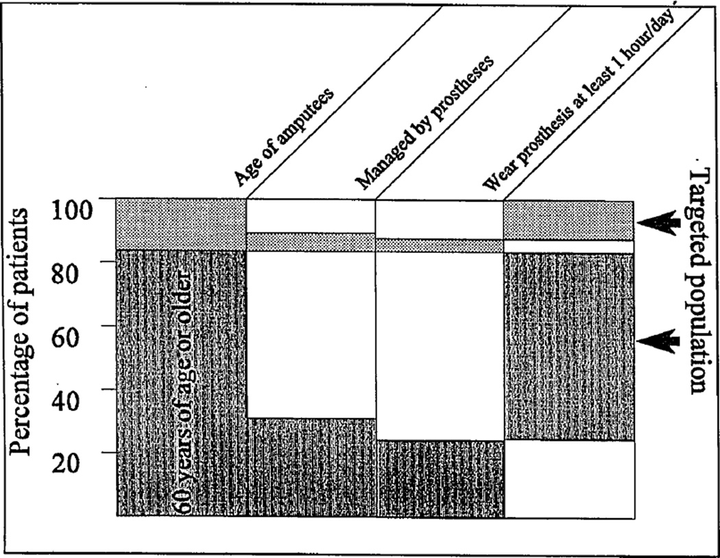
A prosthetic leg may or may not provide an appropriate level of rehabilitation (3). The necessity for better leg prostheses is evident when analyzing the outcome of prosthetic management in the United States and Canada (4,5). Studies reveal 78 percent of all transfemoral amputees never wear prostheses or use them no more than one hour per day (see Figure 1); 40 percent of transtibial amputees do not wear prostheses (1,6,7).
Figure 1.
Use of prostheses in leg amputees. “Targeted population” means 78 percent of all amputees who were regarded as prosthetic failures or were not considered as prosthesis users.
People typically reject a prosthesis because of physical discomfort—more specifically, pain in the residual limb during ambulation. Hermodsson et al. (8) and Helm and Pandian (9) report approximately 50 percent of individuals who are transtibial amputees due to vascular causes and 33 percent of individuals who are transtibial amputees due to trauma reportedly suffer from residual-limb pain.
Pain is a physiological message signalling that stresses are close to the threshold and tissues could be damaged. Amputees develop compensatory gait strategies to avoid pain and protect the residuum. The most vulnerable part of the residuum is the skin, and problems of residual-limb skin integrity often appear immediately after surgery. Analysis of transtibial amputation cases showed 16 percent failed to heal correctly and had to be reamputated at a higher level (10). Even after patients begin using a definitive prosthesis, skin problems still constitute a large percentage of the complications contributing to rejection of prostheses (11,12).
Researchers have studied extensively the dependence of residuum-socket interface on residual-limb conditions, fit of the socket, liners, types of suspension and alignment (13,14); measured normal and shear stresses between residuum and socket during gait (15,16); and requested a more anatomically correct ankle based on the influence of prosthetic design on residual-limb/socket interface (17). However, no specific design modifications have been recommended.
The author developed a mathematical model of residual-limb/socket interface (18) to predict stresses on critical residuum zones depending on the moment of resistance in prosthetic joints. The model reveals that when the moment of resistance in the prosthetic ankle has an approximately normal pattern, provided by the experimental rolling-joint foot (RJ foot) (19), stresses on anterior-distal and posterior-proximal zones of the residuum are decreased at least 30 percent compared to current prostheses with their different moment-of-resistance patterns. A comparative gait analysis of four unilateral transtibial amputees indicated that when using the RJ foot, some gait characteristics were closer to normal than with the SACH foot. The term “prosthetic gait synergy” has been defined (20) to determine influence of prosthetic design on an amputee’s performance.
Ultimately, alignment is a setting of relative orientation (e.g., angles and offsets) of the prosthetic socket, pylon and prosthetic foot. Both angles between prosthetic components and relative offsets change lever arms for moments of forces associated with gait. A control over moment of resistance in prosthetic joints, discussed in this article, can be considered an addition to that general moment technique for individual tuning of prostheses. Another part of the moment technique is the traditional alignment.
The importance of the moment of resistance in the prosthetic ankle was demonstrated in a study conducted by the Veterans Administration to link the moment of resistance in the SACH foot with patient characteristics (21). A “load-deformation” test was developed, which provided three grades of prosthetic heel stiffness that should be recommended according to patient weight/activity level. The suggestion was made to develop a standard for articulated prosthetic feet in which the “ankle moment versus angular displacement” would be used as a means of classification and prescription (22). However, at that time no existing prosthesis provided a normal-like pattern of such dependency to support this request. The development of the RJ foot (19) may provide an opportunity to complete the job proposed many years ago by independent researchers.
Prosthetic Gait Synergy Defined
The generic term “synergy” means combined action. When applied to motor control, and specifically to normal gait, it is used to describe a repeatable, coordinated pattern of muscle activity or body kinetics. Synergistic movements require minimal neural control and therefore appear to be the modules of automatic performance (23). The existence of synergies supports the physiological perception that not all degrees of freedom in the human body have to be independently controlled in gait; instead, a few key parameters determine corresponding subprograms of locomotion.
Saunders et al. (24) conducted a study wherein six determinants, or synergies, of normal gait were selected; this study serves as an example of synergistic representation of normal gait. These determinants were compared with amputee gait deviations to yield a stable set of parameters (13,14,22), which can be called “prosthetic gait synergy” (PGS).
By definition, prosthetic gait synergy represents the best possible gait pattern of an amputee with a given type of prosthesis/prostheses. Not every deviation from normal gait is considered a component of the prosthetic gait synergy—only deviations that remain apparent after proper residuum conditioning, socket fit, and prosthesis alignment and adjustment, and after the amputee becomes accustomed to the prosthesis (25–27).
The definition of prosthetic gait synergy is based on an assumption that the ideal residual-limb conditioning, socket fit, and prosthesis alignment and adjustment are available, which is an approximation of reality. However, it enables us to focus on the engineering aspects of prosthetic design to decrease the differences between prosthetic gait synergy and normal gait synergy.
Prior to the 1990s, many in the O&P field believed it might not be necessary to normalize gait pattern in amputees. A relatively good level of rehabilitation in transfemoral amputees can be found when a single-axis prosthetic knee without a brake is used in combination with voluntary control of knee stability (28). The technique of voluntary control of knee stability requires a generation of the hip extension moment, which pulls the heel backward from the time of initial heel contact to the foot flat event. That action produces a horizontal component of ground reaction with forward orientation in early stance, opposite to the backward orientation seen in normal gait. As a result, the prosthetic knee is secured in the fully extended position during the load response phase as opposed to approximately 15 degrees of normal knee flexion, providing a specific gait pattern distinctively distant from the normal one.
Two factors, however, suggest attempts to normalize gait pattern in amputees must continue. The first is a number of reports about secondary complications due to asymmetrical gait kinematics and kinetics in unilateral amputees, or poor shock absorption and extra compensatory movements in bilateral amputees (13,29–31). Second, the development of energy-storing prosthetic feet (32–38) and knees with stance flexion (39,40) offer hope that improved engineering capabilities can aid in further advancement of amputee gait pattern.
Effect of Prosthesis Alignment and Adjustment on Gait
Prosthesis alignment and adjustment as a way to maximize patients’ comfort and gait performance have been investigated and established (41,44); these issues constitute a necessary element of daily work in prosthetic facilities. Detailed instructions have been developed for assessing gait in each of the stride phases and for corresponding measures to be taken by a prosthetist to benefit a patient (28,45). Czerniecki (46) developed a summary of procedures and suggested considering the residuum-socket interface as a virtual joint that needs to be stabilized by the external moments. Since moments from the socket to the residuum in all three planes depend on lever arms of ground reactions, proper alignment may minimize such moments and consequently reduce normal and shear stresses on the residuum. To illustrate that approach, we generated Table A, where gait deviations frequently observed in transtibial amputees are presented against possible sources of malalignment.
Table A.
Typical causes of malalignment in transtibial amputees’ prostheses.
|
Malalignments
in coronal plane |
Gait deviations | |||
| Too narrow base of gait |
Too wide base of gait |
Inversion of foot |
Eversion of foot |
|
| Inset of prosthetic foot relative to socket | X | X | ||
| Outset of prosthetic foot relative to socket | X | X | ||
| Varus of socket relative to shank | X | X | ||
| Valgus of socket relative to shank | X | X | ||
| Excessive internal rotation of foot | X | X | ||
| External rotation of foot | X | X | ||
|
Malalignments
in sagittal plane |
Gait deviations | |||
| Excessive knee flexion |
Drop-off | Reduced knee flexion or knee hyperextension |
Shortened intact step |
|
| Posterior translation of socket relative to shank | X | X | ||
| Anterior translation of socket relative to shank | X | X | ||
| Excessive socket flexion relative to shank | X | X | ||
| Excessive socket extension relative to shank | X | X | ||
| Excessive foot dorsiflexion | X | X | ||
| Excessive foot plantarflexion | X | X | ||
In light of the definition provided, the PGS appears to be the best possible outcome of prosthesis alignment and adjustment since these procedures are performed over the given prosthesis within a manufacturer’s specification. The practical implication is developing a PGS closer to normal gait synergy requires a different prosthetic design, including socket, suspension, connectors, adapters and joint units. To proceed with such a task, criteria for selection or development must be established. It is suggested the criterion by which prosthetic joints have to be compared, distinguished and selected would be the moment of resistance to angulation.
Influence of Moment of Resistance in Prosthetic Ankle on Gait
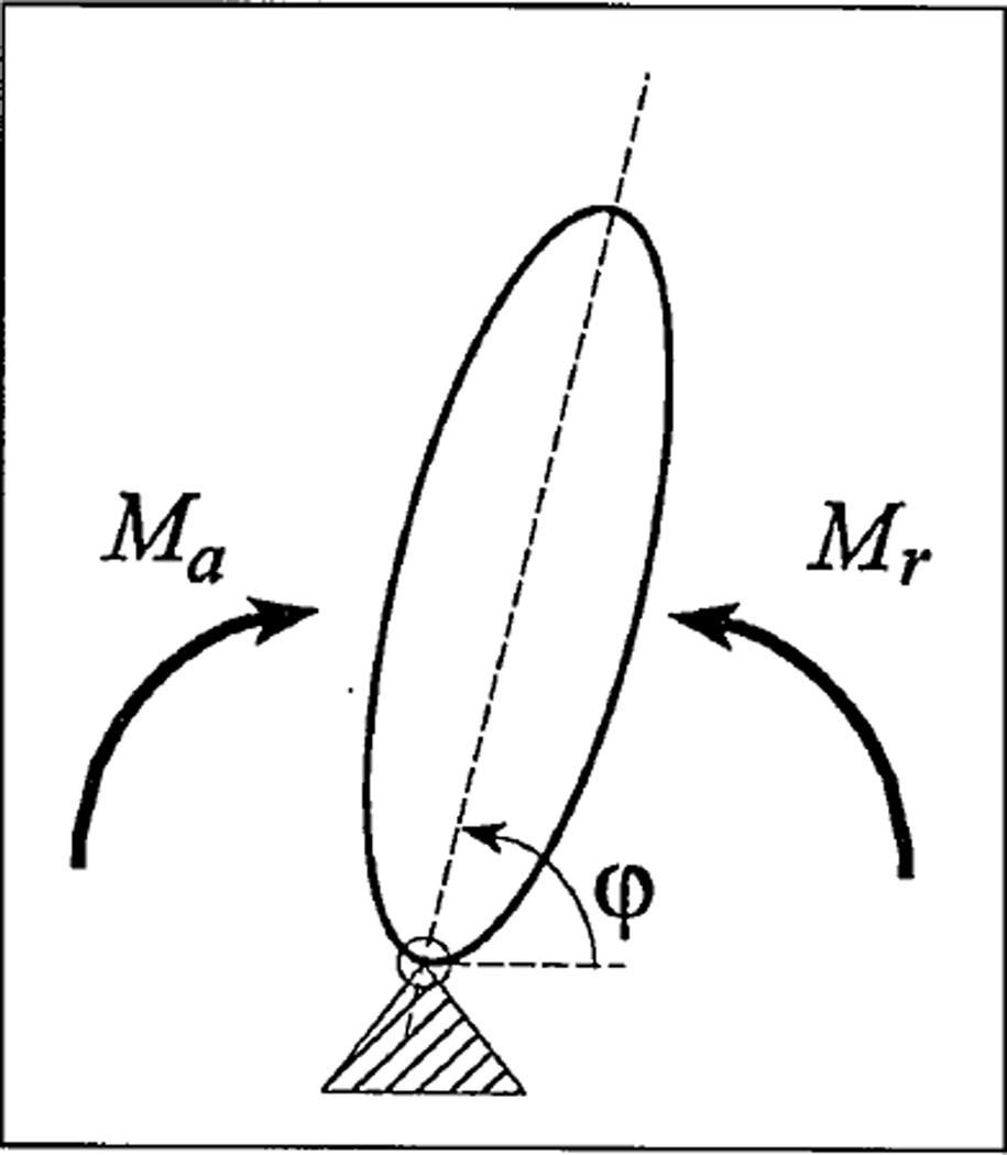
The moment (or torque) is defined as a rotational potential of the forces acting on a joint. During balance, a resultant moment Mr of forces causing rotation at the angle φ equals the resultant moment Ma of forces providing resistance to that rotation (see Figure 2). In motion, Mr is greater than Ma, and the exact difference is given by Newton’s second law for rotation by Equation (1), where I is the moment of inertia of the angulating link, and φ̈ is its angular acceleration.
| (1) |
Figure 2.
Resultant moment Mr of forces causing rotation at the angle φ and resultant moment Ma of forces providing resistance to that rotation. Reactions in joint are not accountable since their lever arms relative to the joint equal zero.
Muscles affecting a joint’s articulation as well as the force of gravity may contribute either to Ma or to Mr depending on the body configuration during different phases of locomotion. For example, during most of the stance phase, foot plantarflexors provide resistance (Ma) to dorsiflexion rotation in the ankle; after heel rise they cause active plantarflexion (Mr). The same is true for body weight mg and ground reactions vector R since these forces change orientation relative to the joint’s center from anterior to posterior several times during the stride cycle (47,48).
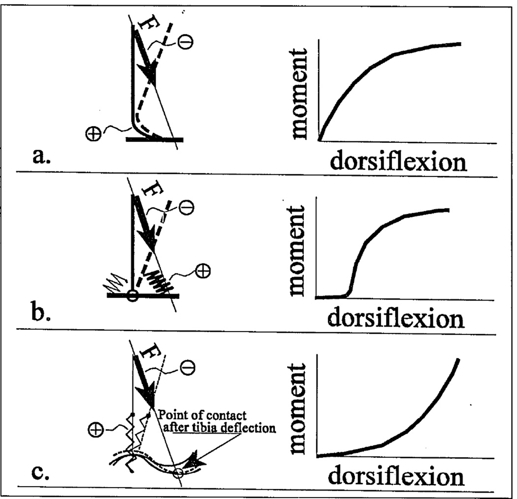
Moment Ma of resistance in a sound ankle joint during foot dorsiflexion is shown in Figure 3c; it correlates to the pattern of the foot flexor performance (EMG signal versus stance events) (49). The mostly concave shape of the curve indicates initiation of dorsiflexion does not encounter a large amount of resistance from the plantarflexors. It has been shown (50) that in all available prosthetic feet, the elastic elements are compressed or bent in convex patterns (see Figures 3a and 3b), which are opposite from the concave pattern seen in the biological ankle.
Figure 3.
a. (Adapted from Reference 50, with permission.) The convex pattern of the moment of resistance to deflection during the dorsiflexion period for prosthetic mechanisms of bending class, such as the SACH foot. Figure 3b. The convex pattern of the moment of resistance to deflection during the dorsiflexion period for the uniaxial foot. Figure 3c. The convex pattern of the moment of resistance to deflection during the dorsiflexion seen in the biological ankle and in the cam-rolling mechanism of the RJ foot.
The concave pattern of resistive moment seen in the biological ankle has been produced by the rolling or higher-pair mechanism (see Figure 3c) using the technique published elsewhere (51). Corresponding prototypes of the RJ foot prosthesis were manufactured and tested (52). The biomechanical study of four unilateral amputees revealed normalization of stride parameters (see Table B) when using the RJ foot instead of the SACH foot (53).
Table B.
Averaged temporal components of stance phase, percentage of stance phase and asymmetry indices (prosthetic side/contralateral side) of four unilateral transtibial amputees with SACH foot and RJ foot.
| Temporal components of stance phase |
Normal1 subjects |
Contralateral side | Prosthetic side | Asymmetry
index Prosthet/Contralat |
Asymmetry
index Contralat/Norm |
||||
|---|---|---|---|---|---|---|---|---|---|
| SACH | RJ foot | SACH | RJ foot | SACH | RJ foot | SACH | RJ foot | ||
| Heel strike—fool flat | 17.9% | 12.77% | 20.00% | 28.85% | 12.24% | 2.26 | 0.61 | 0.71 | 1.12 |
| Heel strike—heel rise | 55.2% | 48.94% | 55.56% | 28.85% | 59.18% | 0.59 | 1.07 | 0.89 | 1.01 |
| Heel rise—toe off | 26.9% | 38.29% | 24.44% | 42.30% | 28.58% | 1.10 | 1.17 | 1.42 | 0.91 |
| Average of asymmetry indices | 1.32 | 0.95 | 1.01 | 1.01 | |||||
| Standard deviation of the asymmetry indices | 0.86 | 0.30 | 0.37 | 0.10 | |||||
Adapted and modified from Reference 24, Table 4, with permission.
Temporal Data
Differences in temporal components of the prosthetic and contralateral stance phase were found to be substantial for the gait of subjects with SACH feet. For the RJ foot the differences were not significant at the 5-percent level with a two-sample t-test. (See the asymmetry index—prosthet/contralat, Table B.)
Comparison with published data on normal subjects (22) showed the RJ foot provided a symmetry of “normal” type rather than created a specific new “prosthetic” symmetry (see asymmetry index—contralat/norm). Of the three stance components investigated, the closest to normal pattern while wearing the RJ foot was the “foot-flat/heel-rise” period (shadowed cells in Table B). During that period, the foot provides stable support for tibial angular advancement relative to the ankle (48). All subjects indicated such a restoration happened without additional stresses on the residual limb from the socket.
Existing Knee Performance
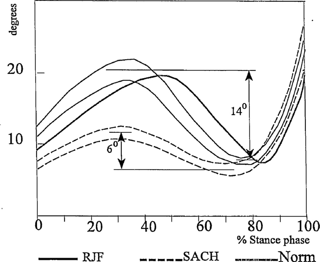
The knee angle of the involved leg in transtibial amputees during the stance phase of walking with both the SACH foot and RJ foot is shown in Figure 4a. The knee range of motion increased with the RJ foot compared to the subjects’ own prostheses (14±2.1 degrees versus 6±1.1 degrees) and was closer to normal values. This result was in accord with an initial study of one bilateral amputee (19). It also confirms the initial hypothesis that the more compliant higher pair ankle in the RJ foot provided mechanical conditions for more normal synergetic bending in the knee and ankle without causing a loss of balance.
Figure 4.
Averaged knee angles in the existing joint of involved leg in four transtibial subjects during gait with the RJ foot and SACH feet. The lines represent one standard deviation on either side of the mean. A biological knee angle is shown for comparison.
Moment of Resistance in the Prosthetic Knee
To prevent collapsing during weight acceptance, prosthetic knee mechanisms usually are designed without the option of flexion in early stance (28,55–58). However, a desire to provide the stance flexion seen in normal gait has resulted in three recent knee mechanisms of that type: the Otto Bock 3R60 EBS Kneea, the Blatchford Endoliteb and the Total Kneec.
While new knee mechanisms demonstrate up to 15 degrees of flexion under the load equivalent to body weight in mechanical tests, none show a stance-knee angle greater than 5 degrees during actual amputee gait (59). A combination of two reasons may explain this.
First, these knees have a concave pattern “moment of resistance versus stance-knee angle” similar to commercially available feet (see Figures 3a and 3b), which means initiation of knee flexion requires an excessive load, which translates to excessive pressure on the residuum. To avoid pain associated with such an excessive pressure, amputees are advised not to execute the full range of motion technically possible with the advanced prosthetic knee joints.
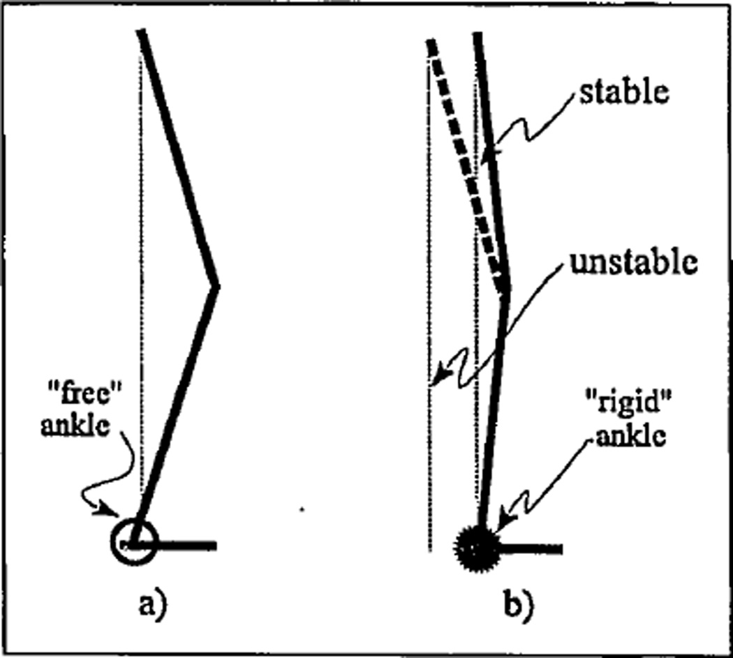
Second, when a compliant knee joint is assembled with a “rigid” ankle, the patient cannot bend his or her knee properly because of difficulty maintaining balance. This synergetic relationship for standing is depicted in Figure 5a, where a linkage configuration represents a normal-type combination of initially compliant ankle and knee. It is seen from Figure 5b that a “rigid” ankle causes an aft shift of the body’s center of mass, which could lead to loss of balance if the knee is bent at its full range of motion (15 degrees). That explains why a patient must limit knee bending to prevent falling backward when the ankle is “rigid.” In gait, that synergy is more complex since the weight-loading event coincides with a vertical position of a shank, and a dynamic factor is apparent (48,60).
Figure 5.
Synergetic range of motion in knee with “free” (a) and “rigid” (b) ankle.
A direct request for the design of prosthetic foot/ankle units with true biological plantarflexion within the ankle mechanism for transfemoral prostheses was justified (55) since such a feature would provide better absorption of the shock and moment generated at heel strike, thereby decreasing potential knee instability.
A Model of the “Residuum-Socket” Interface
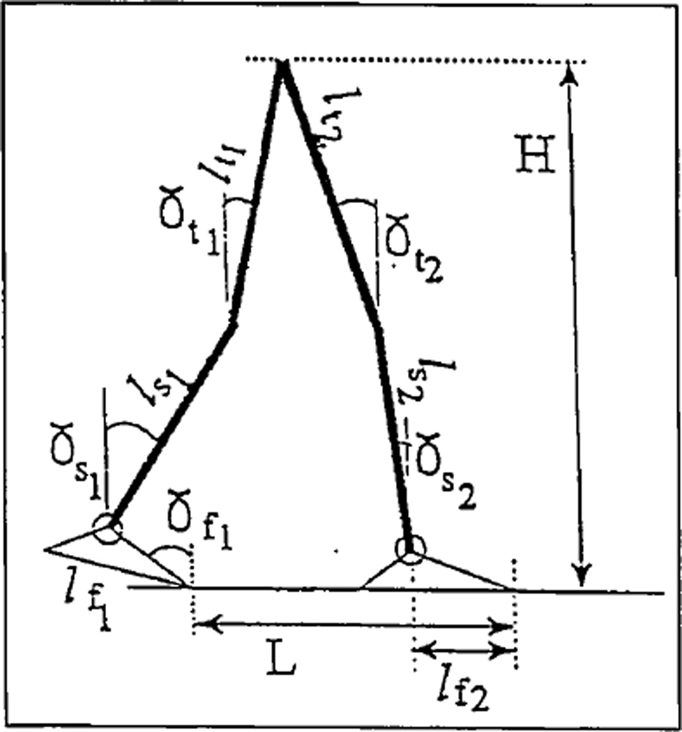
Kinematic and kinetic components of the model are illustrated in Figures 6–8. The model is a planar open chain of six weightless rods: two feet of lengths lf1 and lf2; two shanks ls1 and ls2; and two thighs lt1 and lt2. Angles between these elements and the vertical are γfi, γsi and γti (i=1,2), respectively (see Figure 6).
Figure 6.
Kinematics of the model.
Figure 8.
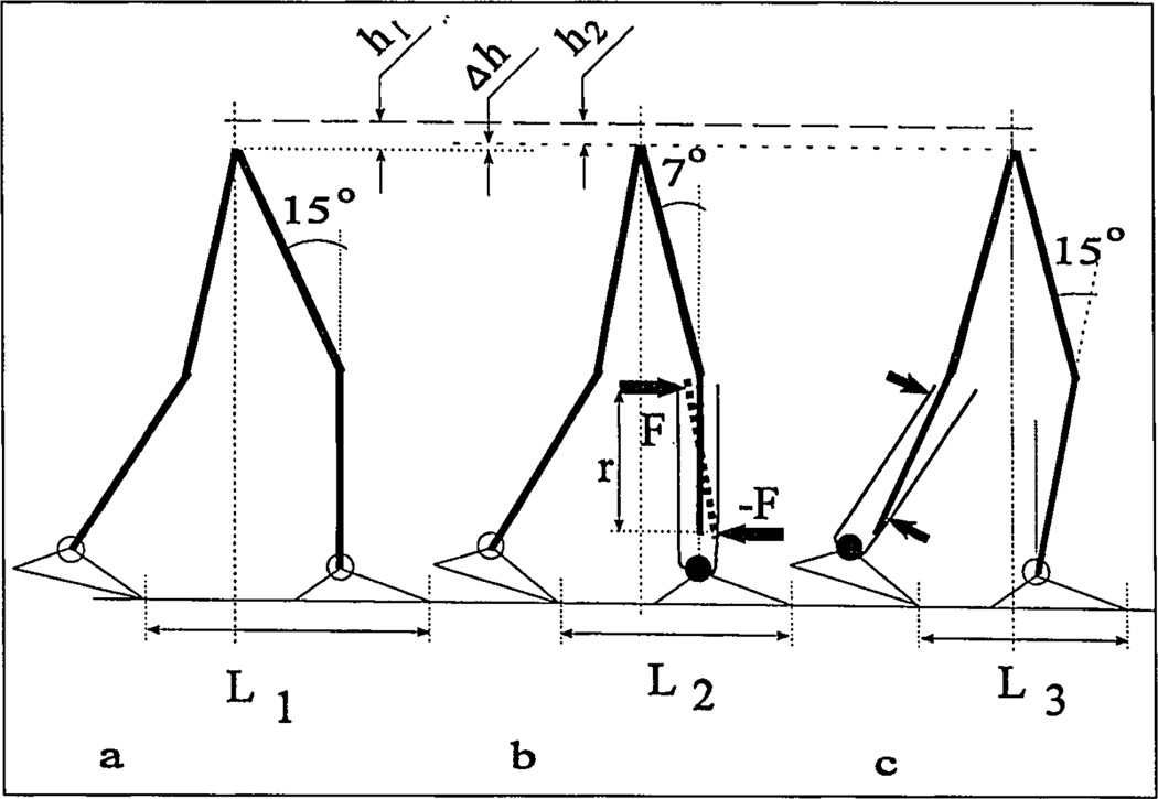
Normal (a) and prosthetic (b,c) gait synergies.
It is assumed that center of mass (COM) is located at the central joint, simulating projection of both hip joints. Step length L and height H of the COM are given by Equations (2):
| (2) |
There are certain anthropomorphic restraints on the values of the 14 parameters. When 11 of them are specified, the other three can be calculated from Equations (2). Feet, shanks and thighs are recommended to be paired-equal length and should not be considered variables, but constants, which reduces the number of undetermined parameters to five. Additionally, two constraints were derived based on gait analysis data regarding stance events.
For the maximal load acceptance configuration, the foot of the fore leg is assumed to be in flat position (γf2 = 90 degrees), and its shank is vertical (γs2 = 0 degrees). Thus, any three parameters from L, H, γf1, γs1, γt1 and γt2 can be taken as input for Equations (2) while the remaining three parameters will be explicitly found. Vertical position of the shank at the time of maximal loading and free ankle mobility around this shank position have been documented during normal gait (48). It is hypothesized that both components could be beneficial for an amputee when incorporated into his or her gait pattern.
| (3) |
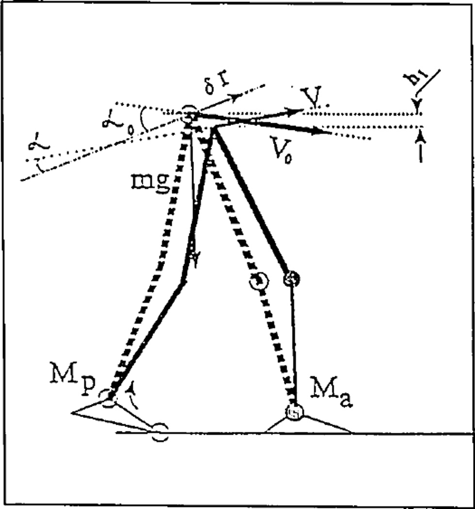
The way the free ankle reduces the propulsive moment can be seen in Figure 7 and Equation (3), derived from the theorem of kinetic energy change (61). In Equation (3), A (Mp) is the work of internal propulsive “push-off” moment Mp; A (Ma) is the work of internal moment Ma of resistance in ankle joint of the fore leg; (m/2) (V0 cosα0)2 is the kinetic energy of a model in initial position; (m/2) (V cos α)2 is the kinetic energy of a model in final position; and mgh1 is negative work of the force of gravity. Angles α0 and α are between the direction vector of virtual displacement δr and the vectors V0 and V, respectively. It can be seen from Equation (3) that the smaller resistive moment Ma and the smaller propulsive “push-off” moment Mp must be for the same outcome.
Figure 7.
Dynamic effect of the moment of resistance Ma in the ankle of the foreleg on the propulsive moment Mp in the ankle of the contralateral leg.
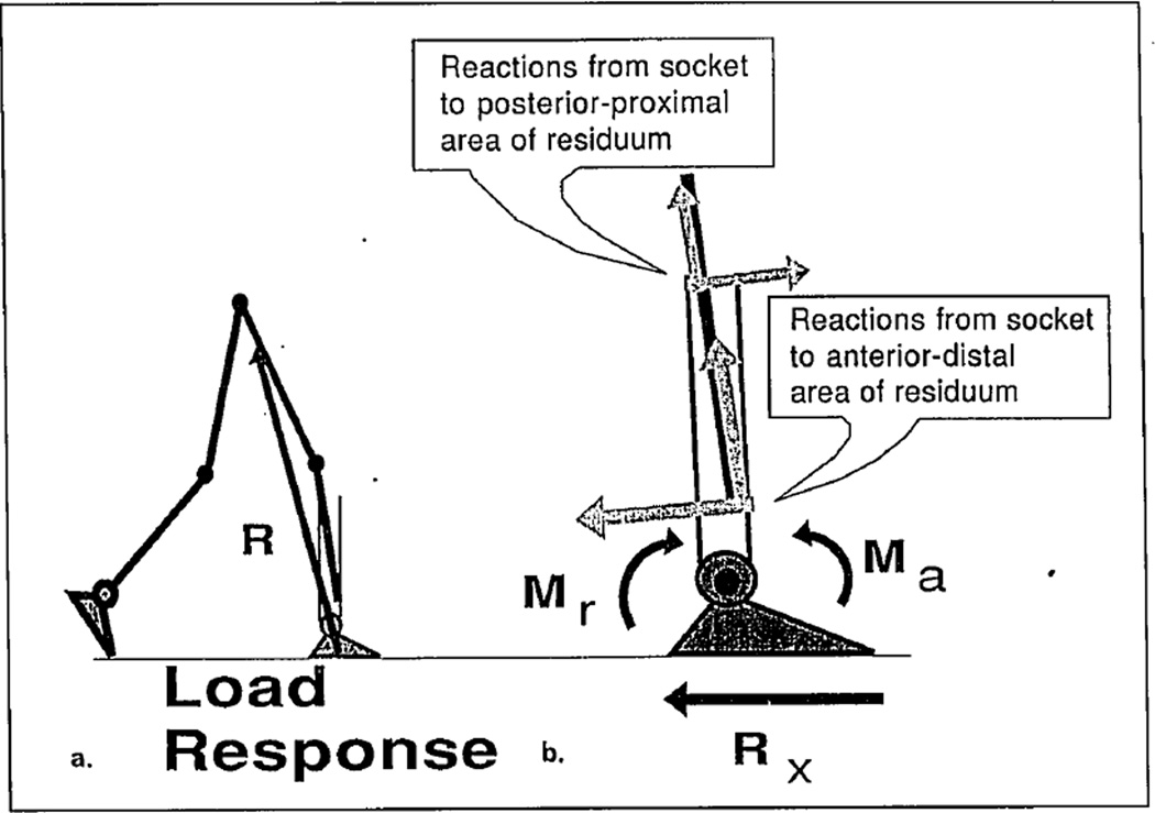
The effect of the resistive moment Ma = F × r on “residuum-socket” interface in transtibial amputees is simulated in Figure 8, where couple forces ±F are applied from the socket to the residuum. The forces ±F provide normal stresses on the residual limb in addition to shear stresses derived from the axial load as explained by Pearson (62).
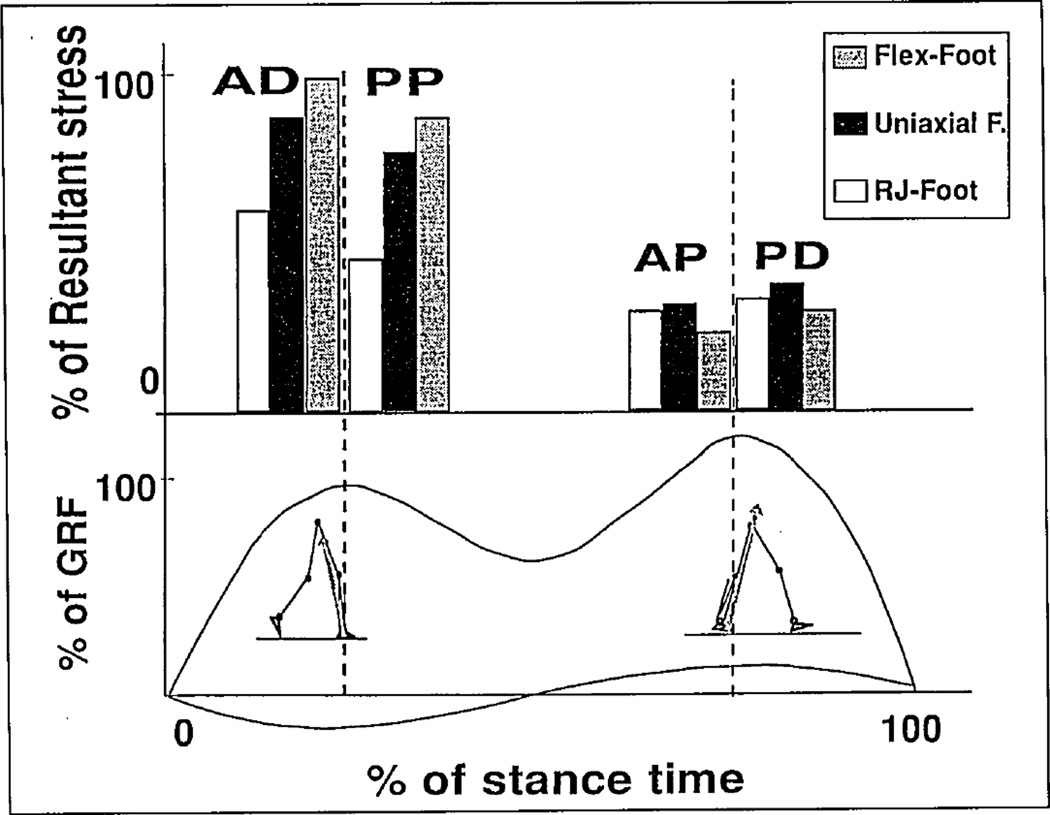
Computations of resultant stresses have been conducted at the load-response phase of stance (see Figure 9a) and at the heel-rise event when body configuration is determined from Equations (2) and three types of moment of resistance are used (see Figure 3). The corresponding free body diagram in Figure 9b yielded stresses for the following zones of the residuum: For the load-response phase, the anterior-distal and posterior-proximal zones were considered; for the heel-rise event, the zones of interest were anterior-proximal and posterior-distal (see Figure 10). The selected zones experience major stresses during these phases of stance, which coincide with two maximums of the ground-reaction force (GRF) (16).
Figure 9.
Reactions from socket to posterior-proximal and anterior-distal areas of the residuum at the load response phase of stance. These reactions are opposite to the forces generated by the residuum and applied to the socket to rotate the prosthetic ankle joint, and their action is equivalent to the moment Mr. The greater the moment of resistance Ma, the greater is the demand for the residuum action (with corresponding reactions from the socket to the residuum). Rx is the horizontal component of the ground-reaction force.
Figure 10.
Computed stresses on the anterior-distal and posterior-proximal zones of the residuum at the load response phase and on the anterior-proximal and posterior-distal zones for heel-rise event. The selected zones experience major stresses during these phases of stance that coincide with two maximums of the GRF.
The resulting computations agreed with the conclusions from the study (16) and with the conclusion that the load-response phase is three to five times more challenging for the residuum than the heel rise. The latter fact may seem surprising since the absolute values of both peaks of the GRF are close to each other. The model, however, explains the GRF lever arm relative to a virtual joint substituting the residuum-socket interface is greater at the load-response phase (see Figure 9) than at the heel rise. Correspondingly, the difference in moments Ma from socket to residuum is present at these phases.
The chart in Figure 10 demonstrates normal stresses computed for three major classes of prosthetic ankle mechanisms. At the load response, the uniaxial foot demonstrated a 10-percenl reduction in stresses relative to the Flex-Foot® (100 percent) while the RJ foot provided at least 30-percent reduction. At heel rise, all three classes of mechanisms demonstrated close data with the smallest stresses with the Flex-Foot. The overall conclusion of model computation was that the RJ foot has a theoretical advantage in terms of potential to reduce stresses on the residuum during a critical phase of stance.
Prosthetic Gait Synergy as a Means of Pain Prevention
Amputees are advised to avoid additional stresses from the resistive moment Ma in the prosthetic ankle as well as overloading the residual limb in the axial direction. To decrease vertical load, an amputee should decrease his or her walking speed and shorten the step of the involved, and to an even greater extent, the uninvolved leg. To minimize the effect of resistive moment Ma, an amputee should try to decrease the lever arm of the GRF vector affecting the virtual joint residuum-socket. Both components of the prosthetic gait synergy, called “pain preventive,” are well-documented (43,63).
Equations (2) were used to calculate knee angle at the moment of maximal load acceptance for normal gait (see Figure 8a) and for the involved (see Figure 8b) and uninvolved (see Figure 8c) legs in prosthetic (unilateral, transtibial) gait. Step lengths L1, L2 and L3 and angles γf1 were averaged from the biomechanical data available (26,63). In the prosthetic step, γs2 = 0 degrees, which resulted in a 15-degree knee angle. For the uninvolved step, the shank angle was calculated since the knee angle is known to be similar to normal. It resulted in advanced orientation of the uninvolved shank, in contrast with the vertical position seen in both normal and the involved leg’s step.
Both results were confirmed by a recent biomechanical study (53). It was hypothesized that in amputee gait, the normal gait synergy is replaced by the PGS, where prevention of residual-limb pain plays a dominant role and determines deviations from the norm.
As seen in the residuum-socket interface model, attempts to avoid bending the prosthesis at the ankle joint cause a decrease in knee angle and in prosthetic step length. The model also helps explain why the normal-type resistive characteristics of the RJ foot normalize gait in transtibial amputees.
It appears that the almost-free articulation of the RJ foot around the vertical position of the shank would allow the amputee, without changes in gait kinematics, to decrease the stresses associated with the necessity to bend the prosthesis in the ankle zone.
The other option would be to normalize (increase) prosthetic step length and knee angle without any additional increase in residual-limb stresses.
Discussion
In normal walking, the maximum knee flexion (15 degrees) during the stance phase occurs at the end of the loading phase when the tibia is fully upright and both foot flexors and extensors are not fired (24,48). Both vertical position and free articulation in the ankle eliminate bending moments on the tibia, which prevents damage during maximal load acceptance. The bending moment of that origin acts on the system residuum-socket in amputee gait, resulting in additional normal and shear stresses on the residual limb. Due to the “rigid” ankle in existing prostheses, this moment is unavoidable.
The appropriate compensatory feature controlled by an amputee is an intuitive shortening of the step and lowering speed (65) to decrease maximal load or the first peak of the ground-reaction force (vertical and horizontal components). Decreased knee angle probably is a visual indication of less load transmitted to the residual limb (due to shortening step and lowering the speed of ambulation). This explains a strong correlation between reduced knee angle during stance phase (average 7 degrees vs. 15 degrees in norm) and the decreased step and stride length (43).
Approximately normal compliance of prosthetic joints, in combination with the vertical position of the amputee’s shank, minimizes the moment from the anterior-posterior forces of socket reactions applied to the residual limb. In transtibial amputees, a biologically compliant ankle unit would eliminate the necessity for 5-degree dorsiflexed orientation of the pylon, which is recommended to facilitate the roll-over. The biomechanical essence of that alignment procedure is shortening the GRF vector lever arm relative to the virtual joint residuum-socket.
In transfemoral amputees, a combination of biologically compliant prosthetic ankle and knee units also would facilitate the gait due to the self-alignment feature of such units.
Mechanical outcome of any biological and prosthetic joint can be characterized by a moment of resistance to angulation in each of the three planes. Inclusion in analysis of a virtual joint, which substitutes for the residuum-socket interface, simplifies a decision-making process in design, fabrication and alignment of prostheses. As examples of that “moment” approach, one can consider development of a patellar-tendon-bearing socket for transtibial prostheses (66), a quadrilateral socket for transfemoral prostheses (55) and a generalized alignment technique (28,41,44–46). This approach will help deal with a growing number of adjustment mechanisms and eventually benefit patients.
Acknowledgments
This work was supported in part by NIH Institutional Research Training Grant #HD 07415, NIH/NIAMS/SBIR Grant #1R43AR43290-01, and the Ohio Willow Wood Co., Mount Sterling, Ohio.
Biomechanical evaluation of the RJ foot was conducted at the Amputee Clinic, New England Sinai Hospital and Rehabilitation Center, Stoughton, Mass., with assistance from United Prosthetics Inc., Dorchester, Mass.
Technical support for the gait study was provided by Peak Performance Technologies in Englewood, Colo., and Reebok International Ltd. in Stoughton, Mass.
Footnotes
Otto Bock Orthopedic Industries Inc., 2000 Xenium Lane, N., Minneapolis, MN 55441.
Endolite North America, 105 Westpark Road, Centerville, OH 45459.
Century XXII Innovations Inc., 1331 Horton Road, Jackson, MI 49203.
References
- 1.Gailey RS, Wenger MA, Raya M, Kirk N, Erbs K, Spyropoulos P, Nash MS. Energy expenditure of transtibial amputees during ambulation at self-selected pace. Pros Orth Intl. 1994;18:84–91. doi: 10.3109/03093649409164389. [DOI] [PubMed] [Google Scholar]
- 2.Torres MM. Incidence and causes of limb amputations. Phys Med Rehab: State of the Art Rev. l994;8(1):1–8. [Google Scholar]
- 3.Gottschalk FA, Stills M. The biomechanics of AK amputation. Pros Orth Int. 1994;18:12–17. doi: 10.3109/03093649409164665. [DOI] [PubMed] [Google Scholar]
- 4.Sapp L, Little CE. Functional outcome in a lower-limb amputee population. Pros Orth Intl. 1995;19:92–96. doi: 10.3109/03093649509080350. [DOI] [PubMed] [Google Scholar]
- 5.Johnson VJ, Kondziela S, Gottschalk FA. Pre- and postamputation mobility of transtibial amputees: correlation to medical problems, age and mortality. Pros Orth Intl. 1995;19:159–164. doi: 10.3109/03093649509167999. [DOI] [PubMed] [Google Scholar]
- 6.Hoaglund FT, Jergsen HE, Wilson L, Lamoreux LW, Roberts R. Evaluation of problems and needs of veteran lower-limb amputees in the San Francisco Bay Area during the period 1977–1980. J Rehab Res Devel. 1982;19(2):57–71. [PubMed] [Google Scholar]
- 7.Glattly HW. A statistical study of 12,000 new amputees. South Med J. 1984;57:1,373–1,378. doi: 10.1097/00007611-196411000-00024. [DOI] [PubMed] [Google Scholar]
- 8.Hermodsson Y, Ekdahl C, Persson BM, Roxendal G. Gait in male transtibial amputees: a comparative study with healthy subjects. Pros Orth Int. 1994;18(2):68–77. doi: 10.3109/03093649409164387. [DOI] [PubMed] [Google Scholar]
- 9.Helm PA, Pandian G. Prevention of amputation. Phys Med Rehab: State of the Art Rev. 1994;8(1):9–17. [Google Scholar]
- 10.Falsie-Jensen N, Christensen KS. A model for prediction of failure in amputation of the lower limb. Dan Med Bull. 1990;37:283–286. [PubMed] [Google Scholar]
- 11.Thompson RG. Complications of lower-extremity amputations. In: Sarmiento A, editor. Amputation surgery and prosthetics. Orthop Clinics of N Amer. 3. Vol. 3. 1972. pp. 323–338. [PubMed] [Google Scholar]
- 12.Levy SW. Skin problems of amputees. St. Louis: Warren H. Green; 1983. [Google Scholar]
- 13.Esquanazi A. Analysis of prosthetic gait. Phys Med Rehab: State of the Art Rev. 1994;8(1):201–220. [Google Scholar]
- 14.Fernie GR. Biomechanics of gait and prosthetic alignment. In: Kostuik JP, editor. Amputation surgery and rehabilitation, the Toronto experience. New York: Churchill Livingstone; 1981. pp. 259–265. [Google Scholar]
- 15.Sanders JE, Daly CH, Burgess EM. Interface shear stresses during ambulation with a below-knee prosthetic limb. J Rehab Res Devel. 1992;29(4):1–8. doi: 10.1682/jrrd.1992.10.0001. [DOI] [PMC free article] [PubMed] [Google Scholar]
- 16.Sanders JE, Daly CH, Burgess EM. Clinical measurement of normal and shear stresses on a transtibial stump: characteristics of wave-form shapes during walking. Pros Orth Intl. 1993;17:38–48. doi: 10.3109/03093649309164353. [DOI] [PubMed] [Google Scholar]
- 17.Sanders JE, Daly CH. Normal and shear stresses on a residual limb in a prosthetic socket during ambulation: comparison of finite element results with experimental measurements. J Rehab Res Devel. 1993;30(2):191–204. [PubMed] [Google Scholar]
- 18.Pitkin MR. Proceedings, 23rd Annual Meeting & Scientific Symposium, American Academy of Orthotists and Prosthetists. San Francisco: 1997. Model of residuum-socket interface; pp. 21–22. [Google Scholar]
- 19.Pitkin MR. Synthesis of the cycloidal mechanism of a prosthetic ankle. Pros Orth Intl. 1996;20:159–171. doi: 10.3109/03093649609164438. [DOI] [PMC free article] [PubMed] [Google Scholar]
- 20.Pitkin MR. Proceedings, XVIth Congress of the ISB. Tokyo, Japan: 1997. Pain preventive gait synergy hypothesis in leg amputees. (accepted) [Google Scholar]
- 21.Veterans Administration Prosthetic Center. Standards and specifications for prosthetic foot/ankle assemblies. Washington, D.C.: Veterans Administration; 1973. (VAPC-L-7007-2) [Google Scholar]
- 22.Goh JCH, Solomonidis SE, Spence WD, Paul JP. Biomechanical evaluation of SACH and uniaxial feet. Pros Orth Intl. 1984;8:147–154. doi: 10.3109/03093648409146077. [DOI] [PubMed] [Google Scholar]
- 23.Bernstein NA. Headington Hill Hall. Oxford: Pergamon Press Ltd.; 1967. The coordination and regulation of movements. [Google Scholar]
- 24.Saunders JBDeCM, Inman VT, Eberhart HD. The major determinants in normal and pathological gait. JBJS. 1953;35-A:545–558. [PubMed] [Google Scholar]
- 25.Breakey J. Gait of unilateral below-knee amputees. Orth Pros. 1976;30(4):17–24. [Google Scholar]
- 26.Robinson JL, Smidt GL, Arora JS. Accelerographic, temporal and distance gait factors in below-knee amputees. Phys Ther. 1977;57(7):898–904. doi: 10.1093/ptj/57.8.898. [DOI] [PubMed] [Google Scholar]
- 27.Zuniga EN, Leavitt LA, Calvert JC, Canzoner J, Peterson CK. Gait patterns in above-knee amputees. Arch Med Rehab. 1972;53:373–382. [PubMed] [Google Scholar]
- 28.Radcliffe CW. Four-bar linkage prosthetic knee mechanisms: kinematic, alignment and prescription criteria. Pros Orth Intl. 1994;18:159–173. doi: 10.3109/03093649409164401. [DOI] [PubMed] [Google Scholar]
- 29.Lemaire ED, Fisher R. Osteroarthritis and elderly amputee gait. Arch Phys Med Rehab. 1994;75:1,094–1,099. doi: 10.1016/0003-9993(94)90084-1. [DOI] [PubMed] [Google Scholar]
- 30.Radin EL, Yang KH, et al. Relationship between lower-limb dynamics and knee-joint pain. J Orthop Res. 1991;9(4):398–405. doi: 10.1002/jor.1100090312. [DOI] [PubMed] [Google Scholar]
- 31.Engsberg JR, Lee AG, Tedford KG, Harder JA. Normative ground reaction force data for able-bodied and transtibial amputee children during walking. Arch Phys Med Rehab. 1991;72:657–661. [Google Scholar]
- 32.Hittenberger DC. The Seattle foot. Orth Pros. 1996;40(4):17–23. [Google Scholar]
- 33.Voisin JP. Dual Ankle Springs (DAS) foot ankle system. Orth Pros. 1987;41:1. [Google Scholar]
- 34.Kristinsson Ö. Prosthetic foot. 5,139,525. U.S. patent. 1992
- 35.Colwel DF., Jr . Proceedings, 20th Annual Meeting & Scientific Symposium of the American Academy of Orthotists and Prosthetists. Nashville, Tenn: 1994. Six-month clinical review of the Genesis foot and ankle system; p. 7. [Google Scholar]
- 36.The Ohio Willow Wood Co. Step into the future with the Carbon Copy II energy-storing foot. Mt. Sterling, Ohio: Ohio Willow Wood Co.; 1996. [Google Scholar]
- 37.Bartkus EK, Colvin JM, Arbogast RE. Development of a novel lower-limb prosthesis using low-cost composite materials. J Reinforced Plastics and Composites. 1994;13:301–313. [Google Scholar]
- 38.Pitkin MR. Artificial foot and ankle. 5,376,139. U.S. patent. 1994
- 39.Blatchford & Sons Ltd. Manufacturer’s manual. 1995 [Google Scholar]
- 40.Pitkin MR. Artificial knee having dual flexion action during locomotion. 5,405,408. U.S. patent. 1995
- 41.Lower-limb prosthetics. New York University Medical Bookstore: Prosthetic Orthotic Publications; 1990. [Google Scholar]
- 42.Childress D, Billock J, Thompson R. A search for better limbs. Prosthetic Research at Northwestern University. Bull Pros Res. 1974;10(22):200–212. [PubMed] [Google Scholar]
- 43.Edelstein J. In: Prosthetic and orthotic gait: gait in rehabilitation. Smidt G, editor. New York: Churchill Livingstone; 1990. pp. 281–300. [Google Scholar]
- 44.Radcliffe CW. Prosthetics. In: Rose J, Gamble JG, editors. Human walking. 2nd. Baltimore: Williams & Wilkins; 1994. pp. 165–200. [Google Scholar]
- 45.Kapp S, Cummings D. In: Atlas of limb prosthetics: surgical, prosthetic and rehabilitation principles. Bowker JH, Michael JW, editors. St. Louis: Mosby Yearbook Inc.; 1991. [Google Scholar]
- 46.Czerniecki JM. Rehabilitation in limb deficiency. 1. Gait and motion analysis. Arch Phys Med Rehab. 1996;77:S3–S8. doi: 10.1016/s0003-9993(96)90236-1. [DOI] [PubMed] [Google Scholar]
- 47.Winter DA. Biomechanics of human movement. New York: Wiley; 1979. [Google Scholar]
- 48.Perry J. Normal and pathological function. New York: Slack Inc.; 1992. Gait analysis. [Google Scholar]
- 49.Crenna P, Frigo C. A motor programme for the initiation of forward-oriented movements in humans. J Phys. 1991;437:635–653. doi: 10.1113/jphysiol.1991.sp018616. [DOI] [PMC free article] [PubMed] [Google Scholar]
- 50.Pitkin MR. Mechanical outcomes of a rolling-joint prosthetic foot and its performance in dorsiflexion phase of transtibial amputee gait. JPO. 1995;7(4):114–123. doi: 10.1097/00008526-199507040-00003. [DOI] [PMC free article] [PubMed] [Google Scholar]
- 51.Pitkin MR. Mechanics of solids. 6. Vol. 10. New York: Allerton Press Inc.; 1975. Mechanics of the mobility of the human foot; pp. 31–36. [Google Scholar]
- 52.Pitkin MR, Floeckher C. Proceedings, 21st Annual Meeting & Scientific Symposium of the American Academy of Orthotists and Prosthetists. New Orleans, La: 1995. Clinical testing of the rolling-joint prosthetic foot and ankle; pp. 58–59. [Google Scholar]
- 53.Rolling-joint prosthetic foot and ankle. Mt. Sterling, Ohio: Ohio Willow Wood Co.; 1996. NIH/NIAMS/SBIR Phase I Report # 2R44AR43290-02. [Google Scholar]
- 54.Pitkin MR. Prosthetic foot and direct skeletal attachment; Proceedings, 8th World Congress of ISPO; April 2–7; Melbourne, Australia. 1995. p. 42. [Google Scholar]
- 55.Schuch CM. In: Atlas of limb prosthetics: surgical, prosthetic and rehabilitation principles. Bowker JH, Michael JW, editors. St. Louis, Mo: Mosby Yearbook Inc.; 1991. pp. 509–533. [Google Scholar]
- 56.Öberg K. Knee mechanisms for through-knee prostheses. Pros Orth Intl. 1983;7:107–112. doi: 10.3109/03093648309166984. [DOI] [PubMed] [Google Scholar]
- 57.Michael JW. Current concept in above-knee socket design. AAOS Instructional Course Lecture. 1990;39:373–378. [PubMed] [Google Scholar]
- 58.Michael JW. Prosthetic knee mechanisms. Phys Med Rehab. 1994;8(1):147–164. [Google Scholar]
- 59.Stonecipher JL. Proceedings, 21st Annual Meeting & Scientific Symposium, American Academy of Orthotists and Prosthetists. New Orleans, La: 1995. The “Total Knee”—a first year in review. [Google Scholar]
- 60.Mesplay KP. Proceedings, 21st Annual Meeting & Scientific Symposium of the American Academy of Orthotists and Prosthetists. New Orleans, La: 1995. The knee as a spring: natural and prosthetic performance; pp. 40–41. [Google Scholar]
- 61.Rosenberg RM. Analytical dynamics of discreet systems. New York: Plenum Press; 1991. [Google Scholar]
- 62.Pearson JR, et al. Pressure variation in below-knee, patellar-tendon-bearing suction socket prosthesis. J Biomech. 1974;7:487–496. doi: 10.1016/0021-9290(74)90083-9. [DOI] [PubMed] [Google Scholar]
- 63.Winter DA, Sienko SE. Biomechanics of below-knee amputee gait. J Biomech. 1988;21:361–367. doi: 10.1016/0021-9290(88)90142-x. [DOI] [PubMed] [Google Scholar]
- 64.Wirta RW, Mason R, Calvo K, Golbranson FL. Effect of gait using various prosthetic ankle-foot devices. J Rehab Res Devel. 1991;28:13–14. doi: 10.1682/jrrd.1991.04.0013. [DOI] [PubMed] [Google Scholar]
- 65.Prince F, Allard P, McFadyen BJ, Aissaoui R. Comparison of gait between young adults fitted with the space foot and nondisabled persons. Arch Phys Med Rehab. 1993;74:1,369–1,376. doi: 10.1016/0003-9993(93)90095-r. [DOI] [PubMed] [Google Scholar]
- 66.Radcliffe CW. The biomechanics of below-knee prostheses in normal, level, bipedal walking. Artif Limbs. 1962;6(2):16–24. [PubMed] [Google Scholar]


