Abstract
Purpose
To improve image contrast and field homogeneity in 3 Tesla (T) breast MR.
Materials and Methods
Two practical shimming methods for 3T breast MR are presented; low-cost passive shimming using local pads of high dielectric permittivity (εr from 0 to 100), and two-channel radiofrequency (RF) shimming (adjusting Q-I amplitude ratios and phase differences of 0 to −4 dB and 90 to 45 degrees), as well as a combination of both methods. The technique has been studied both in simulation using a numerical body model with added mammary tissue and in vivo in six subjects.
Results
Large improvements are observed with both methods, leading to a decrease in left–right asymmetry ratio of 1.24 to 1.00 (simulation) and from 1.26 to 1.01 (in vivo). RF safety was not adversely affected.
Conclusion
Both RF shimming and dielectric shimming were shown to improve inhomogeneity in the field in 3T breast MR.
Keywords: inhomogeneity, B1 mapping, RF shimming, dielectric shimming, breast cancer
IN RECENT YEARS, there is increasing interest to move breast MRI toward higher static field strengths. The motivation for higher field strengths lies in the promise of higher signal-to-noise ratio (SNR) (1), however, higher field (e.g., 7 Tesla [T]) human MRI remains challenging due to several difficulties including the inhomogeneity of the transmitted radio frequency ( ) field, which leads to nonuniform image signal and contrast over the region of interest (2).
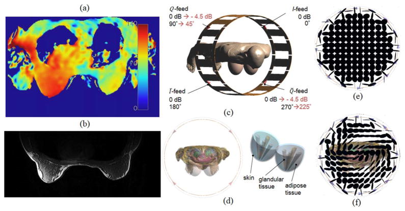
Even at moderately high field strengths such as 3T, inhomogeneity effects are observed and are severe enough in certain applications to warrant detailed understanding and correction—this is especially important at 3T given the clinical importance of this field strength (3). In the case of 3T breast MR, this nonuniformity results in a distinct left–right asymmetry, such that the field magnitude in the left breast is increased by a factor of approximately 1.3 with regard to the right breast for various patient orientations and types of body coils (2–5). An example of the distribution is shown in Figure 1a, with another example in Figure 1b showcasing the MR image shading that results from such an inhomogeneous distribution.
Figure 1.
Example for the distribution (flip angle in degrees) (a) and the resulting image shading in the breast at 3T (b), obtained with a body coil. c: Computational model of a 3T body coil with body model (Virtual Family, Ella, 26 years, IT’IS foundation). d: Additional mammary tissue used for this modeling study. Polarization of the B1-field for unloaded body coil (e) and body coil loaded with body model (f).
Recent research efforts have led to several techniques aimed at reducing nonuniformity for various anatomies; the most recent and theoretically most versatile methods being Transmit SENSE (6,7) and multi-channel RF shimming (8). These methods currently receive considerable attention and are eventually expected to provide ultimate control over transmit field uniformity and safety for future high-field imaging; however, they are also complex methods that require costly additional hardware and considerable computational effort to calculate the optimized excitation parameters.
The work presented here instead focuses on two simple methods without the need for subject-specific optimization, which are moreover readily implementable on today’s clinical systems without significant additional hardware or training effort. The first method is a cost-efficient passive shimming approach, whereby dielectric materials are inserted in the vicinity of the breast to perturb the field lines toward a uniform distribution within the region of interest (ROI). The second method presented is two-channel RF shimming, nowadays readily implemented on several scanners that provide a range of amplitude and phase adjustment possibilities.
The ability to alter the RF field distribution by means of dielectric coil loading was first observed by Foo et al (9); this concept has subsequently been studied by several authors (10–17) in the form of dielectric shimming, with the most extensive analyses by Yang et al (10–12) and Webb et al (13–15). The investigated anatomies were mostly limited to the brain, however, with a small number of publications focused on abdominal, cardiac, and pelvic imaging. Moreover, the available literature is limited to empirical tests of dielectric materials in the vicinity of the body and/or phantoms; while there are only limited modeling and parametric studies available. Therefore, this study aims at the modeling of the effect for the case of 3T breast MR in particular—especially in view of the fact that the presented passive shimming method is simple and low-cost, permits moderate field correction, and is directly usable in clinical settings. In addition, dielectric pads increase the signal locally and, therefore, ultimately provide an increase of SNR and in turn image contrast (11). Moreover, we study the combination of two-channel RF shimming and dielectric shimming to understand the performance benefits of combining these two most widely available and practical shimming methods. The study also studies the safety aspects of our proposed shimming methods to ensure that SAR is maintained within regulatory limits.
MATERIALS AND METHODS
The aforementioned problems of nonuniformity arise as a result of loading of the body coil (Fig. 1c) by the human body. As shown in Figure 1f, the polarization distribution of the B1 field becomes severely perturbed compared with the circularly polarized unloaded B1 field in Figure 1e, even at the moderate field strength of 3T as shown here. This results in a generally noncircular (elliptical) polarization, with certain regions that even degenerate into a linear polarization. In practice, this translates into a smaller left-hand rotating component of the transmitted -field, with the remaining portion of the total B1-field spilling over into the right-hand polarization (i.e., the component of the transmit field), which is not useful for spin excitation—the result is a lower efficiency for spin excitation as well as a decreased receive RF signal in certain areas of the image, leading to local image shading.
The complete optimization of RF or dielectric shimming is a nontrivial task due to the mutual coupling of electric and magnetic fields. It can be described with significant theoretical effort, which is beyond the scope of this manuscript.
Modeling
A quasistatic analysis according to the Biot-Savart law will not be sufficient for the purpose of modeling; dielectric material only acts on the E-field and thus only secondarily on the B-field by coupling, hence no effect would be seen in such a quasistatic analysis. All shimming concepts (both dielectric and RF) were, therefore, investigated using full-wave analysis.
For all simulations, the commercial FDTD software package SEMCAD X (SPEAG, Zürich, Switzerland) was used together with a model of the Virtual Family (Ella, IT’IS foundation, Zürich, Switzerland). In view of the focus on the field distribution in the breast, additional mammary tissue was added specifically to the model as shown in Figure 1d. The electric properties of the added breast tissue at 128 MHz were εr = 5.64, σ = 0.03 S/m (adipose tissue), εr = 65.44, σ = 0.52 S/m (skin), εr = 40, σ = 1 S/m (glandular tissue) (5,18–21). The breast size was chosen to be large to account for the worst-case loading scenario.
The coil was modeled as a shielded 16-leg highpass birdcage coil using the SEMCAD-included birdcage tool, with dimensions selected to approximate the body RF coil on a typical widebore 3T scanner (primary diameter =72 cm, length = 59 cm, shield diameter = 75 cm, length =62 cm). The coil was tuned and matched at 128 MHz loaded with the Ella body model, and a value for S11 below −15 dB was achieved for both I and Q channels.
The simulation study was first conducted without any shimming to confirm the left–right asymmetry effect observed in practice in 3T breast MR images. Subsequently, simulations at different values for the Q-I-amplitude ratio and over a range of Q-I phase differences were carried out, followed by a simulation of the dielectric shimming effect. For the latter, pads of 2 cm thickness were placed in direct contact with the skin on both breasts of the modified Ella model. The breast with the lower value was surrounded by a dielectric pad to increase the field. The simulations were then carried out over different permittivity values for these pads, including the elimination of one pad or the other. In a third step, dielectric and RF shimming were both applied, to form a combined passive-active shimming technique.
For each of the shimming scenarios, maps normalized to the total input power, gain, left–right ratios, and intra-breast variabilities were extracted. The left–right ratio was obtained as the ratio of mean values for in left and right breast. The gain was calculated as the ratio of the mean value of , normalized to the total input power, throughout both breasts and the mean value of for the original circular polarization (quadrature configuration, top left corner, normalized to the square root of the quadrature total input power).
| [1] |
The intra-breast variabilities were calculated as the standard deviation of in each breast in percent. This value is of interest in an effort to monitor and maintain a reasonable intra-breast variability within each breast while trying to reduce left–right asymmetry.
A simulation study on the effects of these two methods on 10g-averaged local SAR was also conducted to analyze the MR safety aspects of the proposed methods. SAR values were normalized to 1 W input power at each port.
In Vivo MR Study
Experimental verification of the simulations was carried out by imaging a population of six female volunteers of average age 30 years (age range, 24–35 years), using a GE Discovery MR750w widebore 3T scanner that had Q-I phase/amplitude shimming capability. The average height and weight were 170.2 cm and 62.7 kg, with an average cup size between B and C. In this scanner model, the amplitude of the Q-port can be adjusted relative to the I-port amplitude from 0 dB down as low as −4.5 dB, and the Q-I phase difference can be adjusted from 90 degrees (quadrature drive; circular polarization) down as low as 45 degrees. The body coil thus served as the transmit coil, with a Sentinelle SPEEDER eight-channel breast array for reception. The dielectric shimming tests were carried out using a commercial dielectric pad from GE Healthcare, of thickness 2 cm. Two flat pad sizes were used, a smaller sized pad measuring 41 × 12 cm2 used in patients with smaller breast sizes, and a larger pad of size 44 × 32 cm2 for larger breast sizes. The dielectric pad was loosely attached to the breast coil and depressions were created by pushing the pad into the coil cavity. The setup presented no discomfort to the patient.
maps were obtained using the Bloch-Siegert method (22,23) with a two-dimensional gradient-echo readout, using a TR of 50 ms, and a scan time of 50 s for a single slice readout. We used an adiabatic Bloch-Siegert (ABS) pulse of 7.6 μT amplitude and 6 ms duration. The excitation flip angle was set to 30 degrees which approximated the Ernst angle for mainly adipose tissue. The resolution of the map was set to 8 mm isotropic. The average global SAR was measured to be 0.4 W/kg during these exams. The obtained maps were normalized to the total input power.
All study procedures were approved by the Stanford Institutional Review Board and informed consent was obtained from all study participants.
RESULTS
Simulation
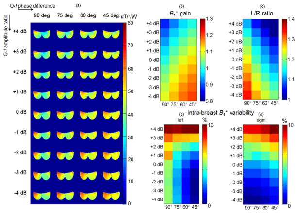
A first simulation of the body+breast model was carried out to confirm the suspected phenomenon of left–right asymmetry. The result is shown in Figure 2a for the quadrature configuration (0 dB Q-I amplitude ratio, 90 degree Q-I phase difference). A left–right asymmetry ratio of approximately 1.24 was obtained, which is a reasonable match to the measured asymmetry ratio of 1.32 (3). The left–right asymmetry ratio was also calculated for the original Ella body model without added mammary tissue, and a ratio of 1.26 was obtained. The relatively low variation of the left–right ratio with different breast sizes is likely due to the high fat content of breast tissue (εr = 10). In comparison, other tissue types have higher water content (εr = 80) and, therefore, changes in these anatomies perturb the field stronger than breast tissue. It is concluded from this result that breast size only marginally influences left–right asymmetry ratios.
Figure 2.
RF shimming simulation results: distribution for different shim amplitudes and phases (normalized to the total input power) (a), gain (b), and left–right ratios (c), and intra-breast variabilities in percent in left (d) and right (e) breast.
Figure 2 also shows simulation results obtained for RF shimming alone for a variation of the Q-I amplitude ratio from +4 dB to −4 dB and a variation of the Q-I phase difference from 90 to 45 degrees. Figure 2a shows the maps, whereas b and c show the gain and the left–right ratios for each of the configurations shown in a). The results also show intra-breast variability in Figures 2d and e.
The presented RF shimming results indicate that phase shimming alone resolves a large amount of the asymmetry observed. For example, a decrease of the Q-I-phase difference from 90 to 45 degrees in the simulation reduces the left–right ratio from 1.24 to 1.05. Amplitude variation alone also reduces the asymmetry effect: an increase in Q-I-amplitude ratio from 0 dB to +3 dB improves the left–right asymmetry ratio from 1.24 to 1.13. A decrease in Q-I amplitude ratio instead seems to introduce more asymmetry. Combined amplitude ratio increase (+3 dB) and phase difference decrease (45 degrees) lead to an optimized left–right ratio of 1.00, whereas an amplitude ratio increase of +4 dB together with a phase difference decrease of 45 degrees leads to a reversed left–right ratio of 0.97.
gain also improves with a decrease in Q-I phase difference, by a factor of 1.13 for a 45 degree decrease. An improvement is also found for lower Q-I-amplitude ratios: for a Q-I amplitude ratio of −3 dB and a phase decrease of 45 degrees, a gain of 1.19 is achieved.
The intra-breast variability in the left breast can be decreased by phase-only shimming, using only moderate or no Q-I amplitude shimming, (e.g., from 4.5% to 0.8% with phase-only shimming using a phase difference of 45 degrees), however, larger values for the Q-I amplitude ratio will worsen the effect (for example, Q-I amplitude ratios of +3 dB and +4 dB increase the variability to 6.4% and 15.2%, respectively, with Q-I phase difference set to 45 degrees in both cases. The intra-breast variability in the right breast increases for all shimming settings (2.4% to 3.1% for phase-only shimming (45 degrees), as well as 7.8% and 12% for Q-I amplitude ratios of +3 dB and +4 dB, respectively, both using a Q-I phase difference of 45 degrees.
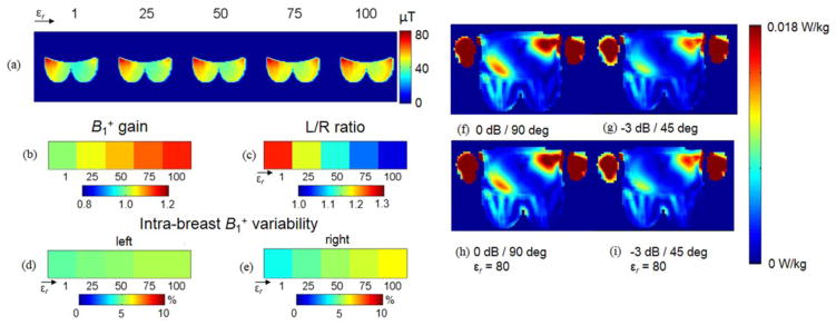
Figure 3 shows a parametric analysis for a dielectric pad on the left breast, with different values for the relative permittivity. Figures 3b and c show the gains and left–right ratios, Figures 3d and e illustrate the intra-breast variability. The results show that a dielectric pad alone of relative permittivity εr = 100 will decrease the left–right ratio from 1.24 to 1.03. As a comparison, if the relative permittivity of the dielectric pad is 80 to better mimic the permittivity of a commercially available dielectric pad, then the simulated left–right ratio is 1.08. Note that the gain is increased by 15% due to the presence of the dielectric pad. The intra-breast variabilities show a slight increase (by 1–2%) for a pad of relative permittivity εr = 100. This is attributed to the fact that the pad only acts on tissue in its vicinity, i.e., around the edge of the breast.
Figure 3.
Dielectric shimming simulation results: distribution for different relative dielectric permittivities (a), gain (b), left–right ratios (c), and intra-breast variabilities in percent in left (d) and right (e) breast. Simulated 10g-averaged local SAR (Normalized to 1W input power at each port) for quadrature drive (f), RF shimming only (g), dielectric shimming only (h), and combined RF and dielectric shimming (i).
Figure 4 shows the simulation results for combined RF and dielectric shimming. In this scenario a dielectric pad of relative permittivity εr = 80 (to best match the permittivity of the commercial pad used in the presented in vivo studies) is placed on the left breast and then simulated for Q-I amplitude ratios from 0 to −4 dB and Q-I phase differences from 90 to 45 degrees. Figures 4b and c show the gains and left–right ratios for the case of combined RF and dielectric shimming, Figures 4d and e show the intra-breast variabilities. A general increase in normalized amplitude can be observed due to the presence of the additional dielectric pad. In terms of left–right ratio, a decrease in Q-I phase difference to 75 degrees alone, together with the dielectric pad of relative permittivity εr = 80 leads to the desired left–right ratio of 1.00, with stronger shimming attempts leading to a reversed left–right ratio. Positive values for the Q-I amplitude ratio are omitted because they mostly lead to a reversed asymmetry.
Figure 4.
RF and dielectric combined shimming simulation results: distribution for different shim amplitudes and phases (normalized to the total input power) (a), gain (b), left–right ratios (c), and intra-breast variabilities in percent in left (d) and right (e) breast. A dielectric pad of permittivity εr = 80 has been used. [Color figure can be viewed in the online issue, which is available at wileyonlinelibrary.com.]
While the field homogeneity can be improved, special attention has to be paid to the effect of the aforementioned perturbations on the local SAR distribution. Theoretically, SAR hotspots that are present in the original unshimmed case can increase or relocate after shimming, and it is, therefore, important to analyze this in detail. Figures 3f–i show the simulated local SAR normalized to the total input power for RF shimming and dielectric shimming separately. The local SAR for the case of RF shimming shows a reduced SAR pattern (Fig. 3g), compared with the quadrature configuration shown in Figure 3f. The use of a dielectric pad does not affect the SAR values in the vicinity of the corresponding breast (Figs. 3h, i). The simulated partial body SAR was calculated to 0.64 W/kg and 0.55 W/kg with and without RF shimming in simulation. Dielectric shimming did not affect these values.
In Vivo
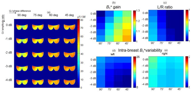
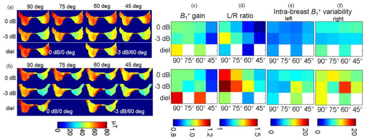
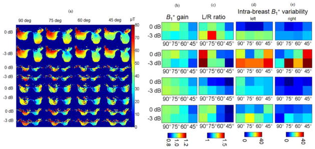
To prove the concept of this technique, maps were acquired experimentally with and without shimming techniques applied. Figure 5 shows RF shimming alone and combined dielectric and RF shimming for two different Q-I phase/amplitude configurations for two different subjects (a,b), together with the gains (c), left–right ratios (d), and intra-breast variability (e and f). Figure 6 shows the results for RF shimming only, in four additional subjects. It is observed that the left–right ratio can be decreased in all subjects by Q-I phase-shimming alone (an average ratio of 1.1 is achieved with a decrease in phase difference of 45 degrees, starting from an average ratio of 1.26 for the unshimmed case). This represents a reduction of 13%, which is in agreement with a reduction of 10% obtained from simulation. Additional improvements would be expected with Q-I amplitude/phase shimming, if the scanner allowed for positive Q-I amplitude ratios. Additional dielectric shimming decreases the left–right ratio compared with RF shimming alone, on average by 6.7% for the commercial pad, which is in agreement for the simulated value of 5.6%. The gain for the presented in vivo plots cannot be directly compared with simulations, as the experimental values are scaled to the maximum amplitude that the system can generate. The intra-breast variabilities increase slightly using both RF (left: +4%, right: +1%; both values for a phase difference decrease of 45 degrees) and dielectric shimming (+2% for the commercial pad), similar to the values observed in simulation. Additional errors are attributed to noise artifacts in the generated -maps. It is noted here that, in some of the experimental cases, shimming adjustments in the form of larger Q-I amplitude ratios and decreased Q-I phase differences may be required to fully mitigate the inhomogeneity effect compared with the simulation; an improvement is, however, seen in all cases with the proposed shimming values. This is mostly due to large variations in patient size and the consequent differences in coil loading, which leads to a more pronounced asymmetry effect for the quadrature configuration.
Figure 5.
In vivo shimming results: distribution in μT for different shim amplitudes and phases for subject 1 (a), subject 2 (b), and the corresponding gains (c), left–right ratios (d), and intra-breast variabilities in percent in left (e) and right (f) breast.
Figure 6.
RF shimming in vivo results: distribution for different shim amplitudes and phases (a), gain (b), left–right ratios (c), and intra-breast variabilities in percent in left (d) and right (e) breast.
DISCUSSION
The results presented above confirm that the observed phenomenon of left–right asymmetry is well predicted by simulation. A previous in vivo study showed a measured left-ratio of 1.32 among a population of 30 patients (3). These previous results coincide with the simulation results and in vivo results presented above.
RF shimming is capable of removing the left–right asymmetry, and is moreover useful in increasing gain. Dielectric shimming has a confirmed positive effect as well. Optimum settings for gain. can be achieved with lower values of Q-I amplitude ratios, which increases gain. Therefore, we conclude that either RF or dielectric shimming alone will yield positive results, but that an even greater effect is achieved if both are used together. This finding might have practical implications for situations where the RF shimming capability of the scanner is constrained.
The GE MR 750w model used in this study only allows for a decrease in Q-I amplitude ratio and phase difference (0 to −4.5 dB and 90 to 45 degrees, respectively); however, following the aforementioned results, adjustment of the phase difference alone is still quite effective in improving the left–right asymmetry. Further improvements in terms of homogeneity and efficiency in breast imaging may require a wider range of adjustment on both Q-I phase difference and (especially) Q-I amplitude ratio.
It is to be noted that this two-channel RF shimming technique differs from the more complex RF shimming techniques by its readily available implementation on commercial systems that allow for independent adjustment of the I and Q channels of the transmit body coil. This is in contrast to multi-channel RF shimming, which is applicable to any coil type, including surface arrays, requiring a highly complex computational optimization effort. With the technique described in this study, a general setting for the Q-I amplitude ratio and phase difference can be found that is expected to lead to improved left–right ratio in the average patient. An optimized setting to be used on GE scanners is, therefore, proposed as a Q-I amplitude ratio and phase difference of 0 dB and 45 degrees, respectively. With additional dielectric pads, asymmetry can be reached with lower values for the Q-I phase difference and gain can be increased further.
The attentive reader will also note that it might be better to use two different dielectric materials, one with higher dielectric permittivity on the left breast, together with a second pad of lower permittivity on the right breast, with the goal of increasing gain. In this regard, recent research has been demonstrating ever higher values for the dielectric permittivity (24), and several studies have been conducted on the MR specific optimization of such dielectric materials in terms of their T1 and T2 relaxation parameters to ensure low background signal in an MR scan (16). A future study could, therefore, expand on this analysis using dielectric pads of higher permittivity and optimized relaxation characteristics. It is also interesting to note that an optimized configuration must exist for the material, placement, and geometry of such pads. This is beyond the scope of this study but might improve the performance achieved here, especially in terms of intra-breast variability, and might be a subject for investigation in the future.
Regarding safety aspects, the results for SAR are in agreement with (15) for dielectric shimming. While SAR has to be predicted and monitored when using RF shimming, dielectric pads commonly reduce SAR (13), and can, therefore, be used to supplement moderate RF shimming, as a strategy for staying within SAR guidelines when needed.
Altogether, it can be concluded that compared with more complex methods such as Transmit SENSE and RF shimming using more than two channels, the techniques outlined in this study offer a simple and practical method that can be implemented without the need for expensive additional hardware or changes in the scanner configuration. The methodologies described here can be used when needed during a scan without any additional requirements (most commercial systems now include the additional Q-I amplitude/phase adjustment) for advanced operator training or scanner upgrades.
The limitations of the proposed technique lie in the fact that only a standard set of values for Q-I amplitude/phase adjustment can be selected. The radiologist or MR technician can select different phases and amplitudes upon inspection of a first image and then fine tune this selection, as well as exchange the dielectric pad for a different material or size. However, there is no automation or optimization included in this approach, which is done in favor of simplicity of the proposed method.
In conclusion, two shimming modalities to reduce left–right asymmetry in 3T breast MR are proposed, the first using passive dielectric insert elements, and the second using a two-channel RF shimming approach. Both methods are readily implementable on many modern systems and represent a simple, practical, and inexpensive alternative to more complex Transmit SENSE and multi-channel RF shimming alternatives. With appropriate tuning of shimming parameters, the methods successfully restore uniformity and hence uniform image contrast while at the same time increasing gain; for this reason these shimming methods are expected to improve breast cancer detection and diagnosis by 3T MRI.
Acknowledgments
Contract grant sponsor: NSERC Canada; Contract grant sponsor: GE Healthcare; Contract grant sponsor: NIH; Contract grant number: P41 EB015891; Contract grant sponsor: the Lucas Foundation.
The authors acknowledge research support from NSERC Canada, GE Healthcare, NIH, and the Lucas Foundation, as well as the invaluable assistance of Mohammad Mehdi Khalighi, Mihir Rajendra Pendse, Kevin and Karla Epperson, and all volunteers in the preparation of this manuscript.
References
- 1.Gati JS, Menon RS, Ugurbil K, Rutt BK. Experimental determination of the BOLD field strength dependence in vessels and tissue. Magn Reson Med. 1997;38:296–302. doi: 10.1002/mrm.1910380220. [DOI] [PubMed] [Google Scholar]
- 2.Kuhl CK, Kooijman H, Gieseke J, Schild HH. Effect of B1 inhomogeneity on breast MR imaging at 3.0 T. Radiology. 2007;244:929–930. doi: 10.1148/radiol.2443070266. [DOI] [PubMed] [Google Scholar]
- 3.Rakow-Penner R, Hargreaves BA, Glover G, Daniel BL. Breast MRI at 3T. Appl Radiol. 2009;38:6–13. [Google Scholar]
- 4.Sung K, Daniel BL, Hargreaves BA. Transmit B1+ field inhomogeneity and T1 estimation errors in breast DCE-MRI at 3 tesla. J Magn Reson Imaging. 2013;38:454–459. doi: 10.1002/jmri.23996. [DOI] [PMC free article] [PubMed] [Google Scholar]
- 5.Winkler SA, Rutt BK. Practical methods for improved B1+-homogeneity in 3T breast imaging. Proceedings of the 21st Annual Meeting of ISMRM; Salt Lake City. 2012; p. abstract 397. [Google Scholar]
- 6.Katscher U, Bornert P, Leussler C, van den Brink JS. Transmit SENSE. Magn Reson Med. 2003;49:144–150. doi: 10.1002/mrm.10353. [DOI] [PubMed] [Google Scholar]
- 7.Zhu Y. Parallel excitation with an array of transmit coils. Magn Reson Med. 2004;51:775–784. doi: 10.1002/mrm.20011. [DOI] [PubMed] [Google Scholar]
- 8.Ibrahim TS, Lee R, Baertlein BA, Abduljalil AM, Zhu H, Robitaille PM. Effect of RF coil excitation on field inhomogeneity at ultra high fields: a field optimized TEM resonator. Magn Reson Imaging. 2001;19:1339–1347. doi: 10.1016/s0730-725x(01)00404-0. [DOI] [PubMed] [Google Scholar]
- 9.Foo TK, Hayes CE, Kang YW. Reduction of RF penetration effects in high field imaging. Magn Reson Med. 1992;23:287–301. doi: 10.1002/mrm.1910230209. [DOI] [PubMed] [Google Scholar]
- 10.Yang QX. Method of utilization of High Dielectric Constant (HDC) materials for reducing SAR and enhancing SNR in MRI. 20110152670. US patent. 2011 Jun 23;
- 11.Yang QX, Mao W, Wang J, et al. Manipulation of image intensity distribution at 7.0 T: passive RF shimming and focusing with dielectric materials. J Magn Reson Imaging. 2006;24:197–202. doi: 10.1002/jmri.20603. [DOI] [PubMed] [Google Scholar]
- 12.Yang QX, Wang J, Zhang X, et al. Analysis of wave behavior in lossy dielectric samples at high field. Magn Reson Med. 2002;47:982–989. doi: 10.1002/mrm.10137. [DOI] [PubMed] [Google Scholar]
- 13.Brink WM, Webb AG. High permittivity pads reduce specific absorption rate, improve B homogeneity, and increase contrast-to-noise ratio for functional cardiac MRI at 3 T. Magn Reson Med. 2014;71 doi: 10.1002/mrm.24778. spcone. [DOI] [PubMed] [Google Scholar]
- 14.de Heer P, Brink WM, Kooij BJ, Webb AG. Increasing signal homogeneity and image quality in abdominal imaging at 3 T with very high permittivity materials. Magn Reson Med. 2012;68:1317–1324. doi: 10.1002/mrm.24438. [DOI] [PubMed] [Google Scholar]
- 15.Teeuwisse WM, Brink WM, Haines KN, Webb AG. Simulations of high permittivity materials for 7 T neuroimaging and evaluation of a new barium titanate-based dielectric. Magn Reson Med. 2012;67:912–918. doi: 10.1002/mrm.24176. [DOI] [PubMed] [Google Scholar]
- 16.Haines K, Smith NB, Webb AG. New high dielectric constant materials for tailoring the B1+ distribution at high magnetic fields. J Magn Reson. 2010;203:323–327. doi: 10.1016/j.jmr.2010.01.003. [DOI] [PubMed] [Google Scholar]
- 17.Jackson JD. Classical electrodynamics. New York: Wiley; 1999. p. xxi.p. 808. [Google Scholar]
- 18.Lazebnik M, Popovic D, McCartney L, et al. A large-scale study of the ultrawideband microwave dielectric properties of normal, benign and malignant breast tissues obtained from cancer surgeries. Phys Med Biol. 2007;52:6093–6115. doi: 10.1088/0031-9155/52/20/002. [DOI] [PubMed] [Google Scholar]
- 19.Porter E, Fakhoury J, Oprisor R, Coates M, Popovic M. Improved tissue phantoms for experimental validation of microwave breast cancer detection. Proceedings of the Fourth European Conference on Antennas and Propagation (EuCAP); Barcelona. 2010; pp. 1–5. [Google Scholar]
- 20.Porter E, Santorelli A, Bourdon A, Coulibaly D, Coates M, Popovic M. Time-domain microwave breast cancer detection: experiments with comprehensive glandular phantoms. Proceedings of the Microwave Conference (APMC), Asia-Pacific; Melbourne. 2011; pp. 203–206. [Google Scholar]
- 21.Winkler SA, Porter E, Santorelli A, Coates M, Popovic M. Recent progress in ultra-wideband microwave breast cancer detection. Proceedings of the IEEE International Conference on Ultra-Wideband (ICUWB); Syracuse. 2012; pp. 182–186. [Google Scholar]
- 22.Khalighi MM, Rutt BK, Kerr AB. Adiabatic RF pulse design for Bloch-Siegert B 1+ mapping. Magn Reson Med. 2012;70:829–835. doi: 10.1002/mrm.24507. [DOI] [PMC free article] [PubMed] [Google Scholar]
- 23.Sacolick LI, Wiesinger F, Hancu I, Vogel MW. B1 mapping by Bloch-Siegert shift. Magn Reson Med. 2010;63:1315–1322. doi: 10.1002/mrm.22357. [DOI] [PMC free article] [PubMed] [Google Scholar]
- 24.Rupprecht S, Sica CT, Raffi S, Seongtae K, Lanagan MT, Yang QX. Drastic enhancement and manipulation of RF field with Ultra High Dielectric Constant (uHDC) material at 3T. Proceedings of the 21st Annual Meeting of ISMRM; Salt Lake City. 2013; p. abstract 396. [Google Scholar]


