Abstract
In retinal microsurgery, membrane peeling is a standard procedure requiring the delamination of a thin fibrous membrane adherent to the retina surface by applying very small forces. Robotic devices with combined force-sensing instruments have significant potential to assist this procedure by facilitating membrane delamination through induced micro-vibrations. However, defining the optimal frequency and amplitude for generating such vibrations, and updating these parameters during the procedure is not trivial. Automatic adjustment of these parameters via an adaptive control scheme is possible only if the individual parameter effects on delamination behavior are known. This study presents an experimental exploration of how micro-vibration amplitude and frequency affect membrane peeling forces alone. Combining a micromanipulator and a force-sensing micro-forceps, several peeling experiments were done on artificial phantoms (bandages) and inner shell membrane of raw chicken eggs. In the tested range of micro-vibration frequencies (10-50 Hz) the average delamination force was minimized mostly at 30 Hz for the bandages and at 50 Hz for the egg membranes. Increasing the micro-vibration amplitude from 50 μm up to 150 μm provided further reduction in average force, thus facilitated membrane delamination.
I. Introduction
In retinal microsurgery, surgeons manipulate extremely delicate tissues by applying very small forces that are routinely below the human tactile sensation threshold. A prototypical vitreoretinal task is membrane peeling, where the surgeon delaminates a very thin fibrous membrane (micron scale) adherent to the retinal surface, using either a pick or micro-forceps. Successful execution of this task requires extensive experience, and is extremely difficult to master due to suboptimal visualization, inconsistent tissue properties, surgeon's physiological hand tremor, fatigue and involuntary patient motion. During the critical steps in the operation, the instruments need to be moved very slowly, within a range of 0.1-0.5 mm/s, in an extremely delicate environment, to minimize deleterious force transfer to tissue. Furthermore, the required forces for delamination routinely lie below the surgeon's sensory threshold. These forces were shown to be below 7.5 mN in porcine cadaver eyes and only 19% of events with this force magnitude could be felt by surgeons [1]. Application of forces beyond this level can damage retinal veins [2] and give rise to serious complications such as iatrogenic retinal injury and breaks [3], vitreous hemorrhage, or subretinal hemorrhage [4] leading to potentially irreversible damage and loss of vision.
Membrane peeling is essentially a two-phase procedure [5]. In the first phase, the surgeon approaches the membrane, precisely grasps and then lifts it to create a surgical edge and plane. Tool visualization, positioning accuracy and tremor suppression are important during this step. For assisting this phase, several teleoperated [6-9], cooperatively controlled [10], and handheld [11-15] robots were developed. Among the handheld devices is Micron, an actively stabilized micromanipulator developed by Riviere et al. at Carnegie Mellon University [11]. It uses optical tracking and piezoelectric actuators for deflecting the tool tip. Micron was shown to suppress tremor effectively, but it still has unexplored potential utility especially for the second phase of this clinical procedure, which is the actual delamination of the grasped pathological membrane. During this phase, the main concern is limiting the forces exerted on the retina more so than simply canceling tremor. This requires the development of (1) smart instruments that accurately measure the exerted forces, and (2) methods to reduce and maintain these forces at a safe level.
In order to measure the exerted forces inside of the eye, a family of force-sensing instruments was developed at Johns Hopkins University using fiber Bragg grating (FBG) strain sensors. These tools are able to capture the forces at the tool tip without any adverse effect from tool-to-sclera interaction. First, a single degree of freedom (DOF) force-sensing tool [16] and then a 2-DOF pick-like instrument [17-19] were built. Intuitively, compared with a pick tool, the forceps provide more controlled manipulation of the tissue by firmly grasping it. This enables easier removal of the membrane from the eye in a single step [20]. With this motivation, tool development continued with a manual pair of 2-DOF force-sensing forceps [21], followed by a 2-DOF forceps that can be used with the Steady-Hand Robot [23]. We recently presented a 2-DOF force-sensing micro-forceps for Micron. This design was shown to be sufficiently compact and lightweight for Micron to operate properly, and the benefits of the resulting device was demonstrated on artificial bandage phantoms [23, 24].
In simulated ophthalmic procedures, auditory force feedback was shown to help in maintaining the exerted forces below potentially dangerous levels [19, 25]. In addition, there are motivating applications in other fields that may help in reducing forces, such as inserting a biopsy needle, where reciprocation of the needle was shown to facilitate the advance of the needle through tissue and penetration of the site of interest [26]. Recently, we have shown that inducing micro-vibrations on the tool tip can facilitate delamination of membranes as well [24]. However, deciding on the optimal frequency and amplitude of these vibrations during the surgical operation, and updating this information based on exerted forces in real time is not trivial.
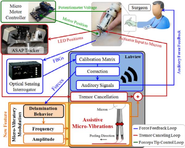
This study builds on our previous work [24], explores the effect of the main micro-vibration parameters on membrane peeling forces, and aims to establish an adaptive control algorithm (Fig. 1) for regulating micro-vibrations during the procedure. In the following sections, we will first present the force-sensing micro-forceps system. This will be followed by the experimental investigation of micro-vibrations during membrane peeling on two types of phantoms: artificial bandages and raw chicken eggs.
Figure 1.
System overview. A handheld micromanipulator (Micron) was combined with a force-sensing micro-forceps to assist membrane peeling previously [23]. A novel feature, vibrating the tool tip along the peeling direction, is added to the system to facilitate membrane delamination (shown in orange).
II. System Components
A. The Micromanipulator
In order to suppress involuntary hand motion, and induce assistive micro-vibrations during membrane peeling, our system uses a handheld micromanipulator: Micron [11]. This device is normally designed to cancel the physiological hand tremor of the surgeon. The position of its handle is determined by its custom microscale optical tracking system, namely the ASAP (Apparatus to Sense Accuracy of Position). After sensing the tool motion, it is filtered into its voluntary and involuntary (tremulous) components [11]. Then activating its 3 piezoelectric actuators, Micron moves its tip to counteract the involuntary motion component within a workspace of approximately a 1×1×0.5 mm volume centered on the handle position. The control software for this operation mode was already implemented in LabVIEW. For our system, we extended the existing control loop by adding controlled pulses onto the filtered (non-tremulous) tool tip trajectory with variable frequency and amplitude (Fig. 1). In order to identify the individual effect of frequency and amplitude on delamination forces, these variables are currently set manually. But the ultimate aim is to develop an adaptive control law—based upon the delamination response to each parameter—that will tune the frequency and amplitude automatically according to measured tool-to-tissue forces.
B. The Micro-Forceps Module
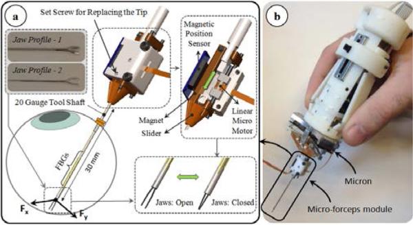
For accurate manipulation of the tissue, a firm grasping mechanism is necessary. In our previous work, we developed a motorized force-sensing micro-forceps module that fits onto Micron without interfering with its operation [24]. The unit is a “drop-in” module carrying all the necessary actuators and sensors (Fig. 2). The actuation is provided by a linear micro motor (Squiggle-RV-1.8 by New Scale Technologies Inc., Victor, NY), which slides the tubular tool shaft up and down along the tool axis to respectively open and close the forceps jaws. The forceps jaws are fixed to the module body via a set screw, and can easily be replaced. This enables the use of various jaw profiles for handling various surgical tasks, such as the thicker profile-1 in Fig. 2a for peeling dense epiretinal membranes and the slimmer profile-2 for delamination of finer internal limiting membranes. In addition, since the forceps jaws can wear and deform with use, easy jaw replacement enables use in prolonged or repeated tests without deterioration of the grasping quality.
Figure 2.
(a) The motorized force-sensing micro-forceps module [24]. The tool provides firm grasping functionality, can accommodate various jaw profiles for handling different types of tissues (profile-1 for thick epiretinal membranes, and profile-2 for internal limiting membranes), and senses the transverse forces exerted at its tip via the embdedded FBGs. (b) The micro-forceps module is compatible with the handheld micromanipulator, Micron.
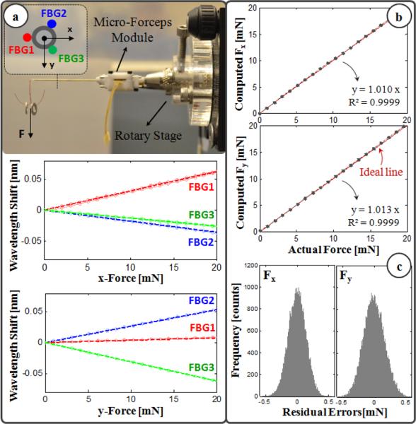
The micro-forceps module is capable of sensing the transverse forces exerted at its tip via the 3 FBG strain sensors attached evenly around the tool shaft. The calibration setup and protocol of the force sensor follow [17]. The wavelength shift in each FBG sensor normally depends linearly on both the local strain and the temperature variation. During calibration, the effect of temperature change was removed by subtracting the mean wavelength shift from each sensor measurement. Resulting temperature-compensated sensor readings exhibit a linear reproducible behavior during both the x- and y-axis calibration procedures, as shown in Fig. 3a. The slopes of the response curves form the calibration matrix (K). The Moore-Penrose pseudo-inverse of this matrix (K+) is used in the linear relationship (1) to compute the transverse tool tip forces (Fx and Fy) from FBG wavelength shifts (ΔS) during the operation.
| (1) |
Figure 3.
(a) Calibration results: linear response for all FBGs when the tip is loaded along x and y axes. (b) Computed forces versus the actual forces along x and y axes. (c) The histogram of the residual errors.
In order to monitor the FBGs, we use an optical sensing interrogator (sm130-700 from Micron Optics Inc., Atlanta, GA). The wavelength resolution of the interrogator is 1 pm. Based upon the obtained calibration matrix, this corresponds to a transverse force resolution of about 0.21 mN. To verify sensor operation, the tool tip was loaded and unloaded repeatedly in different angles (0°, 45° and 90°), and the computed forces were compared with the actual tip loading. Results showed consistency with the actual values for both Fx and Fy, and a close fit to the ideal straight line (slope=1) passing through the origin (Fig. 3b). The root mean square error was 0.14 mN and 0.17 mN respectively for Fx and Fy. The histogram of the residual errors in Fig. 3c show that the probability of errors beyond 0.5 mN is very low.
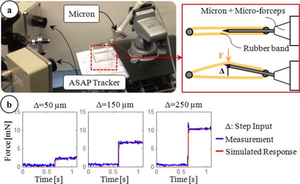
Accurate measurement of membrane peeling forces in the presence of micro-vibrations requires not only sub-mN force-sensing resolution but also a very fast responding force sensor. The transient response of the force-sensing tip was monitored using the setup shown in Fig. 4a. First, the micro-forceps module was mounted onto Micron, and the forceps tip was held between two elastic rubber bands. Then, Micron was given a step input to move the tool tip towards one side laterally while the resulting reaction force was recorded. The tests were repeated for 3 levels of step amplitude (50, 150 and 250 μm). In all case, the measured force profile matched a first order system response with 0.005 s time constant as shown in Fig. 4b, proving a fast enough response to track rapid force variations even in the presence of high frequency micro-vibrations (in our case up to 50 Hz).
Figure 4.
Transient response characteristics of the force sensor: (a) setup, (b) step response of the sensor. Simulated response of a first order system with a time constant of 0.005 seconds matched the measured force profile.
III. Experiments
A. Setup
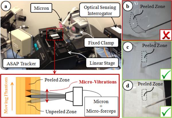
There are various factors affecting the forces in membrane peeling. Some of these pertain to tissue properties, such as tissue width and thickness, while some are related to the motion of the peeling instrument, such as the peeling speed. In order to isolate the influence of micro-vibrations, all other factors affecting the peeling force need to be eliminated in a very reproducible experimental setup. Using a handheld micromanipulator, it is hard to keep the peeling speed constant. To avoid peeling speed alterations during and between trials, we fixed the Micron handle to a clamp, and used a linear stage to drive phantoms relative to Micron (Fig. 5). The micro-forceps module was attached onto Micron for grasping the phantom before peeling. This setup is only for identifying the effect of microvibrations in membrane delamination. The practical use of our system will work based on this identified behavior, but will be handheld (not with a linear stage) as shown in Figs 1 and 2.
Figure 5.
Experimental setup: (a) To ensure constant peeling speed, the phantoms were moved on a linear stage. (b) Peeling inner shell membrane of raw eggs produces triangular shaped strips, and requires both tearing and delaminating forces. Using sliced egg shell membranes (c) and bandages (d), the effect of tearing forces and varying membrane width throughout delamination were avoided.
To simulate epiretinal membrane, inner shell membrane (ISM) of raw chicken eggs can normally be used. However, in this phantom, the membrane routinely comes off the egg shell creating a non-uniform triangular piece of membrane if a linear peeling trajectory is followed (Fig. 5b). The varying width of the peeled tissue significantly affects the forces, and the dimensions of this wedge shape varies between the phantoms. To peel consistent and constant width membrane strips, a helical trajectory needs to be followed as in [29]. However, such dexterous motion is not possible using a linear stage. Furthermore, while peeling the ISM, the measured forces stem from two main sources: (1) the tearing force between the peeled section and the surrounding membrane; (2) the delaminating force due to the adhesion between the peeled section and the underlying shell. Of these components—for purposes of epiretinal and/or internal limiting membrane peeling—we believe the delaminating force is more critical, and needs to be reduced/limited as it is the force that is directly applied onto the delicate retinal surface. In order (1) to eliminate the tearing forces and focus purely on the delaminating forces, and (2) to fix the width of the peeled layers for consistency between trials, we used two different phantoms: sliced bandages and sliced shell membranes of raw chicken eggs.
The bandage phantom was prepared by slicing sticky tabs from 19 mm Clear Bandages (Rite Aid Corp.) into 2 mm wide strips (Fig. 5d). Repeated peeling tests using a single bandage strip on the setup shown in Fig. 5a revealed that the adhesion between the bandage strip and its backing decays with each peel initially (Fig. 6). However, after approximately the 10th peel, the bandage sticks back on consistently, requiring similar amount of delamination force for a prolonged time. This enables the use of each strip numerous times by brushing it back in place with its consistent level of adhesion after each peel, and provides a very repeatable platform for conducting multiple tests.
Figure 6.
A single bandage strip was peeled at constant speed (0.15 mm/s) and brushed back on several times. The required delamination force leveled off after approximately the 10th peel.
The membrane inside the raw chicken egg shell was sliced similarly using a razor (Fig. 5c). Both the inner and the adherent outer shell membranes are cut together. Thus, while peeling the cut strips, both membranes need to be delaminated off the egg shell surface, which requires a larger force as compared to the removal of ISM alone. In contrast to the bandage phantom, each membrane strip can be used only once, limiting the total number of tests on this phantom. Yet, assuming that the membrane structure does not vary significantly between the eggs, this phantom provides a consistent platform for studying the effect of micro-vibrations on peeling biological tissue.
B. Procedure
Peeling tests on the bandage phantom were done in 2 sets, each set having a different speed setting (0.15 mm/s and 0.3 mm/s). In each set, a total of 10 operational modes were examined. In the first mode, delaminating forces during regular peeling were monitored. The remaining modes explored the effect of micro-vibrations at 3 frequencies (10, 30 and 50 Hz) and 3 amplitudes (50, 100 and 150 μm). 15 trials per mode were completed using a single bandage strip for each speed setting. Each bandage was peeled and brushed back 10 times before starting the trials, so that the adhesion between the bandage and its backing remained consistent throughout the experiments (Fig. 6). For the egg trials, the experimental conditions were limited to 1 speed setting (0.15 mm/s), 2 frequencies (30 and 50 Hz) and 2 amplitudes (100 and 150 μm). Ten shell membrane strips were peeled for each setting, and each strip was used only once.
The experiments were conducted by alternating the order of experimental modes. Each strip was peeled continuously for a 60 second period. The measured tool tip force was acquired at 1 kHz. The average and maximum peeling force (Faverage and Fpeak) for each mode were analyzed using oneway analysis of variance (ANOVA) followed by a t-test assuming unequal variance. Statistical significance was defined as p<0.05.
IV. Results and Discussion
A. Frequency of Micro-Vibrations
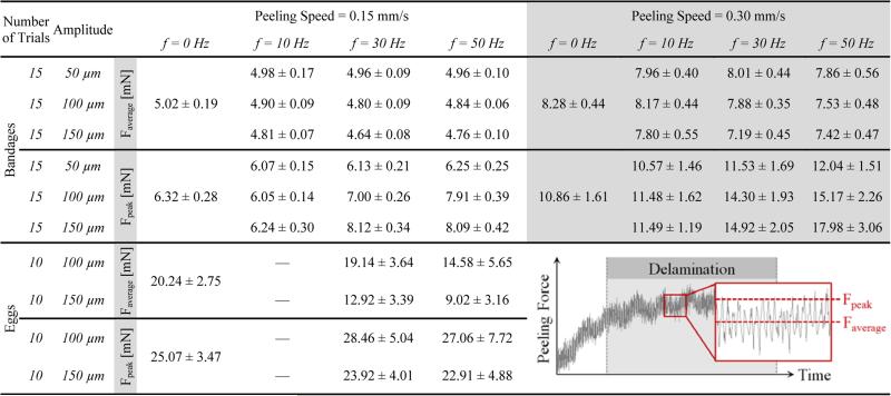
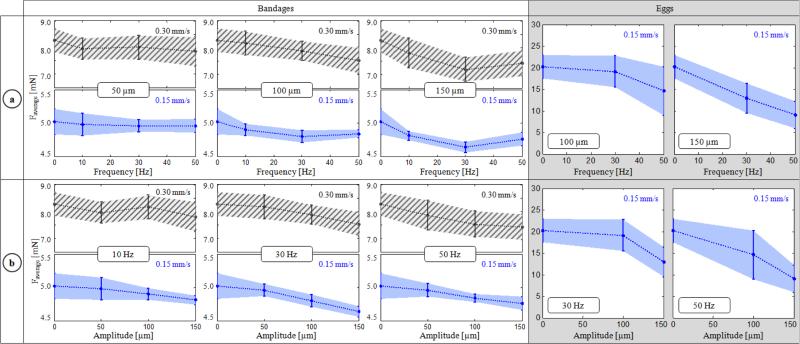
The variation of delaminating forces with respect to micro-vibration frequency is shown in Table I and Fig. 7a for both phantoms. For Faverage, no statistically significant difference was identified between the different frequency settings with a 50 μm amplitude (p=0.62). Faverage remained around 5mN and 8 mN respectively for 0.15 mm/s and 0.30 mm/s speed settings regardless of the induced micro-vibrations. However, at larger amplitudes (100 and 150 μm), the change in force was significant. In the slower speed setting, Faverage was minimized at 30 Hz to 4.80 mN and 4.64 mN respectively for 100 μm and 150 μm vibrations (p<0.05). Doubling the speed changed this profile to a monotonically decreasing curve for 100 μm vibrations, but a similar concave trend with a minimum (7.19 mN) at 30 Hz appeared for 150 μm vibrations (p<0.05). Faverage for shell membranes (20.2 mN) was much larger as compared to bandages (5.02 mN). Introducing micro-vibrations with increasing frequency gradually decreased this force, down to 9.02 mN at 50 Hz. The drop was statistically significant for all settings (p<0.05) except for 30 Hz vibrations at 100 μm (p=0.24). The change in Faverage combined with the amplitude of force fluctuations due to induced vibrations affected Fpeak as well. Peeling bandages with 10 Hz vibrations resulted in a reduced Fpeak for the slower speed setting. Though for the faster peeling case, only 10 Hz and 50 μm vibrations produced this result. In most cases—excluding the slower peeling tests with 150 μm vibrations—Fpeak gradually rose as the frequency was increased (p<0.05).
Table I.
Mean and Standard Deviation of the Measured Average and Peak Peeling Force for Each Micro-Vibration Setting
Figure 7.
Variation of average peeling force (Faverage) with respect to the (a) frequency and (b) amplitude of micro-vibrations. Dotted lines represent the mean, and the shaded region is ±1 standard deviation. Inducing micro-vibrations at an “optimal” frequency among the tested cases—at 30 Hz for bandages, and at 50 Hz for the egg shell membranes within the tested frequency interval—minimized Faverage. The force-frequency trend varied depending upon the peeling speed (0.15 mm/s in blue vs. 0.30 mm/s in striped grey) as seen from bandage peeling with 100 μm vibrations. Increasing the amplitude of micro-vibrations lowered Faverage in most cases, except for bandage peeling with 50 and 100 μm vibrations at 10 Hz.
B. Amplitude of Micro-Vibrations
The effect of vibration amplitude on Faverage is shown in Fig. 7b. On bandages, introducing 50 and 100 μm vibrations did not change Faverage significantly at 10 Hz (p=0.13). However, when keeping the frequency at 10 Hz, and increasing the amplitude to 150 μm, the force for both speed settings was lowered (p<0.05). At 30 Hz and 50 Hz, a common trend was observed in both bandages and eggs: Faverage monotonically decreased with larger amplitude. This decay was more significant in shell membrane and faster (0.30 mm/s) bandage peeling trials. Despite the inverse relation between the vibration amplitude and Faverage, the cost of using larger vibrations is increased force fluctuation, which may in fact result in larger Fpeak (Table I). This trend can clearly be seen in slower (0.15 mm/s) bandage peeling trials (Fig. 8). At 10 Hz trials, no significant change in Fpeak can be observed since the reduction in Faverage was greater than the amount of force fluctuation even for 150 μm oscillations. However, at 30 and 50 Hz, as the vibration amplitude is increased, the drop in Faverage fails to compensate for the resulting force fluctuation, producing a larger Fpeak. This implies that the amplitude of micro-vibrations cannot simply be maximized to reduce Faverage, but rather requires careful tuning to produce a smaller Faverage while keeping Fpeak below dangerous levels.
Figure 8.
Variation of maximum peeling force (Fpeak) with respect to micro-vibration amplitude at different frequencies while peeling bandages with 0.15 mm/s speed. Solid lines represent the mean, and the shaded region is ±1 standard deviation. Above 10 Hz, the peak force increased with greater micro-vibration amplitude due to larger fluctuations in force.
V. Conclusions
In this paper, we explored the influence of the micro-vibration parameters on average and maximum membrane peeling force using two models; one a dry phantom and the other a biological model. We combined a force-sensing micro-forceps tool with a micromanipulator, Micron, to provide firm tissue grasping and vibratory tool motion at 3 levels of frequency (10, 30 and 50 Hz) and amplitude (50, 100 and 150 μm). Our observations in this study are focused on tool-to-tissue interactions, which are not specific to the used system (Micron), and remain still valid with the other available robotic systems, such as the Steady-Hand Robot. Upon introducing micro-vibrations, the average peeling forces were lowered for both the bandages and the egg shell membranes, reaching a minimum mostly at 30 Hz for the bandages and at 50 Hz for the egg shell membranes. The force-frequency trend varied depending on the phantom type, peeling speed and the vibration amplitude. Increasing the vibration amplitude within the explored range (50-150 μm) resulted in a consistent decay in the average peeling force at higher frequencies (30 and 50 Hz). Nevertheless, because larger vibrations result in higher force fluctuations, there remains a potential risk that the peak force value may exceed the safety limits (even when the average force is lower) if the vibration amplitude is not carefully tuned.
Our results describe the interaction between the main parameters that influence membrane peeling forces: membrane properties, peeling speed, microvibration amplitude and frequency. The viscoelastic mechanisms behind these findings have yet to be fully explored. Based upon the identified behavior, our current efforts focus on implementing an adaptive control scheme for optimal selection and real-time update of the micro-vibration parameters to minimize delamination forces. Before this method can be proposed as a clinically feasible assistance option, the effect of micro-vibrations on underlying retinal tissues needs to be critically examined. Upon system integration, our future studies will inspect the effects on live tissues, and feasibility in animal models.
Acknowledgment
The authors thank Prof. Cameron Riviere and his team at Carnegie Mellon University for providing the Micron robot.
Footnotes
Research supported in part by the National Institutes of Health under R01 EB007969, and R01 EB000526, and in part by Johns Hopkins University internal funds as Research to Prevent Blindness, The J. Willard and Alice S. Marriott Foundation, The Gale Trust and Mr. Bill Wilbur.
Contributor Information
Berk Gonenc, CISST ERC at Johns Hopkins University, Baltimore, MD 21218 USA.
Peter Gehlbach, Wilmer Eye Institute at The Johns Hopkins School of Medicine, Baltimore, MD 21287 USA (pgelbach@jhmi.edu).
Russell H. Taylor, CISST ERC at Johns Hopkins University, Baltimore, MD 21218 USA (rht@jhu.edu).
Iulian Iordachita, CISST ERC at Johns Hopkins University, Baltimore, MD 21218 USA (iordachita@jhu.edu).
REFERENCES
- 1.Gupta P, Jensen P, de Juan E. Surgical forces and tactile perception during retinal microsurgery. Proc. MICCAI. 1999;99:1218–1225. [Google Scholar]
- 2.Tsilimbaris MK, Lit ES, D'Amico DJ. Retinal microvascular surgery: A feasibility study. Invest Ophthalmol Vis Sci. 2004 Jun;45(6):1963–1968. doi: 10.1167/iovs.03-0874. [DOI] [PubMed] [Google Scholar]
- 3.Sjaarda RN, Glaser BM, Thompson JT, Murphy RP, Hanham A. Distribution of iatrogenic retinal breaks in macular hole surgery. Ophthalmology. 1995 Sep;102(9):1387–1392. doi: 10.1016/s0161-6420(95)30859-7. [DOI] [PubMed] [Google Scholar]
- 4.Nakata K, Ohji M, Ikuno Y, Kusaka S, Gomi F, Tano Y. Sub-retinal hemorrhage during internal limiting membrane peeling for a macular hole. Graefes Arch Clin Exp Ophthalmol. 2003 Jul;241:582–584. doi: 10.1007/s00417-003-0676-y. [DOI] [PubMed] [Google Scholar]
- 5.Almony A, Nudleman E, Shah GK, Blinder KJ, Eliott DB, Mittra RA, Tewari A. Techniques, rationale, and outcomes of internal limiting membrane peeling. Retina (Philadelphia, Pa.) 2012 May;32(5):877–891. doi: 10.1097/IAE.0b013e318227ab39. [DOI] [PubMed] [Google Scholar]
- 6.Ueta T, Yamaguchi Y, Shirakawa Y, Nakano T, Ideta R, Noda Y, Morita A, Mochizuki R, Sugita N, Mituishi M, Tamaki Y. Robot-assisted vitreoretinal surgery: Development of a prototype and feasibility studies in an animal model. Ophthalmology. 2009 Aug;116(8):1538–1543. doi: 10.1016/j.ophtha.2009.03.001. [DOI] [PubMed] [Google Scholar]
- 7.Das H, Zak H, Johnson J, Crouch J, Frambach D. Evaluation of a telerobotic system to assist surgeons in microsurgery. Comput Aided Surg. 1999;4(1):15–25. doi: 10.1002/(SICI)1097-0150(1999)4:1<15::AID-IGS2>3.0.CO;2-0. [DOI] [PubMed] [Google Scholar]
- 8.Jensen PS, Grace KW, Attariwala R, Colgate JE, Glucksberg MR. Toward robot-assisted vascular microsurgery in the retina. Graefes Arch Clin Exp Ophthalmol. 1997 Nov;235(11):696–701. doi: 10.1007/BF01880668. [DOI] [PubMed] [Google Scholar]
- 9.Mulgaonkar AP, Hubschman JP, Bourges JL, Jordan BL, Cham C, Wilson JT, Tsao TC, Culjat MO. A prototype surgical manipulator for robotic intraocular micro surgery. Stud Health Technol Inform. 2009;142:215–217. [PubMed] [Google Scholar]
- 10.Uneri A, Balicki MA, Handa J, Gehlbach P, Taylor RH, Iordachita I. New steady-hand Eye Robot with micro-force sensing for vitreoretinal surgery. Proc. 3rd IEEE RAS EMBS Int Conf Biomed Robot Biomechatron (BioRob) 2010:814–819. doi: 10.1109/BIOROB.2010.5625991. [DOI] [PMC free article] [PubMed] [Google Scholar]
- 11.MacLachlan RA, Becker BC, Cuevas Tabarés J, Podnar GW, Lobes LA, Riviere CN. Micron: an actively stabilized handheld tool for microsurgery. IEEE Trans Robot. 2012 Feb;28(1):195–212. doi: 10.1109/TRO.2011.2169634. [DOI] [PMC free article] [PubMed] [Google Scholar]
- 12.Latt WT, Tan UX, Shee CY, Ang WT. A compact handheld active physiological tremor compensation instrument. Proc. IEEE/Amer.Soc. Mech. Eng. Int. Conf. Adv. Intell. Mechatronics. 2009:711–716. [Google Scholar]
- 13.Payne CJ, Kwok K, Yang G. An ungrounded hand-held surgical device incorporating active constraints with force-feedback. Proc. IEEE Int. Conf. on Intelligent Robots and Systems (IROS ’13) 2013:2559–2565. doi: 10.1109/IROS.2013.6696717. [DOI] [PMC free article] [PubMed] [Google Scholar]
- 14.Chang D, Gu GM, Kim J. Design of a novel tremor suppression device using a linear delta manipulator for micromanipulation. Proc. IEEE Int. Conf. on Intelligent Robots and Systems (IROS ’13) 2013:413–418. [Google Scholar]
- 15.Saxena A, Patel RV. An active handheld device for compensation of physiological tremor using an ionic polymer metallic composite actuator. Proc. IEEE Int. Conf. on Intelligent Robots and Systems (IROS ’13) 2013:4275–4280. [Google Scholar]
- 16.Sun Z, Balicki M, Kang J, Handa J, Taylor R, Iordachita I. Development and preliminary data of novel integrated optical micro-force sensing tools for retinal microsurgery. Proc. IEEE Int. Conf. on Robotics and Automation (ICRA '09) 2009:1897–1902. [Google Scholar]
- 17.Iordachita I, Sun Z, Balicki M, Kang J, Phee S, Handa J, Gehlbach P, Taylor R. A sub-millimetric, 0.25 mn resolution fully integrated fiber-optic force-sensing tool for retinal microsurgery. International Journal of Computer Assisted Radiology and Surgery. 2009 Jun;4:383–390. doi: 10.1007/s11548-009-0301-6. [DOI] [PMC free article] [PubMed] [Google Scholar]
- 18.Balicki M, Uneri A, Iordachita I, Handa J, Gehlbach P, Taylor R. Micro-force Sensing in Robot Assisted Membrane Peeling for Vitreoretinal Surgery. Med Image Comput Comput Assist Interv. 2010:303–310. doi: 10.1007/978-3-642-15711-0_38. [DOI] [PMC free article] [PubMed] [Google Scholar]
- 19.Gonenc B, Balicki MA, Handa J, Gehlbach P, Riviere CN, Taylor RH, Iordachita I. Preliminary Evaluation of a Micro-Force Sensing Handheld Robot for Vitreoretinal Surgery. Proc. IEEE Int. Conf. on Intelligent Robots and Systems (IROS '12) 2012:4125–4130. doi: 10.1109/IROS.2012.6385715. [DOI] [PMC free article] [PubMed] [Google Scholar]
- 20.Charles S. Techniques and tools for dissection of epiretinal membranes. Graefe’s Archive for Clinical and Experimental Ophthalmology. 2003 May;241(5):347–352. doi: 10.1007/s00417-003-0624-x. [DOI] [PubMed] [Google Scholar]
- 21.He X, Balicki MA, Kang JU, Gehlbach PL, Handa JT, Taylor RH, Iordachita II. Force sensing micro-forceps with integrated fiber bragg grating for vitreoretinal surgery. Proc. of SPIE. 2012 Feb;8218:82180W, 1–7. [Google Scholar]
- 22.Kuru I, Gonenc B, Balicki M, Handa J, Gehlbach P, Taylor RH, Iordachita I. Force Sensing Micro-Forceps for Robot Assisted Retinal Surgery. Proc. International Conference of the IEEE EMBS (EMBC '12) 2012:1401–1404. doi: 10.1109/EMBC.2012.6346201. [DOI] [PMC free article] [PubMed] [Google Scholar]
- 23.Gonenc B, Feldman E, Gehlbach P, Handa J, Taylor RH, Iordachita I. Towards Robot-Assisted Vitreoretinal Surgery: Force-Sensing Micro-Forceps Integrated with a Handheld Micromanipulator. Proc. IEEE Int. Conf. on Robotics and Automation (ICRA'14) 2014:1399–1404. doi: 10.1109/ICRA.2014.6907035. [DOI] [PMC free article] [PubMed] [Google Scholar]
- 24.Gonenc B, Gehlbach P, Handa J, Taylor RH, Iordachita I. Motorized Force-Sensing Micro-Forceps with Tremor Cancelling and Controlled Micro-Vibrations for Easier Membrane Peeling. Proc. IEEE RAS EMBS Int. Conf. Biomed. Robot. Biomechatron. (BioRob’14) 2014:244–251. doi: 10.1109/BIOROB.2014.6913784. [DOI] [PMC free article] [PubMed] [Google Scholar]
- 25.Cutler N, Balicki M, Finkelstein M, Wang J, Gehlbach P, Mc-Gready J, Iordachita I, Taylor R, Handa JT. Auditory force feedback substitution improves surgical precision during simulated ophthalmic surgery. Investigative Ophthalmology & Visual Science. 2013 Feb;54(2):1316–1324. doi: 10.1167/iovs.12-11136. [DOI] [PMC free article] [PubMed] [Google Scholar]
- 26.Damadian J. Method of conducting a needle biopsy procedure. 2001 Mar;6 U.S. Patent 6 702 761. [Google Scholar]


