Abstract
We have investigated the attachment of azobenzene photochromic switches on the modified surface of cadmium sulfide (CdS) quantum dots (QDs). The modification of CdS QDs is done by varying the concentration of the capping agent (mercaptoacetic acid) and NH3 in order to control the size of the QDs. The X-ray diffraction studies revealed that the crystallite size of CdS QDs ranged from 6 to 10 nm. The azobenzene photochromic derivatives bis(4-hydroxybenzene-1-azo)4,4′(1,1′ diphenylmethane) (I) and 4,4′-diazenyldibenzoic acid (II) were synthesized and attached with surface-modified CdS QDs to make fluorophore–photochrome CdS-(I) and CdS-(II) dyad assemblies. Upon UV irradiation, the photochromic compounds (I) and (II) undergo a reversible trans–cis isomerization. The photo-induced trans–cis transformation helps to transfer photo-excited electrons from the conduction band of the CdS QDs to the lowest unoccupied molecular orbital of cis isomer of photochromic compounds (I) and (II). As a result, the fluorescence of CdS-(I) and CdS-(II) dyads is suppressed approximately five times compared to bare CdS QDs. The fluorescence modulation in such systems could help to design luminescent probes for bioimaging applications.
Keywords: cadmium sulfide, quantum dots, azobenzene, photochromic switches, fluorescence modulation
1. Introduction
Semiconductor quantum dots (QDs) [1,2] are inorganic particles having nanoscale dimensions unveiling the various photo-physical and opto-electronic properties that could lead wide future applications in biomedical imaging [3] and photodetectors [4]. Great progress has been made in this field of research over the last few decades. These miniaturized particles exhibit sharp emission bands precisely positioned across the visible and near infrared regions of the electromagnetic spectrum. They also absorb with a large extinction coefficient in the ultraviolet-visible (UV-vis) region. They have extended luminescence lifetimes and photo-bleaching resistances [5], which make them a potential candidate for use as an alternative to organic dyes.
Cadmium sulfide (CdS) QDs have recently been considered as an emerging class of broad band radiating nanoparticles [6,7] having a direct band gap of 2.4 eV, and being widely used in solar cells [2], in light-emitting diodes for flat panel displays [8] and especially in photochrome–fluorophore assemblies as fluorophores [9,10]. The photochromic switching molecules have the tendency of reversible transformation between two isomers upon exposure to electromagnetic radiation. Common processes observed are cis–trans isomerization, pericyclic processes, ring opening/closing steps, proton transfer, electron transfer, etc. These processes change the electronic structure of the photochromic molecules which modulate their properties at molecular levels, such as geometry, dipole moment and absorption coefficient [9].
By exploiting the aforementioned properties of photochromic switches and QDs, for instance azobenzene and CdS QDs, we engineer photochrome–QD assemblies to modulate the fluorescence of the QDs. We call photochrome–QD assembly the photochrome–QD dyad. The working principle of these fascinating systems relies on the fact that either the energy or electron is transferred from the photo-excited QD to one of the interconvertable states of the photochromic switch, which regulates its emission. Investigation of the photochrome–fluorophore dyads has mainly focused on the combination of the organic ligand (photochromic switch) with the inorganic nanoparticles/QDs [11,12]. In these systems, the energy or electron transfer from the inorganic nanoparticles to one of the photoswitched isomer of the photochrome modulates the luminescence behaviour of the fluorophore [13].
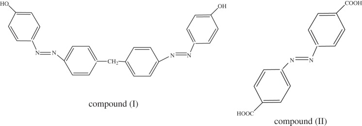
In this work, for the first time to the best of our knowledge, we report the fluorescence modulation of CdS QDs by azobenzene photochromic switches. For this purpose, we have designed and synthesized two azobenzene derivative compounds bis(4-hydroxybenzene-1-azo)4,4′(1,1′ diphenylmethane) (I) and 4,4′-azodibenzoic acid also known as 4,4′-diazenyldibenzoic acid (II) and their structures are presented in figure 1. So we proceed with a notion that photo-induced transformation of azobenzene compounds (I) and (II) from trans to cis could modulate the emission behaviour of CdS QDs by electron transfer process from the conduction band of the CdS QDs to the lowest unoccupied molecular orbital (LUMO) of the cis isomer.
Figure 1.
Structures of compound (I), Bis(4-hydroxybenzene-1-azo)4,4′(1,1′ diphenylmethane) and compound (II), 4,4′-Azodibenzoic acid also known as 4,4′-diazenyldibenzoic acid.
2. Experimental set-up
Commercially available chemicals were purchased and used without any further purification. The synthesis of surface-modified CdS QDs, CdS-(I) and CdS-(II) dyad assemblies is described as follows.
(a). Preparation of cadmium sulfide quantum dots
In order to engineer photochrome–chromophore dyad, the CdS QDs were synthesized by performing slight modifications to the procedure given by Raevskaya et al. [14]. For this purpose, ambient conditions were maintained, i.e. 25°C. A solution of 1 M CdCl2.5H2O (200 μl) was prepared in 8.42 ml of distilled water. In total, 1 M mercaptoacetic acid (MAA, 300 μl) resulted in turbidity (Cd (II)–MAA complex) that disappears on the addition of ammonia (85 μl). Finally, the sodium sulfide (0.1 M) was rapidly injected into the reaction mixture which resulted in the formation of surface-modified CdS–NH3–MAA QDs. To investigate the stability, the final solution was heated for 10 min at 90–100°C in a water bath. After the synthesis of these nanocrystals, their size was changed by varying the concentration of capping agent (MAA). For this purpose, we varied the concentration of MAA as 1 M, 2 M, 3 M, 4 M and 5 M and synthesized the samples CdS (I), CdS (II), CdS (III), CdS (IV) and CdS (V), respectively. We clearly see the difference in the colour of the final solutions of the QDs, as illustrated in figure 5b.
Figure 5.
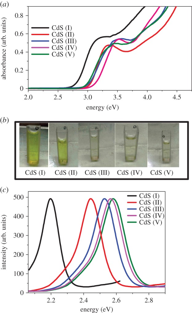
(a) Absorption spectra of CdS QDs by varying concentration of MAA, (b) Samples of CdS QDs by varying concentrationof MAA and (c) emission spectra of CdS QDs by varying concenteration of MAA. (Online version in colour.)
(b). Preparation of cadmium sulfide-(I) and -(II) dyads
For the preparation of QDs–photochromic dyad assembly, azobenzene derivatives compounds (I) and (II) were attached to the surface-modified CdS QDs. For surface modification, the thiol linkage with the CdS QDs was developed. The thiol linkage facilitates in the attachment of organic azobenzene photochromic compound (II) with surface-modified CdS QDs via a condensation type of mechanism (figure 2). Similarly, the compound (I) O–H group is eliminated, and H from the QD part; as a result sulfur makes a direct bond with the benzene ring. For this purpose, a 1 mM solution of modified CdS QDs in ethanol (10 ml), and a 1 μM solution of compounds (I) and (II) in ethanol (10 ml) were prepared. Both these solutions were then mixed together and heated at 70°C for 24–48 h under vigorous stirring, which resulted in a pale yellow transparent solution.
Figure 2.
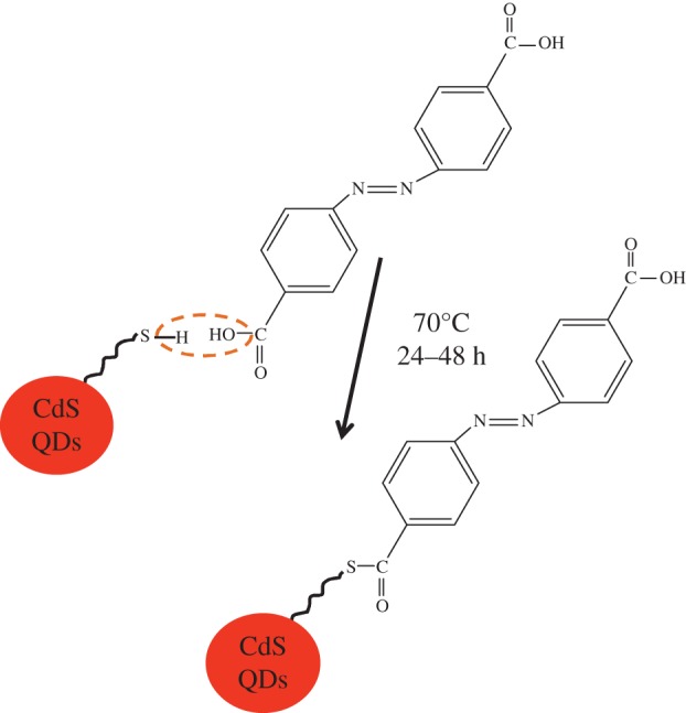
Attachment of compound (II) with surface-modified CdS QDs. (Online version in colour.)
3. Results and discussion
(a). Characterization of cadmium sulfide quantum dots
The ammonia and MAA are used to control the size of CdS QDs and for stabilizing agents. In the aqueous solution, the interaction of the MAA with the Cd (II) chloride results in the precipitation of a Cd (II) mercaptoacetate complex that causes turbidity in the solution, which is redissolved by adding ammonia to obtain the transparent solution. When Na2S is added at the final stage, it results in the formation of CdS–NH3–MAA colloids yielding a slight yellow transparent solution. These colloids showed an extra stability upon thermal treatment at 90–100°C because no change in the position of the absorption band edge was observed before and after this treatment. Instead, sharpening of the absorption feature at 3.15 eV was being observed due to the prolonged stability of the CdS–NH3–MAA colloids against precipitation and agglomeration, as illustrated by the absorption spectrum (figure 3a, black trace). In ammonia, nitrogen has a lone pair of free electrons, so it is capable of forming stable complex as compared to other bases which encompass bound electrons on nitrogen atoms. Both MAA and NH3 act as co-stabilizers, forming the blocking layer on the surface of the CdS QDs, thus prohibiting agglomeration. Fluorescence studies (figure 3b, blue trace) revealed that the sharp band edge lies in the visible region at approximately 583 nm (2.1 eV). Typically, the CdS QDs show strong photoluminescence (PL) in the range of 1.6–2.5 eV with the maximum at 2.1 eV closer to near visible region, indicating that PL originates from the recombination of the caged charge carriers (electron and holes) in deep traps introduced by surface states, which is a common feature of cadmium chalcogenides [15].
Figure 3.
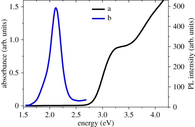
(a) Absorption spectrum of CdS QDs. (b) Emission spectrum of CdS QDs, following excitation at 353 nm (3.51 eV). (Online version in colour.)
The average diameter of synthesized CdS QDs is approximately 6 nm, which is calculated by using the Brus equation [16] with the help of the absorption spectrum (figure 3a). The calculated size of QDs from UV-vis measurements is approximately the same as the crystallite size that is calculated from X-ray diffraction (XRD) measurements (figure 4a), which is approximately 8 nm. The XRD measurements revealed three broad features at 2θ values of 27°, 45° and 52°, which matched perfectly with the (111), (220) and (311) crystalline planes of cubic zinc blende crystal structure of CdS (JCPDS=00-010-0454) [17]. The broader peaks also indicate that the QDs exist in the form of crystallites. The particle size was calculated by the following Debye Scherrer [18] equation:
| 3.1 |
where k is constant, λ is wavelength of X-rays, β is the full-width half-maximum and θ is Bragg's angle.
Figure 4.
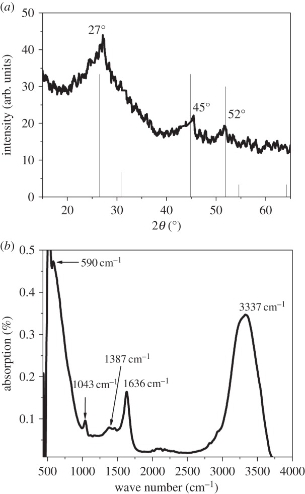
(a) XRD pattern of CdS QDs and (b) FTIR spectrum of CdS QDs.
In order to further confirm the formation of CdS QDs, Fourier transform infrared spectroscopy (FTIR) measurements were also conducted. A characteristic peak in the FTIR spectrum occurring at 590 cm−1 (figure 4b) is due to the formation of Cd-S bond, which is also consistent with the previously reported results [19]. FTIR studies also have shown the presence of various functional groups along with the formation of the CdS QDs. The peak at 1636 cm−1 is due to the C=O asymmetric stretching mode, the peak at 1387 cm−1 is due to the C=O symmetric stretching mode, the peak at 1043 cm−1 is due to the C−H bending mode and the peak at 3337 cm−1 is due to the O−H stretching mode. But the S−H stretching vibration absence at 2564 cm−1 in the FT-IR spectrum clearly indicates that the H atom has been replaced by the surface ‘Cd’ thus confirming the formation of CdS–MAA complex, which is clear indication of capping of the CdS QDs. But when the NH3 was added to the above solution the turbidity disappeared indicating that NH3 forms a complex with Cd–MAA as Cd (II)NH3–MAA.
The band edge absorption of CdS QDs is changed by varying the concentration of the capping agent MAA. As the concentration of MAA was increased the absorption edge was blue shifted (see figure 5a), i.e. 389 nm (3.18 eV), 367 nm (3.38 eV), 359 nm (3.45 eV), 356 nm (3.48 eV), 348 nm (3.56 eV) for CdS (I), CdS (II), CdS (III), CdS (IV), CdS (V) samples, respectively. Further information regarding the MAA concentration and its effect on band edge absorption is given in the electronic supplementary material, table S1. This blue shift occurs due to the quantum confinement effect [20,21], which generates several discrete energy levels compared to the bulk. As a result, these discrete energy levels give the blue shift in absorption spectra and a concomitant change in colour of the samples with different MAA concentration, which is also demonstrated in figure 5b.
Figure 5c presents the PL spectra in the range of 600 nm (2.06 eV)–425 nm (2.9 eV) showing Stokes shifted PL peaks at 568 nm (2.18 eV), 508 nm (2.44 eV), 492 nm (2.52 eV), 484 nm (2.56 eV) and 480 nm (2.58 eV) for samples CdS (I), CdS (II), CdS (III), CdS (IV) and CdS (V), respectively. The PL was measured by following excitation at a wavelength of 353 nm (3.44 eV). The observation of this Stokes shifted PL is also consistent with the previous reported work [15]. As the concentration of the capping agent increases the size of the CdS QDs decreases and it exhibits a blue shift in the PL spectra. When the particle size decreases the valence band edge shifts downwards. The emitted photon has relatively higher energy causing the PL spectrum to shift towards a lower wavelength. A quantitative relationship has also been established indicating that by increasing the MAA concentration the emission maximum has been blue shifted from 2.18 eV to 2.58 eV, which is presented in the electronic supplementary material, table S2.
As justified above, by increasing the concentration of the capping agent the size of the CdS QDs decreases. This decrease is further justified by XRD measurements in the electronic supplementary material, figure S1 and table S3. The XRD patterns for the capped CdS QDs again show a very prominent peak at 2θ values of 27°. By increasing the capping agent concentration a broadening in the peak is observed, which is a clear indication of particle size reduction. The particle size was again calculated by the Debye Scherer [18] equation (3.1).
(b). Characterization of cadmium sulfide-(I) and -(II) dyads
In order to attach the CdS QDs with azobenzene photochromic switches, the CdS QDs and the azobenzene derivatives are mixed in ethanol and heated at 70°C for 24–48 h. The synthesized models, CdS-(I) (fluorophore CdS (QDs)–photochrome (compound (I) dyad) and CdS-(II) (fluorophore CdS (QDs)–photochrome (compound (II) dyad) were characterized by UV and PL techniques.
The UV-vis spectrum revealed that the CdS QDs capped with NH3–MAA complex showed the band edge absorption at 382 nm (3.25 eV). The attachment of azobenzene photochromic switch compound (I) has shown a blue shift in the band edge absorption of CdS QDs while a new feature for CdS-(I) is generated at 354 nm (3.5 eV) as shown in figure 6a. We attribute this absorption feature to the π−π* transition of the trans isomer of compound (I). After attaching the CdS QDs to compound (I), the blue shift in absorption edge of CdS QDs is approximately 250 meV. Such bathochromic shift cannot be associated with deprotonation of the hydroxyl group, but we attribute it to the aggregation caused by strong π−π* interaction between the azo molecules when attached with the CdS QDs. Interestingly, the absorbance at 354 nm (3.5 eV) increased with the passage of reaction time. By monitoring the absorbance at various time intervals, we found that the absorbance did not change after 48 h. This suggests that by increasing the reaction time the number of molecules of compound (I) attached to the CdS QDs increases and after 48 h the number of sites which are available to accommodate the compound (I) is saturated and as a result we do not see any increase in the absorbance intensity of the feature at 354 nm (3.5 eV).
Figure 6.
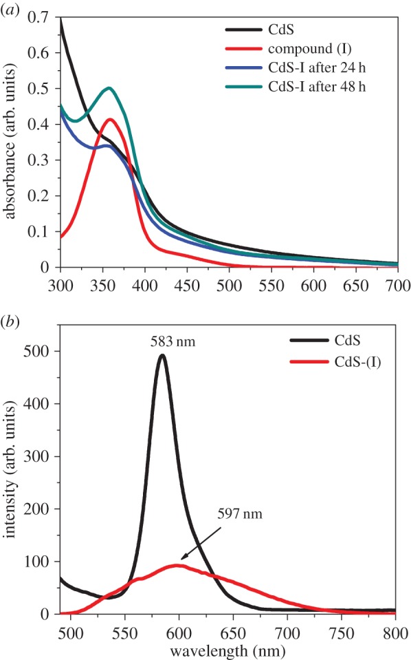
(a) Absorption spectra of surface-modified CdS QDs with thiol linkage and CdS-(I) dyad and (b) PL spectra of CdS QDs and CdS-(I) dyad following excitation at a wavelength of 353 nm (3.51 eV). (Online version in colour.)
After excitation at 353 nm (3.51 eV), the PL spectrum of bare CdS QDs show maximum emission intensity at 583 nm (2.13 eV) with a very narrow band in emission energies with a slight extended red tail (figure 6b). As justified above, this red tail may occur due to the states introduced by the capping agent and our results also agree with previous findings [16]. The red trace in figure 6b corresponds to the PL of CdS-(I) dyad, i.e. QDs attached to compound (I) and it can be clearly seen that the intensity of the emission peak is decreased approximately by approximately five times when compared with bare CdS QDs, and also there is slight red shift in the peak. We have also measured the PL of compound (I) without the presence of CdS QDs. The PL and the absorption spectra of compound (I) are reported in the electronic supplementary material, figure S2. The PL of compound (I) differs completely from the PL of CdS-(I) dyad, confirming that the PL of CdS has been modulated by compound (I). The reason for this luminescence quenching is that when the band gap at 389 nm (3.18 eV) of surface-modified CdS QDs is tuned with the absorbing state 354 nm (3.5 eV) of azobenzene photochromic compound (I), the electron transfers from QDs to the cis isomer of azobenzene. The PL quenching has also been observed in other relevant systems, for instance core–shell (CdSe–ZnS) QDs attached to [1,3] oxazines and 4,4′-bipyridinium dications [22]. In this system, the photo-excited electron in CdSe QDs is transferred to 4,4′-bipyridinium dications, which demonstrated a depressive effect on the luminescence intensity of CdSe QDs.
The photochrome azobenzene derivative compound (I) has two azo functional groups, while compound (II) has only one azo functional group. In order to check the trans–cis transformation of one azo functional group and its effect on PL modulation of CdS QDs, we also attached compound (II) to the surface-modified CdS QDs and studied its effect on PL. The UV-vis spectrum of compound (II) showed two absorbance features (figure 7a): one at 304 nm (4.08 eV) is due to π−π* transition in the trans isomer and the absorbance peak at 423 nm (2.93 eV) is due to n−π* transition in the cis isomer [23]. When it is attached to the CdS QDs, the emergence of a new feature at 333 nm (3.72 eV) corresponds to the π−π* transition of the trans form of compound (II). After attachment of compound (II) to CdS QDs, the band edge absorption of QDs shifts from 393 nm (3.15 eV) to 333 nm (3.72 eV). This blue shift is approximately 57 meV, which can be attributed to the aggregation caused by the strong π−π* interaction of the azo functional group of compound (II). Further, it can be noticed that with the increase in the reaction time the peak intensity in the absorbance feature at 333 nm (3.72 eV) increases, and after 24 h the feature at 423 nm (2.93 eV) still persists but after 48 h this peak disappears with a concomitant increase in intensity of the feature appearing at 333 nm (3.72 eV). By further increasing the reaction time, the peak intensities and their positions do not alter.
Figure 7.
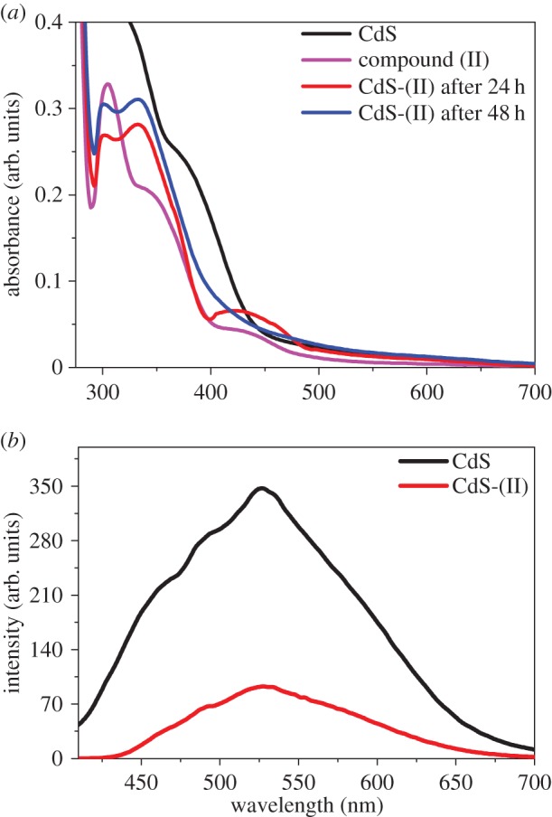
(a) Absorption spectra of modified CdS QDs with thiol linkage and CdS-(II) dyad and (b) PL spectra of CdS QDs and CdS-(II) dyad following excitation at a wavelength 389 nm (3.51 eV). (Online version in colour.)
The PL spectrum displayed in figure 7b for CdS QDs showed a strong emission peaking at 528 nm (2.35 eV) following excitation at 353 nm (3.51 eV). But the attachment of compound (II) on the surface of CdS QDs suppresses the PL by approximately five times that of the bare CdS QDs. This is due to the electron transfer from the CdS QDs to the cis isomer of photochromic compound (II).
In both cases, the interconversion from the trans to the cis isomer helps to tune the energy states of the photochrome such that the photo-excited electron of the conduction band of CdS QDs is transferred to the cis isomer of compounds (I) and (II). As a result, strong PL quenching has been observed in surface-modified CdS QDs attached to compounds (I) and (II). The photo-induced interconversion of spiropyran into the merocyanine isomer and the electron transfer from CdSe–ZnS (core–shell) nanoparticles to the merocyanine isomer have been reported previously [9]. In our case, the energy of the LUMO of the azobenzene photochromic compounds (I) and (II) reduction potential should decrease below that of the conduction band of the CdS QDs only after photochromic transformation, as illustrated in figure 8a. The photochromic transformation takes place from the trans to the cis isomer. The energy gap between the LUMO and HOMO level is greater in trans isomer than in cis isomer, which results in either the decrease of LUMO level or the increase of the highest occupied molecular orbital (HOMO) level than that of CdS QDs after photochromic transformation. As a result, electron transfer takes place from CdS QDs to the LUMO of the cis isomer of the photochromic compounds (I) and (II), which results in quenching of PL of CdS QDs illustrated in figure 8b. In this case, photochrome compounds act as acceptors. We have also observed reversible photoswitching behaviour of azobenzene photochromic compound (II). The intensity of the absorption feature at 304 nm (4.08 eV) in figure 7a decreased as a result of trans to cis isomerization of azobenzene photochrome compound (II) upon ultraviolet irradiation at 333 nm (3.72 eV), and the original isomerization was fully restored (figure 9) upon storage in the dark after thermal cis–trans reisomerization.
Figure 8.
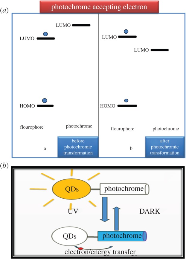
(a) Mechanism of electron transfer from CdS QDs to photochromic compound and (b) modulation ofluminescence of QDs by photoisomerization of a photochromic azobenzene. (Online version in colour.)
Figure 9.
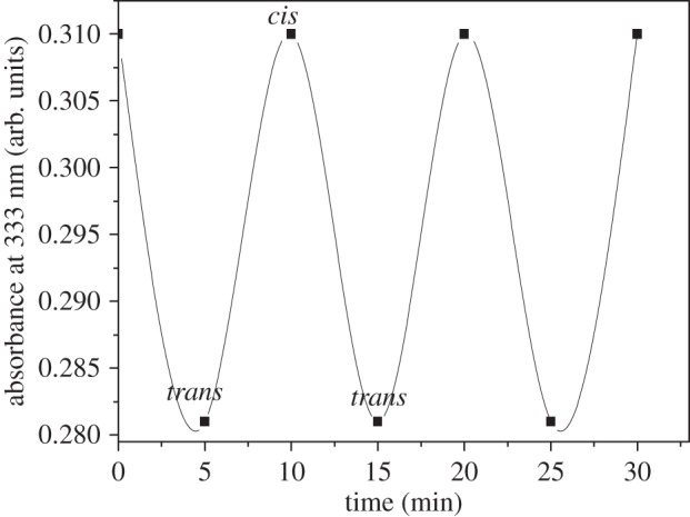
Photoswitching behaviour of cis–trans transformation of compound (II) by UV irradiation.
The previous reports suggested that surface-modified QDs with thiol linkage can easily be attached to inorganic photochromes [10,24]. In this case, by varying the concentration of the capping agent (MAA), we have controlled the size of CdS QDs and their crystallite size. Furthermore, spectroscopic studies revealed that the attachment of azobenzene photochromic compounds (I) and (II) with CdS QDs depends on the reaction time. The trans azobenzene photochromes retained their properties even after the attachment. Specifically, the UV irradiation causes the trans–cis isomerization of azobenzene which was thermally reversible. The CdS QDs with the thiol linkage provided the best site for the attachment of azobenzene derivatives compounds (I) and (II), which resulted in the luminescence quenching of CdS-(I) and CdS-(II) dyads approximately by five times that of bare CdS QDs.
Future experiments will be designed to study the mechanism of electron transfer via time-resolved fluorescence and time-resolved transient absorption measurements. In these experiments, the electron transfer rate from the QDs to the photochrome will be studied. These studies will help to develop understanding to devise efficient fluorescence modulators that could potentially be used in bioimaging and also for data storage applications.
4. Conclusion
The CdS QDs were synthesized and their surface was modified by using the capping agent MAA. In aqueous solution, the interaction of MAA with Cd (II) chloride resulted in the precipitation of the Cd (II) mercaptoacetate complex. The addition of Na2S formed CdS–NH3–MAA colloids. By increasing the concentration of MAA, the QDs size was decreased from approximately 10 nm to 6 nm. This decrease was confirmed by XRD measurements, where a broadening in the XRD features was observed. As the concentration of MAA increased from 1 to 5 M due to the quantum confinement effect, the absorption band edge was blue shifted from approximately 3.15–3.56 eV. Correspondingly, the sharp band edge emission peak occurring in the visible region at approximately 2.18 eV was concomitantly blue shifted to 2.58 eV upon increasing MAA concentration. The surface-modified CdS QDs were successfully attached via thiol linkage with azobenzene photochromic compounds (I) and (II), forming CdS-(I) and CdS-(II) dyad assemblies, respectively. The photo-induced trans–cis transformation of azobenzene photochromic compounds (I) and (II) in the CdS-(I) and CdS-(II) dyads facilitated electron transfer from the conduction band of the CdS QDs to the LUMO of the cis isomer of the photochromic compounds. This caused a strong suppression approximately five times that of PL in CdS-(I) and CdS-(II) dyads when compared with the bare CdS QDs. The thermal regeneration of the original state (trans isomer) of compounds (I) and (II) can prevent permanent quenching and restore the original fluorescence intensity. The fluorescence modulation in such systems can help to design luminescent probes for bioimaging and may help to devise data storage devices.
Supplementary Material
Supplementary Material
Acknowledgements
This work was performed within the Department of Chemistry Quaid-i-Azam University Islamabad. We gratefully acknowledge financial support by Higher Education Commission (HEC) Pakistan and the authors thank and acknowledge the experimental assistance and helpful discussions with M. Sohail, Z. H. Shah, N, Bibi, S. Saeed and Z. Siddique.
Data accessibility
Change in absorption edge of CdS QDs, blue-shifted emission of CdS QDs, reduction in particle size by increasing the MAA concentration, synthesis of compounds (I) and (II) and absorption and fluorescence of compounds (I) and (II) is available free of charge via the Internet at http://rspa.royalsocietypublishing.org.
Authors' contributions
All authors contributed equally to this study.
Competing interests
The authors declare no competing financial interest.
Funding
The work reported in this paper was financially supported by Higher Education Commission (HEC) of Pakistan through equipment/research grant nos. (PD-IPFP/HRD/HEC/2013/1983) and (20-3071/NRPU/R&D/HEC/13).
References
- 1.Leutwyler WK, Bürgi SL, Burgl H. 1996. Semiconductor clusters, nanocrystals, and quantum dots. Science 271, 933–937. (doi:10.1126/science.271.5251.933) [Google Scholar]
- 2.Nozik AJ, Beard MC, Luther JM, Law M, Ellingson RJ, Johnson JC. 2010. Semiconductor quantum dots and quantum dot arrays and applications of multiple exciton generation to third-generation photovoltaic solar cells. Chem. rev. 110, 6873–6890. (doi:10.1021/cr900289f) [DOI] [PubMed] [Google Scholar]
- 3.Osaki F, Kanamori T, Sando S, Sera T, Aoyama Y. 2004. A quantum dot conjugated sugar ball and its cellular uptake. On the size effects of endocytosis in the subviral region. J. Am. Chem. Soc. 126, 6520–6521. (doi:10.1021/ja048792a) [DOI] [PubMed] [Google Scholar]
- 4.Konstantatos G, Howard I, Fischer A, Hoogland S, Clifford J, Klem E, Levina L, Sargent EH. 2006. Ultrasensitive solution-cast quantum dot photodetectors. Nature 442, 180–183. (doi:10.1038/nature04855) [DOI] [PubMed] [Google Scholar]
- 5.Rothman JH, Still WC. 1999. A new generation of fluorescent chemosensors demonstrate improved analyte detection sensitivity and photobleaching resistance. Bioorg. Med. Chem. lett. 9, 509–512. (doi:10.1016/S0960-894X(99)00045-1) [DOI] [PubMed] [Google Scholar]
- 6.Lemon BI, Crooks RM. 2000. Preparation and characterization of dendrimer-encapsulated CdS semiconductor quantum dots. J. Am. Chem. Soc. 122, 12 886–12 887. (doi:10.1021/ja0031321) [Google Scholar]
- 7.Rayevska OE, Grodzyuk GY, Dzhagan VM, Stroyuk OL, Kuchmiy SY, Plyusnin VF, Grivin VP, Valakh MY. 2010. Synthesis and characterization of white-emitting CdS quantum dots stabilized with polyethylenimine. J. Phys. Chem. C 114, 22 478–22 486. (doi:10.1021/jp108561u) [Google Scholar]
- 8.Fukaminato T, Hirose T, Doi T, Hazama M, Matsuda K, Irie M. 2014. Molecular design strategy toward diarylethenes that photoswitch with visible light. J. Am. Chem. Soc. 136, 17 145–17 154. (doi:10.1021/ja5090749) [DOI] [PubMed] [Google Scholar]
- 9.Yildiz I, Deniz E, Raymo FM. 2009. Fluorescence modulation with photochromic switches in nanostructured constructs. Chem. Soc. Rev. 38, 1859–1867. (doi:10.1039/b804151m) [DOI] [PubMed] [Google Scholar]
- 10.Tomasulo M, Yildiz I, Raymo FM. 2007. Nanoparticle-induced transition from positive to negative photochromism. Inorg. Chim. Acta 360, 938–944. (doi:10.1016/j.ica.2006.07.029) [Google Scholar]
- 11.Fukaminato T, Sasaki T, Kawai T, Tamai N, Irie M. 2004. Digital photoswitching of fluorescence based on the photochromism of diarylethene derivatives at a single-molecule level. J. Am. Chem. Soc. 126, 14 843–14 849. (doi:10.1021/ja047169n) [DOI] [PubMed] [Google Scholar]
- 12.Matsuda K, Irie M. 2004. Diarylethene as a photoswitching unit. J. Photochem. Photobiol. C: Photochem. Rev. 5, 169–182. (doi:10.1016/S1389-5567(04)00023-1) [Google Scholar]
- 13.Beharry AA, Sadovski O, Woolley GA. 2011. Azobenzene photoswitching without ultraviolet light. J. Am. Chem. Soc. 133, 19 684–19 687. (doi:10.1021/ja209239m) [DOI] [PubMed] [Google Scholar]
- 14.Raevskaya AE, Stroyuk OL, Solonenko DI, Dzhagan VM, Lehmann D, Kuchmiy SY, Plyusnin VF, Zahn DRT. 2014. Synthesis and luminescent properties of ultrasmall colloidal CdS nanoparticles stabilized by Cd(II) complexes with ammonia and mercaptoacetate. J. Nanopart. Res. 16, 2650 (doi:10.1007/s11051-014-2650-5) [Google Scholar]
- 15.Singh S, Garg S, Chahal J, Raheja K, Singh D, Singla M. 2013. Luminescent behavior of cadmium sulfide quantum dots for gallic acid estimation. Nanotechnology 24, 115602 (doi:10.1088/0957-4484/24/11/115602) [DOI] [PubMed] [Google Scholar]
- 16.Rao BS, Kumar BR, Reddy VR, Rao TS. 2011. Preparation and characterization of CdS nanoparticles by chemical co-precipitation technique. Chalcogenide Lett. 8, 177–185. [Google Scholar]
- 17.Soltani N, Gharibshahi E, Saion E. 2012. Band gap of cubic and hexagonal cds quantum dots-experimental and theoretical studies. Chalcogenide Lett. 9, 321–328. [Google Scholar]
- 18.Tyagi C, Sharma A, Kurchania R. 2014. Synthesis of CDs quantum dots using wet chemical co-precipitation method. J. Non-Oxide Glasses 6, 23–26. [Google Scholar]
- 19.Kotkata M, Masoud A, Mohamed M, Mahmoud E. 2009. Synthesis and structural characterization of CdS nanoparticles. Physica E: Low-dimens. Syst. Nanostruct. 41, 1457–1465. (doi:10.1016/j.physe.2009.04.020) [Google Scholar]
- 20.Shrestha KM. 2012. Modifying nanoparticle shape by choice of synthetic method: nanorods, spheres, mutipods, and gels. Kansas State University. [Google Scholar]
- 21.Zhang LZ, Sun W, Cheng P. 2003. Spectroscopic and theoretical studies of quantum and electronic confinement effects in nanostructured materials. Molecules 8, 207–222. (doi:10.3390/80100207) [Google Scholar]
- 22.Yildiz I, Tomasulo M, Raymo FM. 2008. Electron and energy transfer mechanisms to switch the luminescence of semiconductor quantum dots. J. Mater. Chem. 18, 5577–5584. (doi:10.1039/b809952a) [Google Scholar]
- 23.Shah SM, Martini C, Ackermann J, Fages F. 2012. Photoswitching in azobenzene self-assembled monolayers capped on zinc oxide: nanodots vs nanorods. J. Colloid Interface Sci. 367, 109–114. (doi:10.1016/j.jcis.2011.10.045) [DOI] [PubMed] [Google Scholar]
- 24.Yildiz I, Ray S, Benelli T, Raymo FM. 2008. Dithiolane ligands for semiconductor quantum dots. J. Mater. Chem. 18, 3940–3947. (doi:10.1039/b806247a) [Google Scholar]
Associated Data
This section collects any data citations, data availability statements, or supplementary materials included in this article.
Supplementary Materials
Data Availability Statement
Change in absorption edge of CdS QDs, blue-shifted emission of CdS QDs, reduction in particle size by increasing the MAA concentration, synthesis of compounds (I) and (II) and absorption and fluorescence of compounds (I) and (II) is available free of charge via the Internet at http://rspa.royalsocietypublishing.org.


