Abstract
Spine intersegmental motion parameters and the resultant regional patterns may be useful for biomechanical classification of low back pain (LBP) as well as assessing the appropriate intervention strategy. Because of its availability and reasonable cost, two-dimensional (2D) fluoroscopy has great potential as a diagnostic and evaluative tool. However, the technique of quantifying intervertebral motion in the lumbar spine must be validated, and the sensitivity assessed. The purpose of this investigation was to (1) compare synchronous fluoroscopic and optoelectronic measures of intervertebral rotations during dynamic flexion–extension movements in vitro and (2) assess the effect of C-arm rotation to simulate off-axis patient alignment on intervertebral kinematics measures. Six cadaveric lumbar–sacrum specimens were dissected, and active marker optoelectronic sensors were rigidly attached to the bodies of L2–S1. Fluoroscopic sequences and optoelectronic kinematic data (0.15-mm linear, 0.17–0.20 deg rotational, accuracy) were obtained simultaneously. After images were obtained in a true sagittal plane, the image receptor was rotated in 5 deg increments (posterior oblique angulations) from 5 deg to 15 deg. Quantitative motion analysis (qma) software was used to determine the intersegmental rotations from the fluoroscopic images. The mean absolute rotation differences between optoelectronic values and dynamic fluoroscopic values were less than 0.5 deg for all the motion segments at each off-axis fluoroscopic rotation and were not significantly different (P > 0.05) for any of the off-axis rotations of the fluoroscope. Small misalignments of the lumbar spine relative to the fluoroscope did not introduce measurement variation in relative segmental rotations greater than that observed when the spine and fluoroscope were perpendicular to each other, suggesting that fluoroscopic measures of relative segmental rotation during flexion–extension are likely robust, even when patient alignment is not perfect.
Keywords: fluoroscopy, lumbar kinematics
Introduction
LBP is one of the most prevalent and costly problems facing health care systems in North America [1,2]. Although LBP is common, its cause is often difficult to determine [3], and the characteristics and clinical relevance of abnormal spinal motion are not well understood. Several fluoroscopic studies have shown differences in lumbar intersegmental motion among patients with LBP versus asymptomatic persons [4–8]. Further, nonimaging studies of lumbar functional motion performance, as measured by movement control tests or by a three-dimensional (3D) motion device, have shown the ability to differentiate between patients with LBP and normal controls [9–11]. Thus, intersegmental motion parameters and the resultant regional patterns may be useful for biomechanical classification of LBP.
Advances in kinematic methods such as fluoroscopy can facilitate quantification of intersegmental lumbar kinematics. Fluoroscopy can be thought of as dynamic radiographic imaging. An adjustable “C-arm” supports the X-ray tube and X-ray receptor, and the patient is placed between them. The X-ray tube is energized in a pulsed or continuous fashion, and a real-time projection image sequence is generated. Clinically, dynamic joint movement is generally measured using one C-arm to obtain 2D information. In a research setting, however, both one and two C-arms (biplanar approach) are being used to obtain 3D information from applying shape-matching approaches to track various native joints and implant motion [12–16].
Numerous investigators have used fluoroscopic methods to obtain 2D [17–19] and 3D [7,8,20] measurements of lumbar intervertebral motion. Although 3D measures of lumbar kinematics can provide highly detailed information about complex intervertebral kinematics, the technique requires sophisticated hardware and software for measuring images; such tools are not readily available in the clinical setting. Single-plane, 2D intervertebral kinematics, however, can be obtained with commonly available fluoroscopy units, making the use of 2D fluoroscopy as a diagnostic and evaluative tool a distinct possibility. However, the technique of quantifying intervertebral motion in the lumbar spine must be validated, and the sensitivity assessed. Further studies can then be conducted to determine whether 2D measures (imaging biomarkers) can be identified, which characterize pathology in patients with LBP.
One factor that may affect the clinical applicability of 2D fluoroscopic measures is the accuracy of the technique when a patient's spine is not properly aligned with the fluoroscopy unit. Although previous investigators have developed and tested 2D fluoroscopy methods in the lumbar spine [17], including static assessments of spine–fluoroscopy misalignment [21], none utilized dynamic in vitro motion or assessed the sensitivity of the 2D technique to off-axis rotation (misalignment of the patient or fluoroscopy unit) by using simultaneous direct measurements [22]. Therefore, the purpose of this investigation was to compare fluoroscopic measures of intervertebral rotations with highly accurate optoelectronic measures obtained simultaneously during dynamic flexion–extension movements in vitro. Further, we sought to determine the effect of misalignment of the fluoroscopic C-arm (simulating a misalignment of the patient relative to the fluoroscope) on intervertebral kinematics by assessing the agreement between fluoroscopic measures and optoelectronic data.
Methods
Cadaveric Specimen Preparation.
Following approval by the Mayo Clinic Biospecimen Committee, six cadaveric lumbar–sacrum specimens (three female and three male; mean age, 80 years) were obtained from the Mayo Anatomical Bequest program. Specimens (L1–sacrum) were harvested en bloc, and nonligamentous soft tissues were dissected from the spine. The vertebral bodies and all ligamentous structures were left intact, including the anterior longitudinal ligament, posterior longitudinal ligament, interspinous ligaments, and facet joint capsules. Kirschner wires and screws were passed into L1 and the sacrum to help secure fixation. Polymethylmethacrylate orthodontic resin was used to pot the L1 vertebral bodies in circular acrylic fixtures. The sacrum was embedded in Excalibur Die Stone resin (Garreco, Heber Springs, AR). Specimens were embedded in potting fixtures such that the midsagittal plane aligned with the midline of the fixture. Alignment of the motion plane and the midline of the fixture were ensured by attaching the fixture to the motion simulator. Before and during testing, each specimen was kept moist using toweling and saline solution.
Active marker optoelectronic sensors with 0.15-mm linear accuracy (Optotrak Certus; Northern Digital, Inc., Waterloo, ON) were attached to the bodies of L2–S1 with custom fixtures (Fig. 1). Previous studies from our laboratory [23,24] showed that rotational accuracy of the sensors ranged from 0.17 deg to 0.20 deg. Secure fixation of the sensors was provided by radiotranslucent carbon pins (ground to a square taper at one end) that were wedged into undersized holes drilled in the bone. The sensors were placed anterolaterally and posterolaterally and extended away from the spine to ensure that the view of the fluoroscopy unit would not be obstructed during testing. The sensors were 48 mm in diameter and contained three infrared markers, equally positioned every 120 deg and separated by 32 mm. Sensor size was chosen to maximize accuracy while allowing rigid fixation in the vertebral body and unobstructed visibility of the specimen in the fluoroscopic images. The potted specimen was secured in a 6 degree-of-freedom custom dynamic spine-testing device [24] such that the uppermost vertebra (L1) was subjected to flexion–extension. The position sensor (camera unit) was positioned approximately 3 m from the specimen and at a height that centered the middle camera on the specimen; this position corresponds to the factory-recommended distance for greatest accuracy.
Fig. 1.
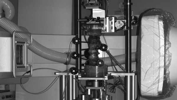
Lumbar spine specimen instrumented with active marker optoelectronic sensors and mounted in a custom spine simulator within the free space of the fluoroscope
Experimental Setup.
A digital, flat-panel, fluoroscopic C-arm (MDE Multi-Diagnostic Eleva Radiography-Fluoroscopy System; Philips Medical Systems, Best, The Netherlands) was used for fluoroscopic acquisitions. The MDE was selected for its large (60 cm) distance between the X-ray source housing and receptor surface (termed free space; a typical system has a free space of 45–50 cm) and large field-of-view (48 cm) image receptor. In addition, the digital, flat-panel image receptor provided distortion-free images without pincushion artifacts, as confirmed with a calibration grid. The patient table was removed from the C-arm, and the C-arm was then rotated to the horizontal position and centered on the lumbar specimen to optimally capture sagittal spinal motion. The specimen (mounted in the custom spine device) was located near the isocenter of the fluoroscopy unit and at a distance from the image receptor that approximated the distance in an average patient scan (Fig. 1). All the trials used a field-of-view of 30 × 38 cm and source-to-image receptor distance of 125 cm. The digital acquisition frame speed was 15 frames per second for all the trials and specimens. For this study, we did not fix the imaging parameters, so they varied during the trials; however, mA and kVp were approximately 220 and 65, respectively, for all the specimens. All the images had resolution of 512 × 512 pixels.
The spine simulator was aligned with the flat-panel image receptor using levels, and the global orthogonal coordinate system for the optoelectronic system was defined by digitizing points along each axis by using a custom digitizing stylus. The global coordinate system was defined such that it was coincident with the orientation of the fluoroscopic image receptor.
Data Collection.
The specimens were mounted in the spine simulator and placed in the free space of the C-arm. The X-ray source was oriented such that the central X-ray beam was perpendicular to the sagittal plane of the specimen. The base of the spine simulator was placed as close to the receptor as possible. The specimen was placed in a lateral position, centered anterior–posterior in the middle of the receptor, and centered cephalad–caudad at the level of L3, thereby including L1–sacrum in the field. This allowed the spine to remain centered and in the same plane for all angles acquired, a position representative of the actual location of a patient's spine during clinical fluoroscopic examinations.
Each specimen was preconditioned with five cycles of pure flexion–extension. Flexion–extension movements started from a neutral spine position and were induced by applying motion to the uppermost vertebra (L1) using displacement control at a rate of 8 deg per second, in which the 8 deg refers to global spine motion. The simulator has two passive axes of translation in the transverse plane and a third distal axial stage under load control using pneumatic methods. Three-axis gimbals and stepper motors generated motion in flexion–extension. The rate of 8 deg per second was based on simulated flexion–extension motion rates observed when patients were asked to bend forward and backward using standardized language during clinical exams. This rate is slower than many day-to-day activities but was chosen to reflect a realistic rate of motion for persons with back pain being imaged clinically. Fluoroscopic sequences were obtained simultaneously with the optoelectronic kinematic data, which was sampled at 100 Hz (MotionMonitor; Innovative Sports Training, Inc., Chicago, IL). After images were obtained in a true sagittal plane, the image receptor was rotated in 5 deg increments (posterior oblique angulations) from 5 deg to 15 deg. The 5 deg rotation increments were achieved by using the software interface on the fluoroscopy unit to rotate the C-arm about its isocenter. Flexion–extension motion was again imaged at each incremental position (5 deg, 10 deg, and 15 deg). Two flexion–extension trials were collected for each specimen and for each condition.
Dose values from future clinical use of this protocol will vary based on number of scans, speed of movement, body habitus, etc. A single dynamic fluoroscopy acquisition of the lateral spine on an average-sized adult at 15 frames per second for 8 s results in an effective dose of 0.2 mSv (assessed using a phantom). Anteroposterior and lateral lumbar spine radiographs result in an effective dose of approximately 1.5 mSv [25]. Average natural background radiation is approximately 3.0 mSv per year in the U.S. [26].
Data Analysis.
For kinematic analysis of the fluoroscopic sequences, nine frames were selected and analyzed. Frames were spaced equally through the total range of motion (ROM), with the first frame showing full extension and the final frame showing full flexion. Kinematic data from the optoelectronic and fluoroscopy systems were synchronized such that the first fluoroscopic frame corresponded to the optoelectronic frame with maximum extension and the last fluoroscopic frame corresponded to the optoelectronic frame with maximum flexion.
Using the known (analyzed) fluoroscopic frames and the frame rates for the fluoroscope and optoelectronic data, the optoelectronic frames corresponding to the analyzed fluoroscope frames were identified and analyzed. The full extension to full flexion portion of the second trial was analyzed for each condition and for each specimen. Intervertebral rotations at each motion segment (L2–L3, L3–L4, L4–L5, and L5–S1) were computed from each data set with the coordinate system fixed to the superior endplate of the inferior vertebra and the origin at the center of the endplate. The coordinate systems were setup with a custom digitizing stylus (for landmark identification), and optoelectronic data were analyzed using the commercial software (MotionMonitor); fluoroscopic images were processed using validated qma software (Medical Metrics, Inc., Houston, TX). qma is an image-processing system that tracks the motion of vertebrae through a series of radiographic images; in this study, we examined sequential frames from the fluoroscopy acquisition.
The software digitally registered images to find a best-fit match between corresponding vertebral patterns in a series of images (termed pattern matching). The tracking produced a transformation matrix that described the change in position of vertebrae from one image to the next. The matching was aided by specialized filters that minimized differences in vertebral size, shape, and grayscale to ensure optimal accuracy of the match. The matching occurred in increments of 0.125 pixels and 0.1 deg with subpixel interpolation. The regions of the vertebrae that are least sensitive to parallax effects, including the spinous processes, were emphasized during the analysis. Magnification effects were addressed through digital resizing of the images in 0.5% increments.
Intersegmental rotations were obtained at the nine intervals across the total movement for each of the four motion segments in all the six specimens. Synchronous measures were obtained from the optoelectronic data and the fluoroscopic sequences. The mean absolute difference between the optoelectronic and fluoroscopic measures of rotation was calculated to assess agreement between the two methods. First, the mean absolute difference across the nine intervals was determined individually for each specimen and fluoroscopic rotation. Second, the mean and standard deviation were determined for the mean absolute differences of all the six specimens for each given fluoroscopic rotation and motion segment. In addition, Bland and Altman limits of agreement [27] were determined for the rotation values for each motion segment in each orientation of the C-arm. A two-factor (vertebral level and C-arm rotation) analysis of variance was performed on the mean differences (statistical significance was set at P < 0.05).
Results
A representative time series of fluoroscopic and Optotrak data is depicted in Fig. 2, while mean rotational ranges of motion for the fluoroscopic- and optoelectronic-assessed spinal motion are shown in Fig. 3 and Table 1. The two-factor analysis of variance showed that off-axis rotations of the fluoroscope did not affect the mean rotation differences between the optoelectronic values and dynamic fluoroscopic values (P > 0.05). As shown in Fig. 4, the mean absolute differences were less than 0.5 deg for all the motion segments at each off-axis fluoroscopic rotation. The limits of agreement between optoelectronic values and dynamic fluoroscopic values were relatively consistent for all the off-axis rotations, ranging from −1.51 deg to 0.62 deg for the lower limit and 0.69 deg to 1.47 deg for the upper limit (Table 2 and Fig. 5). The limits were approximately evenly distributed about a zero difference value, indicating a lack of bias in the measures.
Fig. 2.
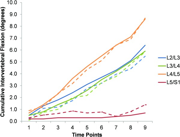
Representative cumulative intervertebral data for all motion segments in the aligned condition (fluoro = solid lines and Optotrak = dashed lines)
Fig. 3.
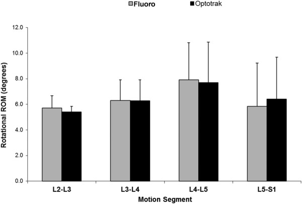
Comparison of mean (SD) rotational ROM assessed by fluoroscopy and optoelectronics
Table 1.
Rotational range of motion for assessment of spinal motion by fluoroscopy (medical metrics) versus active marker sensors (Optotrak)
| Motion segment | Fluoro, mean (SD), deg | Optotrak, mean (SD), deg |
|---|---|---|
| L2–L3 | 5.7 (0.9) | 5.4 (0.4) |
| L3–L4 | 6.3 (1.6) | 6.3 (1.6) |
| L4–L5 | 7.9 (2.9) | 7.7 (3.2) |
| L5–S1 | 5.9 (3.4) | 6.4 (3.3) |
| L2–S1 (total) | 25.8 (5.4) | 25.8 (5.5) |
Fig. 4.
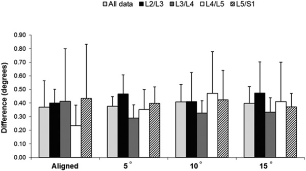
Comparison of mean absolute differences for fluoroscopy versus optoelectronic-assessed spinal motion. The mean absolute difference was calculated for each individual specimen; the graph shows the mean (SD) of the mean absolute differences for all the six specimens. The only motion segments showing significantly different mean absolute differences were L2–L3 and L3–L4.
Table 2.
Bland–Altman limits of agreement for each off-axis fluoroscopic rotation and motion segment
|
Rotation, 95% confidence limita |
||||
|---|---|---|---|---|
| Motion segment | Aligned | 5 deg | 10 deg | 15 deg |
| All motion segments | −1.09 to 1.11 | −0.86 to 1.00 | −0.91 to 1.18 | −1.04 to 1.03 |
| L2–L3 only | −0.72 to 1.15 | −1.09 to 1.30 | −1.11 to 1.28 | −1.38 to 1.22 |
| L3–L4 only | −1.18 to 1.47 | −0.87 to 0.71 | −0.90 to 0.94 | –0.80 to 0.86 |
| L4–L5 only | −0.64 to 0.77 | −0.62 to 1.02 | −1.09 to 1.43 | −1.16 to 1.18 |
| L5–S1 only | −1.51 to 0.69 | −0.90 to 0.98 | −0.68 to 1.16 | −0.97 to 1.03 |
The upper and lower limits of agreement are symmetric about the mean difference, by definition.
Fig. 5.
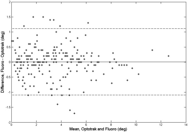
Bland and Altman plot showing fluoroscopy–Optotrak differences versus the mean values for all the specimens in the aligned condition
Discussion
To the best of our knowledge, the current study is the first to directly compare dynamic 2D fluoroscopic measures of cadaveric lumbar spinal motion (using a specialized image analysis technique) with a highly accurate optoelectronic motion measurement system. To completely describe any spinal motion, 3D kinematics must be determined. Investigators have previously used biplanar fluoroscopy techniques to determine 3D spine kinematics [7,8,20,28]. This type of analysis more completely describes spinal motion but is very resource intensive. Use of a single fluoroscope, without accompanying shape-matching techniques that have been employed previously for 3D measures [12,29], limits the analysis to planar (2D) motion in the spine, but for flexion–extension movements of the lumbar spine in the sagittal plane, purely planar motion is a reasonable assumption [22]. We believe that a method for determining 2D lumbar spine kinematics from fluoroscopic imaging could have meaningful clinical utility in tracking spinal motion during flexion–extension. However, the technique must be compared with a highly accurate measurement method to assess its sensitivity for quantifying intervertebral motion in the lumbar spine.
For the aligned condition in the current study, the 95% confidence limit for relative vertebral rotations between the optoelectronic values and the dynamic fluoroscopic values obtained from qma was within 1.51 deg (1.47 deg and 1.51 deg for upper and lower limits, respectively) for all the motion segments. Interestingly, each of the off-axis fluoroscopic rotation conditions (5 deg, 10 deg, and 15 deg) had similar 95% confidence limits for relative vertebral rotations. Variation in confidence limits was observed for each motion segment, independent of off-axis rotation, but no statistically significant differences or trends were reported. Likewise, the mean absolute differences between optoelectronic values and the dynamic fluoroscopic values showed similar trends.
Our study is not without limitations. It was an in vitro study and thus may not completely replicate the imaging conditions for in vivo studies (due to the lack of soft tissue); therefore, results reflect a best-case accuracy. Additionally, we recognize that the optoelectronic system has some measurement variation; however, to the best of our knowledge, it is the most accurate dynamic measurement technique available. We have assumed that patients can be aligned to within 15 deg of true perpendicular with the fluoroscope, but patients with rotary scoliosis or other multiplane deformity may challenge this assumption. Further, the study was not powered to assess the differences between optoelectronic values and fluoroscopic values as a function of vertebral level. We do not recommend generalizing our results to patients with multiplane deformities because we introduced rotations only of the complete lumbar spine and not of individual spinal segments. Additionally, variability of measured rotations during flexion–extension must be considered relative to the accuracy of the “best condition” images, i.e., when the specimen is perfectly aligned with the fluoroscope.
In conclusion, small misalignments (≤15 deg of rotation) of the lumbar spine relative to the fluoroscope do not introduce measurement variation in relative segmental rotations in the sagittal plane greater than that observed when the spine and fluoroscope are perpendicular to each other. This tolerance for minor misalignments suggests that fluoroscopic measures of segmental flexion–extension are likely robust, even when patient alignment is not perfect. This is in agreement with previous research [17,22]. We acknowledge that these findings are specific to the analysis of intervertebral motion using the qma technique and may not be applicable to other techniques that rely on different methods or algorithms to measure intervertebral motion. In addition, these results are specific to posterior oblique rotations (misalignments); results cannot be extended to other types of misalignments.
Acknowledgment
This research was supported by Grant No. R21 AT003957 from the National Institutes of Health (USA)/National Center for Complementary and Alternative Medicine.
Contributor Information
Kristin D. Zhao, Department of Physical Medicine and Rehabilitation, , Mayo Clinic, , Rochester, MN 55905
Ephraim I. Ben-Abraham, Division of Orthopedic Research, , Mayo Clinic, , Rochester, MN 55905
Dixon J. Magnuson, Department of Radiology, , Mayo Clinic, , Rochester, MN 55905
Jon J. Camp, Department of Physiology and Biomedical Engineering, , Mayo Clinic, , Rochester, MN 55905
Lawrence J. Berglund, Division of Orthopedic Research, , Mayo Clinic, , Rochester, MN 55905
Kai-Nan An, Division of Orthopedic Research, , Mayo Clinic, , Rochester, MN 55905.
Gert Bronfort, Center for Spirituality and Healing, , University of Minnesota, , Minneapolis, MN 55455.
Ralph E. Gay, Department of Physical Medicine and Rehabilitation, , Mayo Clinic, , Rochester, MN 55905 , e-mail: gay.ralph@mayo.edu.
Abbreviations
- LBP =
low back pain
- 2D =
two-dimensional
- 3D =
three-dimensional
References
- [1]. Frymoyer, J. W. , 1988, “ Back Pain and Sciatica,” N. Engl. J. Med., 318(5), pp. 291–300. 10.1056/NEJM198802043180506 [DOI] [PubMed] [Google Scholar]
- [2]. Katz, J. N. , 2006, “ Lumbar Disc Disorders and Low-Back Pain: Socioeconomic Factors and Consequences,” J. Bone Jt. Surg., 88(Suppl. 2), pp. 21–24. 10.2106/JBJS.E.01273 [DOI] [PubMed] [Google Scholar]
- [3]. Borenstein, D. G. , 1999, “ Epidemiology, Etiology, Diagnostic Evaluation, and Treatment of Low Back Pain,” Curr. Opin. Rheumatol., 11(2), pp. 151–157. 10.1097/00002281-199903000-00012 [DOI] [PubMed] [Google Scholar]
- [4]. Takayanagi, K. , Takahashi, K. , Yamagata, M. , Moriya, H. , Kitahara, H. , and Tamaki, T. , 2001, “ Using Cineradiography for Continuous Dynamic-Motion Analysis of the Lumbar Spine,” Spine, 26(17), pp. 1858–1865. 10.1097/00007632-200109010-00008 [DOI] [PubMed] [Google Scholar]
- [5]. Okawa, A. , Shinomiya, K. , Komori, H. , Muneta, T. , Arai, Y. , and Nakai, O. , 1998, “ Dynamic Motion Study of the Whole Lumbar Spine by Videofluoroscopy,” Spine, 23(16), pp. 1743–1749. 10.1097/00007632-199808150-00007 [DOI] [PubMed] [Google Scholar]
- [6]. Ahmadi, A. , Maroufi, N. , Behtash, H. , Zekavat, H. , and Parnianpour, M. , 2009, “ Kinematic Analysis of Dynamic Lumbar Motion in Patients With Lumbar Segmental Instability Using Digital Videofluoroscopy,” Eur. Spine J., 18(11), pp. 1677–1685. 10.1007/s00586-009-1147-x [DOI] [PMC free article] [PubMed] [Google Scholar]
- [7]. Li, W. , Wang, S. , Xia, Q. , Passias, P. , Kozanek, M. , Wood, K. , and Li, G. , 2011, “ Lumbar Facet Joint Motion in Patients With Degenerative Disc Disease at Affected and Adjacent Levels: An In Vivo Biomechanical Study,” Spine, 36(10), pp. E629–637. 10.1097/BRS.0b013e3181faaef7 [DOI] [PMC free article] [PubMed] [Google Scholar]
- [8]. Passias, P. G. , Wang, S. , Kozanek, M. , Xia, Q. , Li, W. , Grottkau, B. , Wood, K. B. , and Li, G. , 2011, “ Segmental Lumbar Rotation in Patients With Discogenic Low Back Pain During Functional Weight-Bearing Activities,” J. Bone Jt. Surg., 93(1), pp. 29–37. 10.2106/JBJS.I.01348 [DOI] [PMC free article] [PubMed] [Google Scholar]
- [9]. Ferguson, S. A. , Marras, W. S. , Burr, D. L. , Woods, S. , Mendel, E. , and Gupta, P. , 2009, “ Quantification of a Meaningful Change in Low Back Functional Impairment,” Spine, 34(19), pp. 2060–2065. 10.1097/BRS.0b013e3181b34764 [DOI] [PubMed] [Google Scholar]
- [10]. Luomajoki, H. , Kool, J. , de Bruin, E. D. , and Airaksinen, O. , 2008, “ Movement Control Tests of the Low Back; Evaluation of the Difference Between Patients With Low Back Pain and Healthy Controls,” BMC Musculoskeletal Disord., 9(170), pp. 1–12. 10.1186/1471-2474-9-170 [DOI] [PMC free article] [PubMed] [Google Scholar]
- [11]. Marras, W. S. , Ferguson, S. A. , Gupta, P. , Bose, S. , Parnianpour, M. , Kim, J. Y. , and Crowell, R. R. , 1999, “ The Quantification of Low Back Disorder Using Motion Measures. Methodology and Validation,” Spine, 24(20), pp. 2091–2100. 10.1097/00007632-199910150-00005 [DOI] [PubMed] [Google Scholar]
- [12]. Banks, S. A. , and Hodge, W. A. , 1996, “ Accurate Measurement of Three-Dimensional Knee Replacement Kinematics Using Single-Plane Fluoroscopy,” IEEE Trans. Biomed. Eng., 43(6), pp. 638–649. 10.1109/10.495283 [DOI] [PubMed] [Google Scholar]
- [13]. Bey, M. J. , Zauel, R. , Brock, S. K. , and Tashman, S. , 2006, “ Validation of a New Model-Based Tracking Technique for Measuring Three-Dimensional, In Vivo Glenohumeral Joint Kinematics,” ASME J. Biomech. Eng., 128(4), pp. 604–609. 10.1115/1.2206199 [DOI] [PMC free article] [PubMed] [Google Scholar]
- [14]. Liu, F. , Cheng, J. , Komistek, R. D. , Mahfouz, M. R. , and Sharma, A. , 2007, “ In Vivo Evaluation of Dynamic Characteristics of the Normal, Fused, and Disc Replacement Cervical Spines,” Spine, 32(23), pp. 2578–2584. 10.1097/BRS.0b013e318158cdf8 [DOI] [PubMed] [Google Scholar]
- [15]. Miranda, D. L. , Schwartz, J. B. , Loomis, A. C. , Brainerd, E. L. , Fleming, B. C. , and Crisco, J. J. , 2011, “ Static and Dynamic Error of a Biplanar Videoradiography System Using Marker-Based and Markerless Tracking Techniques,” ASME J. Biomech. Eng., 133(12), p. 121002. 10.1115/1.4005471 [DOI] [PMC free article] [PubMed] [Google Scholar]
- [16]. Wang, S. , Passias, P. , Li, G. , Li, G. , and Wood, K. , 2008, “ Measurement of Vertebral Kinematics Using Noninvasive Image Matching Method: Validation and Application,” Spine, 33(11), pp. E355–361. 10.1097/BRS.0b013e3181715295 [DOI] [PubMed] [Google Scholar]
- [17]. Breen, A. C. , Muggleton, J. M. , and Mellor, F. E. , 2006, “ An Objective Spinal Motion Imaging Assessment (OSMIA): Reliability, Accuracy and Exposure Data,” BMC Musculoskeletal Disord., 7(1), pp. 1–10. 10.1186/1471-2474-7-1 [DOI] [PMC free article] [PubMed] [Google Scholar]
- [18]. Teyhen, D. S. , Flynn, T. W. , Bovik, A. C. , and Abraham, L. D. , 2005, “ A New Technique for Digital Fluoroscopic Video Assessment of Sagittal Plane Lumbar Spine Motion,” Spine, 30(14), pp. E406–413. 10.1097/01.brs.0000170589.47555.c6 [DOI] [PubMed] [Google Scholar]
- [19]. Zheng, Y. , Nixon, M. S. , and Allen, R. , 2003, “ Lumbar Spine Visualisation Based on Kinematic Analysis From Videofluoroscopic Imaging,” Med. Eng. Phys., 25(3), pp. 171–179. 10.1016/S1350-4533(02)00182-0 [DOI] [PubMed] [Google Scholar]
- [20]. Aiyangar, A. K. , Zheng, L. , Tashman, S. , William, J. A. , and Xudong, Z. , 2014, “ Capturing Three-Dimensional In Vivo Lumbar Intervertebral Joint Kinematics Using Dynamic Stereo-X-Ray Imaging,” ASME J. Biomech. Eng., 136(1), p. 011004. 10.1115/1.4025793 [DOI] [PubMed] [Google Scholar]
- [21]. Frobin, W. , Brinckmann, P. , Leivseth, G. , Biggemann, M. , and Reikeras, O. , 1996, “ Precision Measurement of Segmental Motion From Flexion-Extension Radiographs of the Lumbar Spine,” Clin. Biomech., 11(8), pp. 457–465. 10.1016/S0268-0033(96)00039-3 [DOI] [PubMed] [Google Scholar]
- [22]. Bifulco, P. , Sansone, M. , Cesarelli, M. , Allen, R. , and Bracale, M. , 2002, “ Estimation of Out-of-Plane Vertebra Rotations on Radiographic Projections Using CT Data: A Simulation Study,” Med. Eng. Phys., 24(4), pp. 295–300. 10.1016/S1350-4533(02)00021-8 [DOI] [PubMed] [Google Scholar]
- [23]. Baltali, E. , Zhao, K. D. , Koff, M. F. , Keller, E. E. , and An, K. N. , 2008, “ Accuracy and Precision of a Method to Study Kinematics of the Temporomandibular Joint: Combination of Motion Data and CT Imaging,” J. Biomech., 41(11), pp. 2581–2584. 10.1016/j.jbiomech.2008.05.023 [DOI] [PMC free article] [PubMed] [Google Scholar]
- [24]. Ilharreborde, B. , Zhao, K. , Boumediene, E. , Gay, R. , Berglund, L. , and An, K. N. , 2010, “ A Dynamic Method for In Vitro Multisegment Spine Testing,” Orthop. Traumatol. Surg. Res., 96(4), pp. 456–461. 10.1016/j.otsr.2010.01.006 [DOI] [PubMed] [Google Scholar]
- [25]. Mettler, F. A., Jr. , Huda, W. , Yoshizumi, T. T. , and Mahesh, M. , 2008, “ Effective Doses in Radiology and Diagnostic Nuclear Medicine: A Catalog,” Radiology, 248(1), pp. 254–263. 10.1148/radiol.2481071451 [DOI] [PubMed] [Google Scholar]
- [26].NCRP, 2009, “ Ionizing Radiation Exposure of the Population of the United States,” National Council on Radiation Protection and Measurements, Bethesda, MD, Report No. 160.http://ncrponline.org/publications/reports/ncrp-report-160/
- [27]. Bland, J. M. , and Altman, D. G. , 2007, “ Agreement Between Methods of Measurement With Multiple Observations per Individual,” J. Biopharm. Stat., 17(4), pp. 571–582. 10.1080/10543400701329422 [DOI] [PubMed] [Google Scholar]
- [28]. Wang, S. , Passias, P. , Li, G. , Li, G. , and Wood, K. , 2008, “ Measurement of Vertebral Kinematics Using Noninvasive Image Matching Method-Validation and Application,” Spine, 33(11), pp. E355–361. 10.1097/BRS.0b013e3181715295 [DOI] [PubMed] [Google Scholar]
- [29]. Victor, J. , Mueller, J. K. , Komistek, R. D. , Sharma, A. , Nadaud, M. C. , and Bellemans, J. , 2010, “ In Vivo Kinematics After a Cruciate-Substituting TKA,” Clin. Orthop. Relat. Res., 468(3), pp. 807–814. 10.1007/s11999-009-1072-7 [DOI] [PMC free article] [PubMed] [Google Scholar]


