Abstract
Robotic minimally invasive surgery (R-MIS) has achieved success in various procedures; however, the lack of haptic feedback is considered by some to be a limiting factor. The typical method to acquire tool–tissue reaction forces is attaching force sensors on surgical tools, but this complicates sterilization and makes the tool bulky. This paper explores the feasibility of using motor current to estimate tool-tissue forces and demonstrates acceptable results in terms of time delay and accuracy. This sensorless force estimation method sheds new light on the possibility of equipping existing robotic surgical systems with haptic interfaces that require no sensors and are compatible with existing sterilization methods.
Keywords: sensorless force estimation, force feedback, robotic minimally invasive surgery
1. Introduction
R-MIS has been widely implemented in hospitals around the world due to its advantages of improving the accuracy and dexterity of a surgeon while minimizing trauma to the patient and has had a large impact on surgical technique in certain specialties [1]. However, because of the loss of direct contact with the surgical site, the surgeon cannot perceive tactile information, which may adversely affect surgical efficiency and/or efficacy. The lack of haptic feedback is regarded as a limiting factor in existing R-MIS technology [2].
To solve this problem, researchers have incorporated different kinds of force sensors on surgical tools to measure the tool–tissue interaction forces [3]. Based on the attached location, these sensors can be divided into two categories. The first category is sensors incorporated on the jaws; most of these sensors use strain gauges due to their small form factor [4–8], and there are also some other sensors using piezoelectric materials [9–11]. The second category is sensors attached at the distal end of the shaft; for example, Seibold et al. [12] and Kuebler et al. [13] developed a force–torque sensor with strain gauges to measure manipulation forces at the tip, and Mayer et al. attached four strain gauges on the distal end of the shaft to feed back the interaction force at the tool tip [14].
However, the employment of force sensors leads to other problems. First, the surgical tool tips are small in size; for sensors using piezoelectric materials, it is hard to incorporate them on the jaws and they also make the tools bulky and potentially impair their normal use. For sensors using strain gauges, though the size is not as problematic, there is always a tradeoff between the sensitivity of the measurement and the stiffness of the structure, since the force measurement with strain gauges is based on the measurement of structural deformation. Second, steam sterilization via autoclave is a standard method widely applied to sterilize surgical equipment, and this requires saturated steam to heat the equipment up to 121 °C at 103 kPa (gauge pressure) for at least 15 min. It is in unclear whether these sensors can survive this harsh environment [3]. Generally, current sensorized solutions require many extra system components and manufacturing steps which likely affect the economy and robustness of the surgical devices.
This paper explores the feasibility of using motor current to sensorlessly estimate the tool–tissue interaction forces. Li [15] and Jeong and Cho [16] have used this method to estimate the cutting forces on a computer numerical control (CNC) turning center and on a milling machine. Tholey et al. have tried estimating jaw force for a laparoscopic grasper based on supplied motor voltage [17], but without acceptable performance in terms of error/accuracy, and the time response has not been tested. In this project, the motions of three degree-of-freedom (3-DOF) surgical grasper have been decoupled first, and then the sensorless force estimation method is applied.
2. Motion and Force Decoupling
Estimating tool–tissue interaction force with motor current is more accurate if the driving system is decoupled, which means each motor only drives one DOF and does not affect other motions. However, existing surgical tools for R-MIS tend to have coupled motions. For example, the EndoWrist tools for the da Vinci Surgical System (Intuitive Surgical) have four DOFs (roll, yaw, pitch, and grasp) and are kinematically coupled. To apply the sensorless force estimation method on this kind of tool, it is necessary to decouple all the motions in the driving system first.
The first motion coupling between roll and yaw/pitch/grasp can be easily solved by moving the roll DOF onto the robot arm, where the tool is attached. (Thus, the whole tool assembly achieves roll about the axis of the tool shaft.) The second motion coupling between yaw and pitch/grasp requires more effort to solve.
2.1. Decoupling Theory.
To solve the coupling problem, a decoupling mechanism is proposed based on planetary gear theory [18]. Figure 1 shows a 3-DOF surgical grasper design based on this mechanism. The yaw DOF is driven by the planetary gear system, and the housing, which is rigidly attached with the second gear, is the yaw output; the two jaws are driven separately by cables, which pass the yaw joint through a series of idler pulleys. Figure 2 shows the geometry of the mechanical relationships on the top view of the linkage.
Fig. 1.
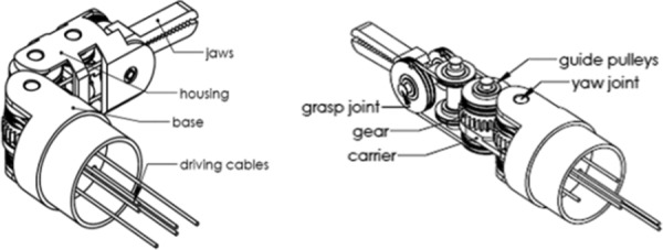
A decoupled cable-driven grasper [18]
Fig. 2.
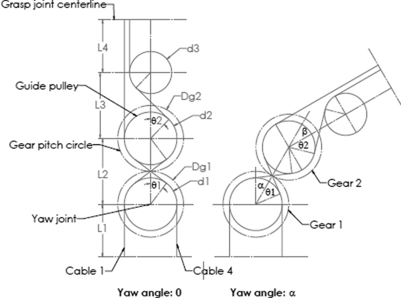
Cables driving one jaw [18]
Figure 2 shows the path of two opposing cables which drive one jaw. When analyzing the yaw DOF, the pitch and grasp DOF are assumed to be fixed, so the cable length wrapped on the grasping pulley remains constant. When the yaw angle is zero, the path length of cable 1 is
| (1) |
| (2) |
| (3) |
The lengths of cable 4 and the cables driving the other jaw take on a similar form. The path length only involves the pulley diameters d and the center distances L. (The chosen L and d should be constrained to preclude interference, consistent with the geometry shown in Fig. 2.)
With a yaw angle α, the path length of cable 1 is
| (4) |
The difference between and is
| (5) |
To make the path length independent of the yaw DOF, should be equal to , which means
| (6) |
In other words, the cable length wrapped on pulley 1 equals the cable length unwrapped from pulley 2 .
Rearranging,
| (7) |
To apply this mechanical constraint, a planetary system composed of a sun gear (gear 1), a planet gear (gear 2), and a carrier is employed. In a planetary gear system,
| (8) |
where and are the diameters of gear 1 and gear 2; , , and are velocities of gear 1, gear 2, and carrier, respectively.
Note that (with representing time)
| (9) |
| (10) |
| (11) |
From Eq. (8), if = 0 (fix the sun gear)
| (12) |
If is chosen to be equal to , then the mechanical constraint in Eq. (7) is satisfied.
Therefore, if the gear diameter ratio and another constraint relation (for example, fix the sun gear) in the planetary gear system are given, the pulley diameter ratio can be chosen to make pitch, grasp, and yaw independent.
To select cables with appropriate stiffness, a cable deformation model is also derived. As shown in Fig. 3, a jaw is driven by a pulley through a cable loop, and the driving cables are tangent with the pulley circle, which has a radius of R; the jaw has length of L, and is loaded with force T at the distal end. To prevent cable slackness, the cables are pretensioned with force F, which should be larger than the maximum cable tensile load in the application; the cable initial length under pretension is x. After applying a load T at the jaw, the cable tension change is ΔF, and the cable length change is Δx. Applying a moment balance principle at the rotation axis of the jaw,
Fig. 3.

Cable deformation model
| (13) |
Assuming the cable stiffness is k,
| (14) |
| (15) |
The position error caused by the cable deformation is
| (16) |
Using Eq. (16) with maximum anticipated load T, a cable with appropriate stiffness can be selected to meet the position error constraint.
2.2. Decoupled Prototype.
For the prototype design shown in Fig. 1, the sun gear is fixed ( = 0), the diameter ratio between gear 1 and gear 2 is chosen to be 1:1 for space efficiency, and the diameter ratio between pulley 1 and pulley 2 is set to be 1:1 to decouple the yaw DOF from grasp and pitch DOFs. Based on planetary gear theory,
| (17) |
Therefore, = 2. In this design, the carrier, which is attached on a driving pulley, is chosen to be the driving link, and gear 2 is the yaw output. This implies that the yaw output angle is double the input, as shown in Fig. 2.
A 3-DOF surgical grasper prototype has been fabricated using 3D printing at approximately 3:1 scale based on this design [19]. All the joints in the grasper tip are equipped with ball bearings to reduce friction. Monofilament nylon is used for the cable transmission (Fig. 4(a)). Two jaws are each driven independently via separate links attached to the cables, and the yaw motion is also driven by a pulley through a cable (Fig. 4(b)).
Fig. 4.
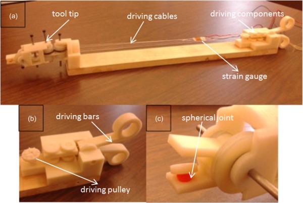
The 3DOF surgical grasper prototype
A force-sensitive resistor (FlexiForce A201, 4.4 N force range) is used to measure the grasp force; to make sure the force is uniformly distributed on the sensor, a spherical-jointed intermediate pad was placed between the jaw and the sensor (Fig. 4(c)). The grasp force measurement setup is shown in Fig. 5(a). To measure the cable force, a strain gage (Vishay MM WK-13-250AE-10C) is attached in series with one of the cables that drive the jaws (Fig. 5(b)). A protractor is used to measure the yaw angle (Fig. 5(c)).
Fig. 5.
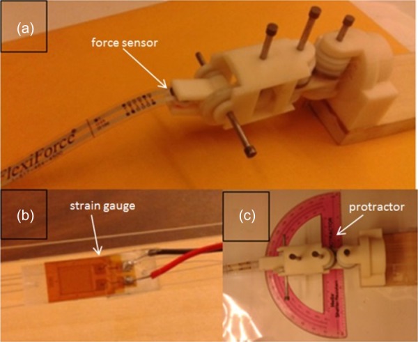
Experiment setup
2.3. Decoupling Results.
First, the motion decoupling experiment was conducted, which consisted of actuating the various DOF and observing the forward kinematics. The motion of the prototype follows the decoupling theory and matches the predicted motion of the model. (The yaw output angle is double the input, see Fig. 6.) Furthermore, the position of the two jaws remains constant independent of yaw angle. This experiment proves that the grasp motion is decoupled from the yaw motion.
Fig. 6.

Motion comparison between prototype and computer-aided design (CAD) model
Second, the force decoupling experiment was conducted. With different yaw angles, the corresponding grasp forces were measured. The result is shown in Fig. 7, which shows that these forces are not highly influenced by yaw motion (less than 10%).
Fig. 7.
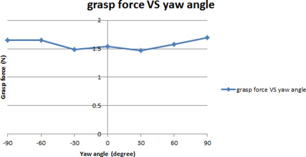
Force decoupling between grasp and yaw motion (* zero yaw angle is the position where the whole tool tip is in line with the tool shaft)
3. Tool-Tissue Force Estimation
3.1. System Modeling.
Since the driving mechanism is decoupled and each DOF is driven by a separate motor, a simplified system modeling of one of these DOFs is shown in Fig. 8. The motor, with inertia J1, drives all the rotational components on this DOF through a gear set, with gear ratio N2/N1; the combined inertia of the rotational components is J2. With output torque of T and displacement of θ at the motor, the torque produced on the rotational components is TF + Tf, where TF represents the torque to conquer the interaction force on the tool tip, and Tf represents the torque to overcome friction. Based on this modeling,
Fig. 8.
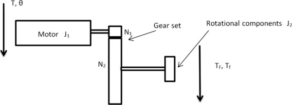
System modeling
| (18) |
The motor used in this project is a Faulhaber 2224U012S DC motor in combination with a 66:1 planetary gearhead, so N1/N2 = 1/66. Substituting into Eq. (18),
| (19) |
Since all the rotational components are 3D printed and small in size, their inertia is very small (less than 2 gcm2), and J2/4356 will be less than 0.0005 g cm2, compared with the motor inertia of J1 = 2.7 g cm2. Therefore, the contribution from the rotational components can be ignored. Based on DC motor theory, its current is linear proportional to its output torque,
| (20) |
where K represents the motor's torque constant. So it is believed that the motor output torque can be estimated from the motor current. Since general surgery is characterized by slow motions (0–2 Hz), the dynamic effect is assumed to be minimal; with appropriate handling of the friction in the mechanism, the friction effect Tf can also be assumed to be relatively small (nondominating). So finally it is believed that the torque required to overcome the interaction force on the tool tip TF can be estimated from the driving motor's current.
There are two assumptions for this method of force estimation using motor current. The jaw is driven by cables which traverse several joints, and it is assumed that the friction along the cable path can be ignored; thus the manipulation force on the jaw is linearly proportional to the cable tension. Also the motor drives the cable through a gear set, it is assumed that the friction in the gear set will not affect the linear relation between motor current and motor output torque.
First, the relation between the manipulation force on the jaw and the cable tension was tested using the prototype presented in Sec. 2.2. With different tensions in the cable, the corresponding grasp force was measured. The result is shown in Fig. 9, in which the linear relation between cable tension and grasp force is clearly shown. The first assumption is validated.
Fig. 9.
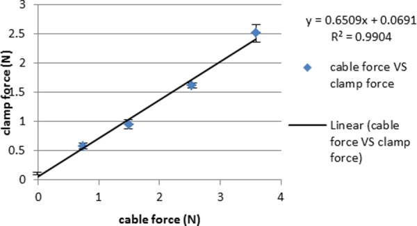
Linear relation between clamp force and cable tension [19]
Second, the relation between the motor current and the motor torque on the output shaft was tested. Applying different torque on the motor output shaft in different directions, the corresponding motor current readings from the driver unit (NI 9505 motor drive module) were recorded. Figure 10 shows the result; it is shown that no matter the direction, the motor current value has a good linear relation with the output torque, and the gearhead does not significantly affect this relation.
Fig. 10.
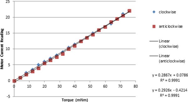
Linear relation between motor current and motor torque
3.2. Force Estimation on a Scaled Prototype.
The second prototype was built based on the one in Sec. 2.2 by motorizing the grasp, pitch, and yaw DOFs and replacing the monofilament nylon with braided polyethylene to increase stiffness (Fig. 11(a)) [20]. A 3DOF master control equipped with position sensors on each joint was also fabricated to control the grasper prototype (Fig. 11(b)). The motors in the surgical grasper prototype are controlled by a proportion integration differentiation (PID) controller with position commands coming from the master robot, and the motors' current signals are filtered by a low-pass filter with a cutoff frequency of 3 Hz. The data sampling rate is 2 kHz.
Fig. 11.

The 3DOF surgical grasper prototype and master control
Experiments have been conducted on the prototype to test the force estimation on grasp, pitch, and yaw DOFs separately. The experiment setups for the three experiments are shown in Fig. 12. The grasp force is estimated by averaging the force estimations from the driving motors of the two independent jaws based on motor current; the pitch force is estimated from the driving motor of the jaw that is in contact with the force sensor; and the yaw force is estimated from the motor that drives the yaw DOF.
Fig. 12.
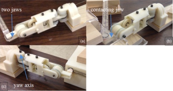
Experiment setting of force estimation on (a) grasp DOF, (b) pitch DOF, and (c) yaw DOF [20]
Experiment results show that the performance on grasp, pitch, and yaw DOFs is similar. For simplicity, only the result for the grasp test is shown graphically. Then the estimation error and time delay between force estimation and force measurement are compared for the three DOFs.
To check the reliability of this force estimation method, steady inputs lasting more than 10 s were manually applied to the grasper input cables for producing force estimations for the grasp DOF. Figure 13 shows the result by comparing the force estimations with the respective force measurements; the force shape comparisons are shown versus time in (a), and the repeated testing results are shown in (b).
Fig. 13.
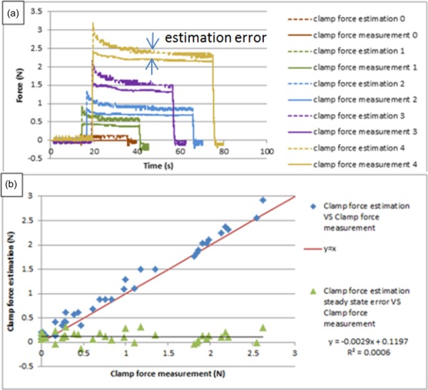
Force estimation on grasp DOF for long steady input
It is noticed that the force estimation has an initial peak at the beginning, due to dynamic effects; then the amplitude decreases slowly and finally settles to a steady state, which is slightly larger than the force measurement, due primarily to the friction in the mechanism; the error between the steady state value of force estimation and force measurement is used to characterize the accuracy of this method. The repeated testing results demonstrate that the performance of this force estimation method is relatively robust.
Since typical surgical motions during operations last 1–2 s, the force estimation method was tested with steady input lasting about 2 s on the grasp DOF. Figure 14 shows the results by comparing the force estimations with the respective force measurements; the force shape comparisons are shown versus time in (a), and the repeated testing results are shown in (b).
Fig. 14.
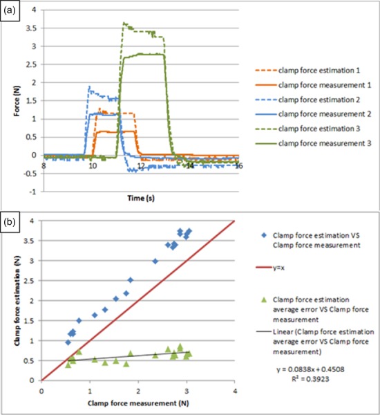
Force estimation on grasp DOF for short steady input
It is noticed that the force estimation amplitude is a little larger than the force measurement due to the friction in the mechanism, and the error is linearly increasing with the load, due to the initial peak of the force estimation. The repeated testing results demonstrate that the performance of this force estimation method is relatively robust for the short-time duration steady input.
To test the time response of this force estimation method, periodic inputs were manually applied at about 2 Hz on the grasp DOF, since voluntary surgical motions lie in the 0–2 Hz range [21]. Figure 15 shows the test results; the force shape comparisons between force estimation and force measurement are shown in (a), and two input cycles are shown in detail in (b). It is apparent that the force estimation follows the characteristic shape of the force measurement very well, with maximum latency (the time gap between force estimation peak and its corresponding force measurement peak) of 20 ms. Literature shows that 100 ms is regarded as an upper threshold for performance to be unaffected [22], so we believe the delay in this test is not a point of concern.
Fig. 15.
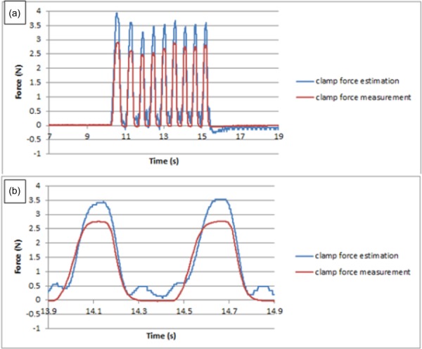
Force estimation on grasp DOF for periodic input [20]
Similar tests have been done on pitch and yaw DOFs; since the results are similar to that of the grasp DOF, we will not elaborate on them in detail. Instead, we will compare two important features (estimation error and time delay) between them. Table 1 shows the estimation errors for different inputs on the three DOFs. Table 2 shows the time delay between force estimation and force measurement on grasp, pitch, and yaw DOFs.
Table 1.
Estimation error in grasp, pitch, and yaw tests for scaled prototype (units: N)
| Long steady input | Short steady input | Periodic input | |
|---|---|---|---|
| Grasp test | 0.1121 | 0.6135 | 0.8467 |
| Pitch test | 0.39 | 1.0144 | 0.933 |
| Yaw test | 0.0811 | 0.195 | 0.23 |
Table 2.
Time delay in grasp, pitch, and yaw tests for scaled prototype (units: ms)
| Grasp test | 20 |
| Pitch test | 0 |
| Yaw test | 20 |
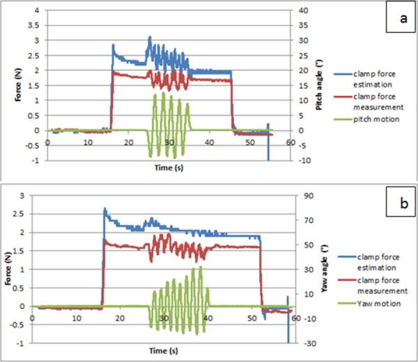
In the grasp experiment, we also tested the influence of pitch and yaw motions on the grasp force, challenging the idealized decoupling of these DOF. Figure 16 shows the results. One can notice that, in both cases, the pitch (yaw) motion induces some oscillation; this appears to be measurement noise caused by the movement of the sensor. Comparing the two figures, it is noticed that the pitch motion causes more oscillation of the force estimation than the yaw motion; this is because the pitch motion involves precisely the two motors which control the grasp motion, and the dynamic effect from the pitch motion will thus directly affect the grasp force estimation. In contrast, the yaw motion causes little influence on the grasp force estimation; this illustrates that the grasp motion/force is decoupled from yaw motion as expected based on the kinematic decoupling of the respective DOFs.
Fig. 16.
Influence of (a) pitch and (b) yaw motion on grasp force
3.3. Force Estimation on an Actual Sized Prototype.
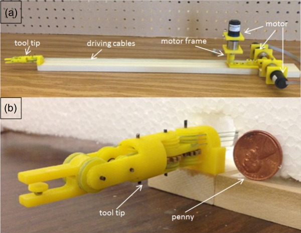
The actual surgical tools, especially the tool tip parts, are usually made of stainless steel, and the size is small, with diameter around 10 mm. To test the force estimation performance on the actual sized surgical tool, a third prototype was 3D printed, with diameter 15 mm (Fig. 17). To simulate the metal–metal friction surface on an actual surgical tool, all the joints in the tool tip are equipped with journal bearings.
Fig. 17.
The actual sized prototype
The force estimation method was tested with this prototype on grasp, pitch, and yaw DOFs, with similar experiment settings as shown in Fig. 12. Since the performance is similar on all the three DOFs, only the test result on the grasp DOF is shown, and two important features (estimation error and time delay) are compared among these DOFs in Tables 3 and 4.
Table 3.
Estimation error in grasp, pitch, and yaw tests for actual sized prototype (units: N)
| Long steady input | Short steady input | Periodic input | |
|---|---|---|---|
| Grasp test | 0.1329 | 0.4207 | 0.7443 |
| Pitch test | −0.013 | 0.0967 | −0.002 |
| Yaw test | −0.0142 | 0.1016 | 0.31 |
Table 4.
Time delay in grasp, pitch, and yaw tests for actual sized prototype (units: ms)
| Grasp test | −30 |
| Pitch test | −40 |
| Yaw test | −40 |
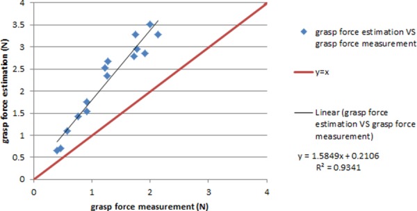
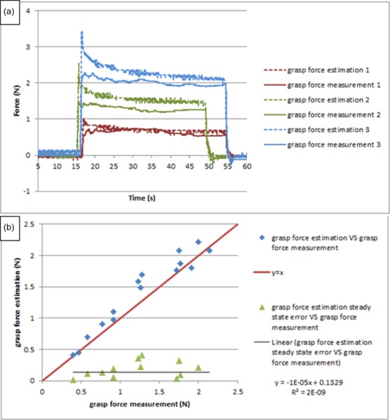
Figure 18 shows the force estimation performance for long-duration steady input on the grasp DOF. Due to the friction introduced in the joints, force estimation is linearly proportional to the force measurement, with a ratio of 1.5849. To compensate for the effect of friction, a calibration coefficient of 1/1.5849 is applied to all the force estimation data, and the calibrated result is shown in Fig. 19. It is noticed that the force estimation is slightly larger than the force measurement, and the error is distributed around an average value of 0.1329 N. The repeated results demonstrate the reliability of this method. The dynamic peak at the beginning of every force estimation still remains; however, it is very brief (only lasting around 0.2 s), which is at the frequency transition between slow-acting (pressure, force) and fast-acting (vibration) mechanoreceptors in human skin [23,24]. Therefore, the surgeon is expected to be able to distinguish this dynamic peak from the real force estimation in a practical scenario.
Fig. 18.
The force estimation fit before calibration on grasp DOF
Fig. 19.
The calibrated result for long input on grasp DOF
Figure 20 shows the force estimation performance for short-time duration steady input after calibration. It is noticed that the force estimation is slightly larger than the force measurement; due to the dynamic effect, the error is larger than that for long-duration input, and is around 0.4312 N. Also, after applying calibration, the error is no longer linearly increasing with load (as in Fig. 13).
Fig. 20.
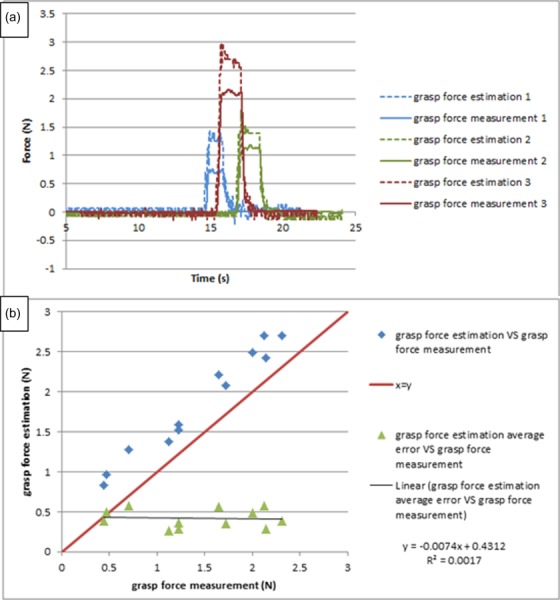
The calibrated result for short input on grasp DOF
Figure 21 shows the force estimation performance for high-frequency periodic input after calibration. It shows that this force estimation method can respond quickly enough for general surgical motions. Due to the smaller size, the force estimation is 30 ms ahead of the force measurement; this makes sense since the motor actuation always leads the force sensor being pressed. Also, compared with Fig. 15(b), the force estimation in Fig. 21(b) has more peaks, which shows an instability tendency. The reason is that the motion velocity is twice as high for this actual sized prototype compared to the test for the scaled prototype (0.5 rad/s); the higher velocity and acceleration of motors causes the current to change quickly, thus leading to the instability tendency of the force estimation. Literature shows that 0.5 rad/s can meet the design requirement [25], so this instability tendency should not pose a real problem in practical scenarios.
Fig. 21.
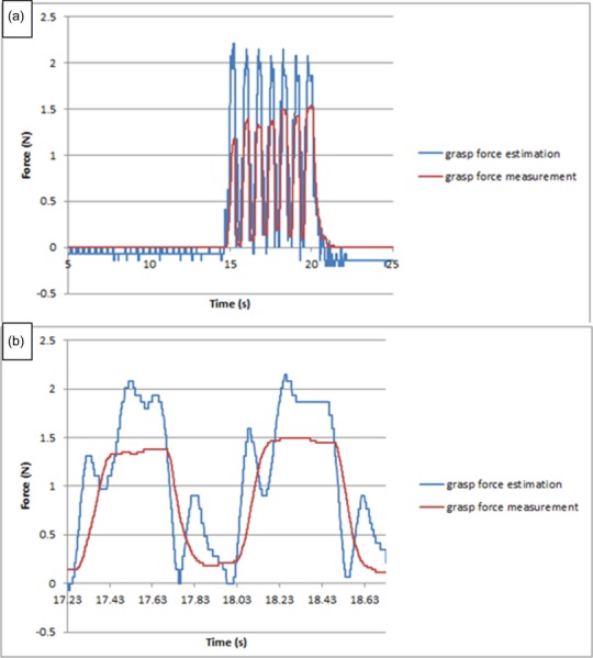
The calibrated result for periodic input on grasp DOF
Performance characteristics on the pitch and yaw DOFs are similar. Tables 3 and 4 compare the estimation error and time delay on the three DOFs.
4. Preliminary Haptic Tests
The existing robotic surgical system (da Vinci Surgical System) for minimally invasive surgery does not have haptic features; we believe with the technique described in this paper, a haptic interface can be added to it without violating sterilization requirements. To demonstrate this idea, three preliminary haptic tests have been implemented.
The first test is for stiffness differentiation. Using wood, foam, and sponge blocks with similar shape and size, each is grabbed separately with the grasper prototype, and the grasp jaw angle and grasp force estimation are recorded and displayed in Fig. 22. Although the force estimation is noisy (because the force estimation is based on motor current, which is sensitive to motion), it clearly shows the difference of stiffness between the three materials.
Fig. 22.
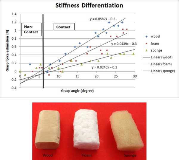
Stiffness differentiation
The second test is for grasp force control. Figure 23(a) shows the setup; the grasper is in position control mode, with an animal tissue between the jaws. The operator adjusts the grasp angle to get a grasp force close to 1 N (Fig. 23(b)). This test demonstrates that, with the force estimation technique (even when presented visually and not as tactile feedback), surgeons can perceive the tool–tissue interaction force in real time and adjust their operations to avoid tissue damage during surgery.
Fig. 23.
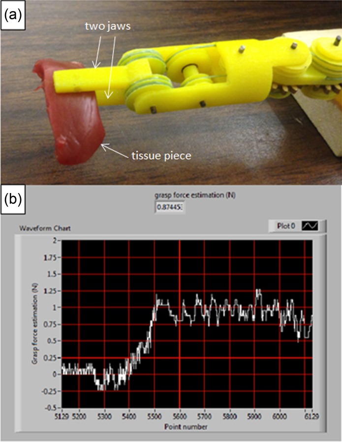
Grasp force control (* every grid line on the x axis represents four seconds)
The third test is for tumor detection. Figure 24 shows a piece of animal tissue with uniform thickness, and a stiff plastic part is embedded to simulate a tumor. Grasping the tissue at different locations with same amount of tissue strain (around 20 deg change in grasp angle from initial contact), it is found that the grasp force is higher at the tumor location (0.85 N versus 0.5 N), as shown in Fig. 25. This test shows that, with the help of force feedback, the surgeon can do basic tissue palpation without sensors, thus improving surgical capabilities.
Fig. 24.
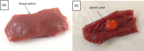
Animal tissue with tumor embedded
Fig. 25.
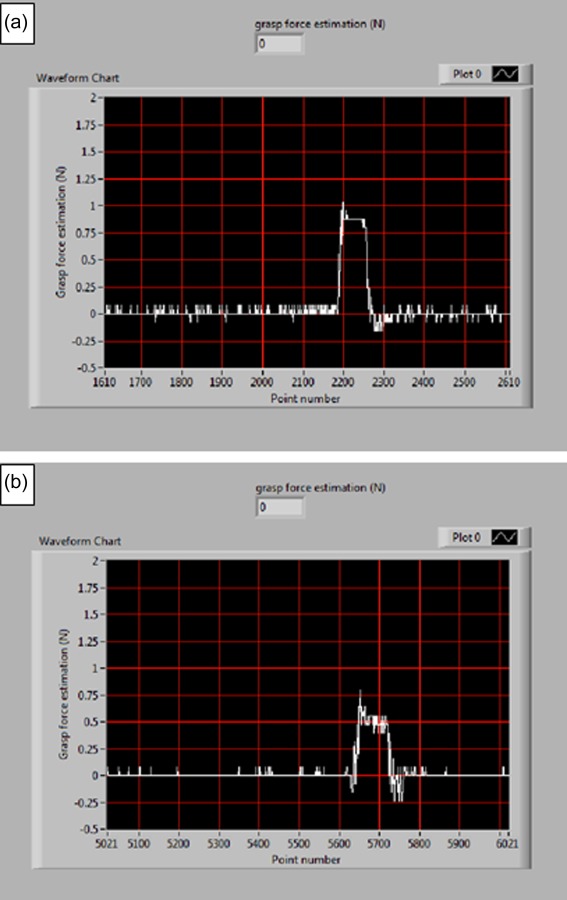
Grasp forces at locations (a) with tumor and (b) without tumor
5. Discussion and Conclusions
This paper describes a tool-tissue force estimation method for a 3-DOF robotic surgical grasper. The results show that this method can estimate the tool–tissue reaction forces on grasp, pitch, and yaw DOFs with acceptable accuracy and delay for purposes of force reflection to a master control. The greatest advantage of this method is that it requires no sensors, so the surgical tool can be totally composed of mechanical parts, compatible with existing sterilization technology.
There are still three remaining issues to be explored. First, the force estimation obtained from motor current includes the motor effort to compensate the operation force together with the mechanism dynamics, which causes the estimation error to be somewhat large. Although coarse force feedback can improve the performance of novice surgeons [26], we believe fine force feedback will serve the surgeon better; appropriate calibration or compensation is needed to eliminate the dynamic effects. Second, literature shows that in real surgeries up to 5 N reaction force is required in the direction perpendicular to the tool axis [27]; however, due to the insufficient strength of 3D printed components and the insufficient stiffness of the polymeric cable, the operation force tested to date is in the relatively smaller range, about 2 N; cast or machined metal components and stainless steel cable are needed to test larger forces. Third, the motor motion is controlled by a high-frequency pulse-width modulation (PWM) signal (20 kHz), and this causes the motor current to change rapidly. To obtain the average motor current, which is linearly proportional to the load, a low-pass filter with cutoff frequency 3 Hz is applied. This technique works well, as shown above, but it requires the motor vibrating all the time to dynamically adjust its current to carry the load (Fig. 26). Even though the motor is in a quasi-steady state, the small-amplitude vibration (±0.23 deg) may disturb the surgeon's operation and shorten the motor's life. Other techniques are needed to extract the average value from the noisy motor current signal.
Fig. 26.
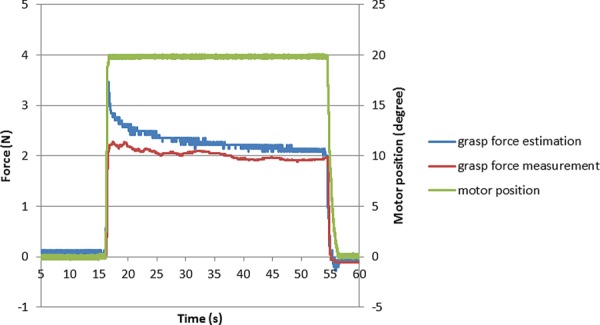
Motor vibration
It is expected that by applying this sensorless force estimation method, a haptic interface can be built which is compatible with existing surgical robots and surgical procedures, so that surgeons can sense tool–tissue reaction forces and increase surgical efficiency and efficacy.
Contributor Information
Baoliang Zhao, Department of Mechanical , and Materials Engineering, , University of Nebraska–Lincoln, , Lincoln, NE 68508 , e-mail: baoliang.zhao2@gmail.com.
Carl A. Nelson, Department of Mechanical , and Materials Engineering, , University of Nebraska–Lincoln, , Lincoln, NE 68508 , e-mail: cnelson5@unl.edu
References
- [1].Intuitive Surgical, 2014, “ Clinical Evidence,” Intuitive Surgical, Inc., Sunnyvale, CA, accessed June 10, 2014, http://www.davincisurgery.com/facts/.
- [2]. Okamura, A. M. , 2009, “ Haptic Feedback in Robot-Assisted Minimally Invasive Surgery,” Curr. Opin. Urol., 19(1), pp. 102–107. 10.1097/MOU.0b013e32831a478c [DOI] [PMC free article] [PubMed] [Google Scholar]
- [3]. Puangmali, P. , Althoefer, K. , Seneviratne, L. D. , Murphy, D. , and Dasgupta, P. , “ State-of-the-Art in Force and Tactile Sensing for Minimally Invasive Surgery,” IEEE Sens. J., 8(4), pp. 371–381. 10.1109/JSEN.2008.917481 [DOI] [Google Scholar]
- [4]. Fischer, G. S. , Akinbiyi, T. , Saha, S. , Zand, J. , Talamini, M. , Marohn, M. , and Taylor, R. , 2006, “ Ischemia and Force Sensing Surgical Instruments for Augmenting Available Surgeon Information,” 1st IEEE/RAS-EMBS International Conference on Biomedical Robotics and Biomechatronics (BioRob 2006), Pisa, Italy, Feb. 20–22, pp. 1030–1035. 10.1109/BIOROB.2006.1639227 [DOI] [Google Scholar]
- [5]. Hammond, F. L. , Smith, M. J. , and Wood, R. J. , 2014, “ Printing Strain Gauges on Surgical Instruments for Force Measurement,” ASME J. Med. Devices, 8(3), p. 030935. 10.1115/1.4027080 [DOI] [Google Scholar]
- [6]. Menciassi, A. , Eisinberg, A. , Carrozza, M. C. , and Dario, P. , 2003, “ Force Sensing Microinstrument for Measuring Tissue Properties and Pulse in Microsurgery,” IEEE/ASME Trans. Mechatron., 8(1), pp. 10–17. 10.1109/TMECH.2003.809153 [DOI] [Google Scholar]
- [7]. Gafford, G. B. , Kesner, S. , Wood, R. , and Walsh, C. , 2013, “ Force-Sensing Surgical Grasper Enabled by Pop-Up Book MEMS,” IEEE International Conference on Intelligent Robots and Systems (IROS), Tokyo, Nov. 3–7, pp. 2552–2558. 10.1109/IROS.2013.6696716 [DOI] [Google Scholar]
- [8]. Payne, C. , Tari, H. , Marcus, H. , and Yang, G. , 2014, “ Hand-Held Microsurgical Forceps with Force-Feedback for Micromanipulation,” IEEE International Conference on Robotics and Automation (ICRA), Hong Kong, May 31–June 7, pp. 284–289. 10.1109/ICRA.2014.6906623 [DOI] [Google Scholar]
- [9]. Sokhanvar, S. , Packirisamy, M. , and Dargahi, J. , 2007, “ A Multifunctional PVDF-Based Tactile Sensor for Minimally Invasive Surgery,” Smart Mater. Struct., 16(4), pp. 989–998. 10.1088/0964-1726/16/4/006 [DOI] [Google Scholar]
- [10]. Dargahi, J. , Parameswaran, M. , and Payandeh, S. , 2000, “ A Micromachined Piezoelectric Tactile Sensor for an Endoscopic Grasper-Theory, Fabrication and Experiments,” Microelectromech. Syst., 9(3), pp. 329–335. 10.1109/84.870059 [DOI] [Google Scholar]
- [11]. Ottermo, M. V. , Stavdahl, O. , and Johansen, T. A. , 2004, “ Palpation Instrument for Augmented Minimally Invasive Surgery,” IEEE/RSJ International Conference on Intelligent Robots and Systems (IROS 2004), Sendai, Japan, Sept. 28–Oct. 2, pp. 3960–3964. 10.1109/IROS.2004.1390033 [DOI] [Google Scholar]
- [12]. Seibold, U. , Kubler, B. , and Hirzinger, G. , 2005, “ Prototype of Instrument for Minimally Invasive Surgery With 6-Axis Force Sensing Capability,” IEEE International Conference on Robotics and Automation (ICRA 2005), Barcelona, Spain, Apr. 18–22, pp. 18–22. 10.1109/ROBOT.2005.1570167 [DOI] [Google Scholar]
- [13]. Kubler, B. , Seibold, U. , and Hirzinger, G. , 2005, “ Development of Actuated and Sensor Integrated Forceps for Minimally Invasive Robotic Surgery,” Int. J. Med. Rob. Comput. Assisted Surg., 1(3), pp. 96–107. 10.1002/rcs.33 [DOI] [PubMed] [Google Scholar]
- [14]. Mayer, H. , Gomez, F. , Wierstra, D. , Nagy, I. , Knoll, A. , and Schmidhuber, J. , 2006, “ A System for Robotic Heart Surgery That Learns to Tie Knots Using Recurrent Neural Networks,” IEEE/RSJ International Conference on Intelligent Robots and Systems (IROS), Beijing, Oct. 9–15, pp. 543–548. 10.1109/IROS.2006.282190 [DOI] [Google Scholar]
- [15]. Li, X. , 2001, “ Real-Time Prediction of Work Piece Errors for a CNC Turning Center, Part 3. Cutting Force Estimation Using Current Sensors,” Int. J. Adv. Manuf. Technol., 17(9), pp. 659–664. 10.1007/s001700170130 [DOI] [Google Scholar]
- [16]. Jeong, Y. H. , and Cho, D. W. , 2002, “ Estimating Cutting Force From Rotating and Stationary Feed Motor Currents on a Milling Machine,” Int. J. Mach. Tools Manuf., 42(14), pp. 1559–1566. 10.1016/S0890-6955(02)00082-2 [DOI] [Google Scholar]
- [17]. Tholey, G. , Pillarisetti, A. , Green, W. , and Desai, J. P. , 2004, “ Design, Development, and Testing of an Automated Laparoscopic Grasper With 3-D Force Measurement Capability,” International Symposium on Medical Simulation (ISMS 2004), Cambridge, MA, June 17–18, pp. 38–48. 10.1007/978-3-540-25968-8_5 [DOI] [Google Scholar]
- [18]. Zhao, B. , and Nelson, C. , 2013, “ Decoupled Cable-Driven Grasper Design Based on Planetary Gear Theory,” ASME J. Med. Device., 7(2), p. 020918. 10.1115/1.4024329 [DOI] [Google Scholar]
- [19]. Zhao, B. , and Nelson, C. , 2014, “ A Cable-Driven Grasper With Decoupled Motion and Forces,” ASME J. Med. Devices, 8(3), p. 030922. 10.1115/1.4027043 [DOI] [Google Scholar]
- [20]. Zhao, B. , and Nelson, C. , 2015, “ Sensorless Force Estimation for a 3-DOF Motorized Surgical Grasper,” ASME Design of Medical Devices Conference, Minneapolis, MN, Apr. 13–16, ASME Paper No. DMD 2015–8654. 10.1115/1.4030604 [DOI] [Google Scholar]
- [21]. Bhagat, N. A. , 2011, “ Sensing and Cancellation of Tremors in Surgeon's Hands During Microsurgery,” MS thesis, Indian Institute of Technology, Bombay. [Google Scholar]
- [22]. Sengul., A. , Rivest, F. , Elk, M. V. , Blanke, O. , and Bleuler, H. , 2013, “ Visual and Force Feedback Time-Delays Change Telepresence: Quantitative Evidence From Crossmodal Congruency Task,” World Haptics Conference (WHC), Daejeon, Korea, Apr. 14–17, pp. 577–582. 10.1109/WHC.2013.6548472 [DOI] [Google Scholar]
- [23]. Kuchenbecker, K. J. , and Culbertson, H. , 2014, “ Haptic Rendering of Textures,” 2014 IEEE Haptics Symposium, Houston, TX Feb. 23–26. [Google Scholar]
- [24]. Johansson, R. S. , and Flanagan, J. R. , 2009, “ Coding and Use of Tactile Signals from the Fingertips in Object Manipulation Tasks,” Nat. Rev. Neurosci. 10(5), pp. 345–359. 10.1038/nrn2621 [DOI] [PubMed] [Google Scholar]
- [25]. Lum, M. J. , Trimble, D. , and Rosen, J. , 2006, “ Multidisciplinary Approach for Developing a New Minimally Invasive Surgical Robotic System,” 1st IEEE/RAS-EMBS International Conference on Biomedical Robotics and Biomechatronics (BioRob 2006), Pisa, Italy, Feb. 20–22, pp. 841–846. 10.1109/BIOROB.2006.1639195 [DOI] [Google Scholar]
- [26]. Reiley, C. E. , Akinbiyi, T. , Burschka, D. , Chang, D. C. , Okamura, A. M. , and Yuh, D. D. , 2008, “ Effects of Visual Force Feedback on Robot-Assisted Surgical Task Performance,” J. Thoracic Cardiovasc. Surg., 135(1), pp. 196–202. 10.1016/j.jtcvs.2007.08.043 [DOI] [PMC free article] [PubMed] [Google Scholar]
- [27]. Markvicka, J. M. , 2014, “ Design and Development of a Miniature In Vivo Surgical Robot With Distributed Motor Control for Laparoscopic Single-Site Surgery,” MS thesis, University of Nebraska–Lincoln, Lincoln, NE. [Google Scholar]


