

Abstract
The mitral valve (MV) is a bileaflet valve positioned between the left atrium and ventricle of the heart. The annulus of the MV has been observed to undergo geometric changes during the cardiac cycle, transforming from a saddle D-shape during systole to a flat (and less eccentric) D-shape during diastole. Prosthetic MV devices, including heart valves and annuloplasty rings, are designed based on these two configurations, with the circular design of some prosthetic heart valves (PHVs) being an approximation of the less eccentric, flat D-shape. Characterizing the effects of these geometrical variations on the filling efficiency of the left ventricle (LV) is required to understand why the flat D-shaped annulus is observed in the native MV during diastole in addition to optimizing the design of prosthetic devices. We hypothesize that the D-shaped annulus reduces energy loss during ventricular filling. An experimental left heart simulator (LHS) consisting of a flexible-walled LV physical model was used to characterize the filling efficiency of the two mitral annular geometries. The strength of the dominant vortical structure formed and the energy dissipation rate (EDR) of the measured fields, during the diastolic period of the cardiac cycle, were used as metrics to quantify the filling efficiency. Our results indicated that the O-shaped annulus generates a stronger (25% relative to the D-shaped annulus) vortical structure than that of the D-shaped annulus. It was also found that the O-shaped annulus resulted in higher EDR values throughout the diastolic period of the cardiac cycle. The results support the hypothesis that a D-shaped mitral annulus reduces dissipative energy losses in ventricular filling during diastole and in turn suggests that a symmetric stent design does not provide lower filling efficiency than an equivalent asymmetric design.
Keywords: left ventricle filling, vortex flow, mitral annulus shape
1. Introduction
The MV is a complex anatomical structure in the human left heart that permits unidirectional flow from the left atrium to the LV during the diastolic phase of the cardiac cycle. The flow through the native mitral annulus and the two MV leaflets results in the generation of an inflow vortex ring within the LV, which has been investigated experimentally and computationally by several researchers [1–8]. Heart disease manifestations, such as dilated cardiomyopathy and diastolic dysfunction, have been shown to alter the inflow vortex ring characteristics [9,10] and mixing of blood within the LV [11,12]. An integrated mechanistic understanding of the role of individual anatomical structures in the MV complex, including the MV leaflets, mitral annulus, and the subvalvular apparatus, on the LV filling fluid dynamics is needed for optimizing the design of biomedical devices intended for use in the mitral position.
Two major types of medical devices developed for the MV complex include PHVs and annuloplasty rings. Several types of PHVs for the mitral position are currently available [13–15], the most common of which include bileaflet (“three-jet” orifice) and bioprosthetic (circular orifice) designs. Previous studies on PHVs intended for the mitral position have investigated the LV filling fluid mechanics using bileaflet, tilting disk, and monoleaflet designs [11,16,17], as well as using PHVs with asymmetric leaflet lengths as observed in the native MV [18–20]. However, most of the studies of LV fluid mechanics employing physical and computational models (excluding in vivo studies) are limited to using a circular mitral annulus as a fundamental assumption. It is important to note that physiological observations have shown that the mitral annulus continuously undergoes geometric deformation throughout diastole, resulting in alterations to the shape of the mitral annulus, position of the leaflets, and position of the mitral annulus plane relative to the apex of the LV [21]. Specifically, in vivo studies have shown that the annulus motion during diastole results in changing the MV annulus from a saddle D-shaped to a flat, less eccentric, D-shaped geometry [22–25]. This flat and less eccentric D-shape during diastole has been simplified to a circular design (O-shape) for most of the MV prosthetic devices used today. From a fluid mechanics standpoint, the intraventricular filling fluid dynamic differences that are observed between D- versus O-shaped annuli are not clear. It is also unclear what the effect of altering this annular shape to a circular design (O-shape) during diastolic filling might be. We hypothesize that the physiological geometric shape of the native MV annulus (D-shape) benefits LV filling via promoting the generation of a weaker mitral inflow vortex ring structure and consequently minimizing dissipative energy losses.
The practical relevance of the current study must be underscored in that PHVs for the mitral position with D-shaped annular geometry have been proposed recently [26]. This nontraditional mitral PHV design is based on the assumption that mimicking the unaltered native MV annulus would be optimal for restoring normal cardiac function. In addition, majority of mitral annuloplasty rings employ D-shaped annulus geometry [27–29]. Most annuloplasty rings used in present day clinical procedures are designed considering structural factors, such as leaflet stress distribution during annulus interaction with the time-varying motion of the left heart complex, and eventual surgical selection is made based on matching with patient-specific anatomy and ease of positioning. Though annuloplasty rings have historically been designed with primarily structural considerations, recent studies using different shapes of mitral prostheses have shown that the shape of the orifice can adversely impact the energetics of LV filling [4,20]. It is thus important to consider both the structural and fluid dynamic interactions of the MV complex with the LV while designing prosthetic devices. From an engineering standpoint, using an axisymmetric, O-shaped annulus in prosthetic MV devices allows for substantial design simplification, in sharp contrast to the complex three-dimensional morphology of the native mitral annulus. Specific to diastolic filling through these devices, it is unclear as to whether there is a functional advantage or compromise involved in adopting an O-shaped annulus design. To optimize the geometric design of prosthetic devices for implantation in the MV complex, it is imperative that the LV filling characteristics are investigated under varying mitral annulus shapes. A mechanistic study is thus required to identify the isolated effects of varying mitral annulus shape on the vortex formation process and efficiency of LV filling. Although the native MV annulus varies throughout diastole, this “static” approximation will provide very useful information on how the dynamic MV annulus affects filling fluid dynamics.
In this paper, we examine the fluid dynamic changes resulting from altering the mitral annulus from a D-shape to an O-shape during LV filling. An in vitro experimental LHS consisting of a flexible-walled LV physical model was used for the investigation. Two prototypes of MV annulus geometries, including a D- and an O-shaped annulus, were used to comparatively study the diastolic filling fluid characteristics using particle image velocimetry (PIV) under resting conditions of 70 beats per minute and normal/healthy hemodynamic conditions. The annulus models were designed to have the same geometric orifice area. To decouple the specific effects of the orifice shape from other valvular features, MV leaflets were not included in the prototype models used for this investigation. Sections 4–6 of the paper describe the experimental setup of the LV physical model and the mock circulatory loop, diagnostic methods used for the study, and a discussion of results comparing the flow field and vortical characteristics obtained using O-shaped and D-shaped mitral annulus models.
2. Materials and Methods
2.1. Left Heart Simulator
2.1.1. LV Design and Construction.
The design of the ventricle model used in this study was based on the anatomy of a healthy human volunteer. A series of concentric ellipses (Fig. 1(a)) were fit to five magnetic resonance short-axis slices of the LV geometry obtained during the peak systolic phase of the cardiac cycle. The aortomitral angle was fixed at 125 deg such that the mitral and aortic annular planes matched diastolic in vivo conditions [30]. This geometry was generated using Solidworks™ (Dassault Systèmes Solidworks Corporation, Waltham, MA) and was cast by Venair (Terrassa-Barcelona, Spain). A liquid silicone rubber polymer was chosen as the material to provide optical clarity for flow visualization and sufficient level of flexibility for pumping action. Further details of the material properties of the silicone rubber used to cast the ventricle are summarized in Table 1.
Fig. 1.
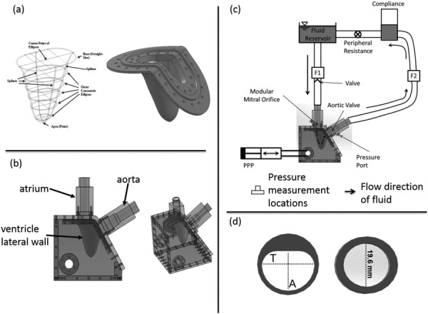
(a) Schematic of the ellipses fit to patient MRI scan and compliant ventricular geometry created out of liquid silicone. (b) LHS consisting of the flexible LV, atrial, and aortic sections. (c) Schematic of the in vitro LV flow circuit. Flow probes F1 and F2 are used to measure mitral and aortic flow rates, respectively. Pressures were measured in the ventricular and aortic positions. The flow direction through the LV model is indicated using a dashed arrow. PPP stands for programmable piston pump. (d) Mitral annular geometries used for the study. The O-shaped annulus had a diameter of 19.6 mm, while T = 22.10 mm and A = 16.76 mm for the D-annulus. Orifice areas were kept constant at 3.0 cm2.
Table 1.
Material properties of silicone used to construct LV
| Liquid silicone rubber properties | |
|---|---|
| Shore hardness | 40 A |
| Tensile strength (MPa) | 5.5 |
| Elongation (%) | 250 |
| Tear strength (kN/m) | 13.1 |
| Material thickness (cm) | 0.159 |
| Material color | Transparent |
2.1.2. System Setup.
Ventricular diastolic flow was simulated using an in vitro LHS as shown in Fig. 1(b). The LHS comprises of a reservoir mimicking the left atrium, rigid-walled aortic outflow section, and a flexible-walled LV physical model. Pulsatile pressure fluctuations were imposed in a fluid-filled chamber housing the LV physical model using a programmable piston pump (Superpump, Vivitro Systems, Victoria, BC). The pressure fluctuations resulted in the deformation of the LV model, driving flow through the mitral and aortic annuli, respectively. Physiologically observed hemodynamics (mitral inflow rate and aortic pressure) was obtained by adjusting systemic resistance and compliance elements included in the flow circuit (Fig. 1(c)). More information on this system can be found in our previous work [31].
A bileaflet mechanical heart valve (BMHV) was used in the aortic position. For the mitral annulus, two custom built annuli (Fig. 1(d)) were used individually. A second BMHV was placed ten-inlet pipe diameters of the mitral annulus to ensure unidirectional flow in the absence of mitral leaflets and their corresponding subvalvular apparatus. The cross-sectional geometry of the annulus matches the geometry of the inlet tube up to 6.5d (d = diameter of the circular annulus = 19.6 mm) upstream of the annulus. At 6.5d, the tubing cross-sectional geometry changes to a circular geometry (diameter of 25.4 mm, area = 5.0671 cm2) for both the annuluses via a step change (from 25.4 mm to 19.6 mm).
The housing for the ventricle and all the chambers were constructed from optically clear acrylic (refractive index of 1.49) to allow for optical access for fluid visualization in the system. To mimic the kinematic viscosity of blood at 37 °C (3.5 cS), a 36% by volume glycerin solution in water was used as the fluid medium. The refractive index of the solution was 1.38. The outer chamber of the LHS housing the ventricle was also filled with the same fluid medium. Ventricular and aortic absolute pressures were measured using strain gage, fluid-filled, pressure transducers (Utah Medical Products, Inc., Midvale, UT). Volumetric flow rates into and out of the ventricle were measured using ultrasonic flow probes (TS 410, Transonic Systems, Inc., Ithaca, NY) as indicated by F1 and F2 in Fig. 1(c). For this study, the system was tuned for physiologic hemodynamic conditions (120/80 mm Hg systemic pressure and 5 l/min average cardiac output at a heart rate of 70 beats/min).
2.1.3. Mitral Annulus Geometries.
Two mitral annular geometries (O-shaped and D-shaped) were used for this study (Fig. 1(d)). The D-shaped annulus and its dimensions were based on the nominal profile of a native MV [22,23,29,32]. For the D-shaped annulus, the flat portion was positioned such that it was proximal to the aorta, matching anatomical in vivo orientation. Leaflets of the MVs were not included in the design because this study was solely focused on the effect of the annulus geometry. The orifice areas of both geometries were equal (3.0 cm2).
2.2. PIV Instrumentation and Processing.
Planar PIV was used to quantitatively visualize the flow patterns through three long-axis planes of the ventricle. The three planes (Fig. 2(b)) consisted of the central plane cutting through the center of the mitral annulus, and two other planes, a parallel distance of d/2 from the central plane on both sides, where d was the diameter (19.6 mm) of the O-shaped mitral annulus. Figure 2(a) shows the schematic of the PIV setup. Neutrally buoyant fluorescent particles (PMMA with RhB dye, 1–20 μm, Dantec Dynamics, Skovlunde, Denmark) were then used to seed the fluid inside the ventricle. The illumination of the particles was achieved using a double-cavity Nd:YAG laser (New Wave laser, 532 nm, ESI, Inc., Portland OR) with a pulse energy of 50 mJ. The resulting beam diameter was about 1 mm with a pulse width of 5 ns. A set of beam steering optics was used to deliver the beam to the measurement location. Light-sheet optics was then used to generate a sheet of about 1 mm thickness. Imaging of the particles was performed using a PIV CCD camera (LaVision, Germany, Imager Pro, 1600 × 1200 pixels) fitted with a Nikon Micro-Nikkor 60 mm focal length lens and a 62 mm diameter orange filter. The aperture of the lens was set at f/4. The characteristic cut-off wavelength of the orange filter used was 550 nm.
Fig. 2.
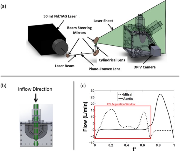
(a) Digital PIV setup with camera, laser, and optics, on the LV physical model. A cylindrical lens was used to convert the laser beam into a light sheet. (b) Planes of data acquisition. The central plane (center of the mitral annulus) was acquired along with two other planes at a distance of d/2 on either side of the central plane, where d (19.6 mm) is the diameter of the O-annulus. (c) Mitral inflow curve also depicting time points where PIV images were acquired. The peak E-wave was 16.5 l/min and A-wave was 13.75 l/min, giving an E/A ratio of 1.2. The flow curves were averaged over 15 cardiac cycles. The x-axis variable, t*, is the time T normalized by the cardiac cycle duration (856 ms).
PIV data were acquired over 200 cycles to compute phase averages for each measurement/acquisition. In addition, 31 phase-locked time points each spaced by approximately 25 ms were acquired during each cycle. The time spacing (dt: 800–1200 μs) between image pairs was optimized for all time points in the diastolic period of the cardiac cycle in order to capture velocity vectors (particle displacement 5–8 pixels). The particle size in the camera image ranged between 1.74 and 2.94 pixels.
DaVis (LaVision GmbH, Goettingen, Germany) was used to pre- and postprocess the PIV data. A sliding background subtraction of a scale length of 5 pixels was initially used to preprocess the raw images. Using a dual-pass interrogation with decreasing window size (64 × 64 to 32 × 32 pixels; 50% overlap), particle cross correlation was performed on the images. The velocity vector resolution was ∼1 mm. Vectors were deleted if peak ratio, Q, was less than 1.2; interpolation was performed to fill up empty spaces. The data analysis carried out on the resulting vector field includes: velocity profiles extraction, out-of-plane vorticity, 2D kinetic energy per unit mass of velocity field, viscous EDR per unit volume, and the vortex circulation.
2.3. Accuracy Estimation.
The uncertainty in velocity measurements was computed using methods described in Raffel et al. [33]. Bias error was determined by plotting the probability density histograms of the instantaneous velocity data. Peak-locking bias error () due to subpixel interpolation was of the order of an eighth of a pixel resulting in an uncertainty in velocity between 0.007 m/s and 0.01 m/s. The lag error was estimated by considering the relaxation time of the seed particles (10 μm) to step changes in velocity. The characteristic time defined as the time available for the seed particle to respond to rapid changes in the flow was an order of magnitude greater than the relaxation time. This indicated that the uncertainty of velocity measurement due to particle lag error was insignificant. The random error was computed using the following equation:
| (1) |
where is the random error, is the particle image diameter, and is the empirical constant that usually lies between 0.05 and 0.10. Thus for these set of experiments, the random error ranged from 0.087 pixels (0.05 × 1.74) to 0.294 (0.1 × 2.94) pixels. This resulted in a velocity measurement uncertainty between 0.003 m/s and 0.017 m/s.
The total measurement error is then computed by the below equation
| (2) |
where for a confidence interval of 95%. This results in a total measurement uncertainty between 0.015 m/s and 0.039 m/s which amounts to an uncertainty of 1.25–3.25% based on the maximum jet velocity of 1.2 m/s.
2.4. Definition of Calculated Quantities
2.4.1. Relative Jet Width.
The jet width can be related to how the inflow from the left atrium spreads in the LV. This affects mixing and stasis of fluid in the LV. More jet width could result in incoming jet spreading across a larger region of the LV and this could result in increased mixing and decreased blood stasis.
The relative width of the inflow jet was extracted from the velocity profiles based on the relation developed by White [34]. The boundary of the jet was defined as 1% of the maximum velocity along the line where each velocity profile was extracted (refer to Fig. 4). The spreading of the jet was then calculated by taking ratio of the widths of the jet at different spatial locations.
Fig. 4.
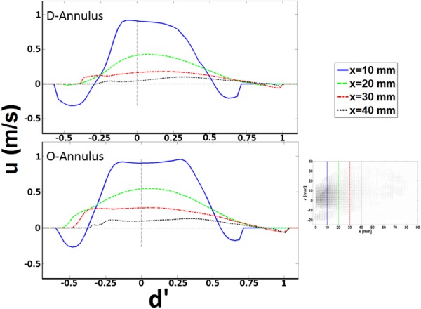
Velocity profiles at the center plane at select locations during peak E-wave for D- and O-annulus. d′ is the diameter = 2r normalized by the hydraulic diameter (dH = 4A/P, where A is the cross-sectional area and P is the wetted perimeter) of each annulus, respectively. u is the component of velocity in the x-direction.
2.4.2. Vortex Identification and Strength.
In order to identify the mitral inflow vortex structures, the swirling strength criterion (λci), which examines the imaginary part of the complex eigenvalues of the velocity gradient tensor, , was used with a 4.2% threshold of the local maximum value [35,36]. This relationship is defined for a two-dimensional flow field as shown in the following equation
| (3) |
The strength of the vortex proximal to the aorta was characterized by computing the circulation around it by evaluating Stokes theorem numerically as shown in the below equation
| (4) |
where is the out-of-plane vorticity, and A is a closed contour manually chosen such that it surrounded the vortical structure observed from the swirling strength criterion.
Circulation provides a large-scale characteristic of fluid rotation within a confined domain, such as the LV. A weaker vortex ring will produce lower circulation compared to a stronger vortex ring. Larger LV filling vortex circulation can increase energy dissipation losses.
2.4.3. Field Kinetic Energy.
The kinetic energy per unit mass of the flow field was calculated using the following equation:
| (5) |
where A is the area of the PIV field of view.
2.4.4. EDR.
The viscous EDR per unit volume was calculated using the below equation
| (6) |
where is the fluid dynamic viscosity, and u and v are the phase-averaged velocity components in the x- and y-directions, respectively.
Both EDR and KE can be related to LV work. Increasing EDR is indicative of increased LV mechanical workload to obtain normal ejection fraction, while increasing KE is indicative of decreasing ventricular workload.
3. Results
3.1. Intraventricular Flow Features.
This study focused solely on flow through the MV annulus, therefore, only the diastolic phase of the cardiac cycle was considered. The time duration of diastole was set at 65% of the cardiac cycle to match physiological conditions [37]. At a heart rate of 70 bpm and a stroke volume of 70 ml/cycle, the peak inflow Reynolds number for the E-wave and A-wave was calculated to be 4905 and 4188, respectively. Figure 3 illustrates the two-dimensional, phase-averaged velocity vector field overlaid on isovorticity contour map for the D- (left column) and O-shaped annulus (right column), respectively, at the center plane. Four phases in diastole are shown: Peak (a − 0.23), mid-deceleration (b − 0.29), and end (c − 0.35) of E-wave as well as the peak of the A-wave (d − 0.61).
Fig. 3.
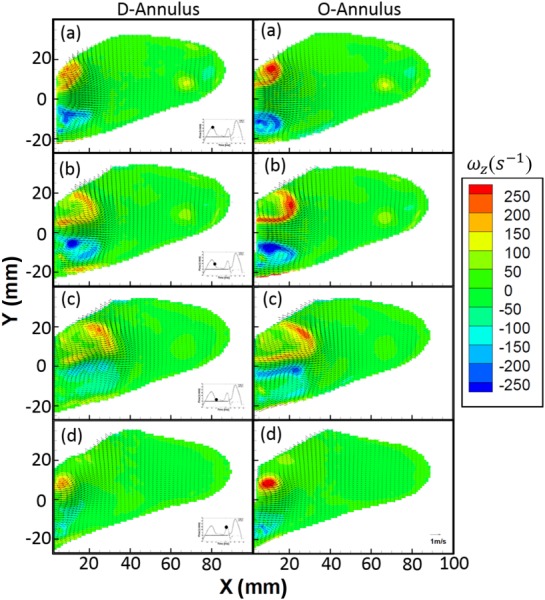
Center plane isovorticity contours overlaid with velocity vectors at select time points((a) peak of E-wave, 0.23; (b) deceleration of E-wave, 0.29; (c) end of E-wave, 0.35; and (d) peak of A-wave, 0.61) during the diastolic period of cardiac cycle for both the D (left column) and the O (right column) shaped mitral annulus
The general bulk flow features observed for both annuli are qualitatively similar and agree with other previously published work [16,17,38,39]. The unsteady flow through the mitral annulus results in the formation of a counter-rotating vortex pair in the 2D flow field with a trailing jet. Due to its proximity to the lateral wall (see Fig. 1(b)) of the LV, the negative-signed vortex of the pair interacts with the wall boundary, causing it to move slower than the positive-signed vortex, thereby leading to asymmetry about the centerline of the inflow jet. This phenomenon has also been observed previously by Pierrakos and Vlachos [4] and Vukićević et al. [20]. The maximum velocity at peak E-wave for the D- and O-shaped annulus was measured to be 1.15 and 1.20 m/s, respectively. From the velocity field plots during the E-wave, it was observed that the width of the jet for the D-annulus was smaller than that of the O-annulus, which is due to a difference in the planar diameter of both annular geometries. From the velocity profiles (Fig. 4), we observed that for the E-wave jet in both annuli, the location of maximum velocity shifted in position on moving downstream of the valve toward the apex of the ventricle. The general preference of the jet was to move away from being centerline symmetric and gradually skewed away from the lateral wall and toward the aorta. It was also observed that the relative spreading (Fig. 4, from X = 10–40 mm) of the jet (axial direction) increases with axial distance away from the annulus, more so in the D-annulus (35% greater) than the O-annulus. Finally, at the center plane, the counterclockwise vortex proximal to the aorta that is formed during E-wave inflow has a 24% higher maximum intensity for the O-annulus (∼250 s−1) when compared to the D (∼190 s−1). The clockwise vortex structure formed proximal to the lateral wall breaks down earlier for the D-annulus.
3.2. Kinetic Energy.
The 2D kinetic energy per unit mass over the measured velocity field, EK, for each annulus was calculated at all the measurement planes and time points and plotted versus the normalized time. Figure 5 illustrates that the integrated 2D kinetic energy per unit mass over the measured plane inside the ventricle was similar for the D- and O-annulus. The maximum kinetic energy per unit mass for the O- and D-annulus, at the center plane, was determined to be approximately 12.5 m2 s−2, occurring during the E-wave. The similarity in magnitude was expected as the inflow prescribed through both annulus models with same geometric orifice area was the same. The maximum kinetic energy per unit mass at off-center planes was approximately 40% of the center plane. The time point at which the maximum kinetic energy per unit mass occurred was t* = 0.37, approximately 117 ms after peak E-wave, where t* is the time normalized by the cardiac cycle period, T (856 ms). The EK values for both annuli were observed to be similar across the diastolic period of the cardiac cycle.
Fig. 5.
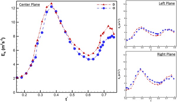
Two-dimensional kinetic energy per unit mass for center, left, and right planes. The x-axis variable, t*, is the time T normalized by the cardiac cycle duration (856 ms). For the center plane, the x-axis begins at t* = 0.15 because it was at this time that EK started to increase due to the effect of mitral inflow. For the left and right plane, EK begins at t* = 0.2 because at this time, the side walls of the ventricle were not in the same plane as the PIV acquisition plane. This phenomenon is also seen in Fig. 6.
3.3. Vortex Circulation.
The circulation of the counterclockwise vortex proximal to the aorta generated by the E-wave was calculated for all the measured time points at which it could be identified using the λci criterion. The vortex generated by the A-wave was neglected for this calculated parameter due to the complexities that arise from the interaction between the two vortical structures formed by the E and A waves. Such complex fluid interaction made it increasingly difficult to use the swirling strength criterion consistently to identify tightly packed vortex cores. For the left and right planes, the vortex could be clearly identified starting at t* = 0.18. At this time point, the ventricle side walls had expanded to a sufficient distance from the measurement plane. Figure 6 represents the circulation (Γ) as a function of normalized time. The center plane for both the D and O annular geometries had the largest strength (D: 32 m2 s−1 and O: 42.5 m2 s−1) occurring at t* = 0.27 and 0.30, respectively. The maximum circulation for the left and right planes was found to be approximately 55% of that at the center. The most important observation from this calculation was the fact that the strength of the vortex generated by O-shaped annulus was stronger than that generated by the D-annulus for 55% of the diastolic filling time period (center, 32.8%; left, 47.4%; and right, 47.1%).
Fig. 6.
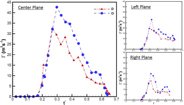
Circulation of vortex proximal to the aorta throughout diastole at the center, left, and right planes. The x-axis variable, t*, is the time T normalized by the cardiac cycle duration (856 ms).
3.4. EDR.
In order to quantify the viscous energy losses arising due to the mitral annular geometry, the EDR was calculated at all measured planes and time points. As can been seen in Fig. 7, at the center plane, the O-shaped annulus was found to be consistently higher than the D-shaped. This difference was observed during both the E and A wave portions of diastole. The peak value for EDR of the O-shaped annulus was 38% greater than the corresponding value for D-shaped annulus. At the left and right planes, this difference was not as pronounced, with both annuli having similar EDR values across the diastolic phase of the cardiac cycle.
Fig. 7.
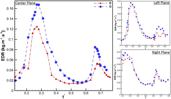
EDR per unit volume for all the three measured planes, through the diastolic period of the cardiac cycle
4. Discussion
The transition of the mitral annulus from a saddle D-shape during the systolic period of the cardiac cycle to a flat D-shape during diastole is well documented in clinical observations and experimental literature. The mitral annulus changes shape due to a combination of myocardial contraction and systolic expansion or contraction of the aortic root. During a diseased state, the annulus loses its shape due to myocardial remodeling, which leads to less ejection, less aortic expansion, and less shape change throughout the cardiac cycle [22–24,28,32,40].
A considerable number of experimental studies using LV physical models [1,4,20,41] have commonly used MV prostheses with circular annulus geometries to study intraventricular filling patterns. This study represents the first one to address the effect of the mitral annulus change in geometry on the left ventricular filling process and efficiency. Previous work by Vukićević et al. [20] studied the effect of both the mitral annulus geometry and the asymmetric MV leaflets; however, this study did not address the independent effects of the annulus shape from the effects of the asymmetric leaflets.
The link between the fluid mechanics downstream of the MV to ventricular energetics was proposed by Pierrakos and Vlachos [4]. They observed that the filling efficiency of the LV is inversely proportional to the circulation of the vortex ring generated during the filling process. In the present work, we investigate the changes in LV filling fluid dynamics between O-shaped and D-shaped mitral annuli. Our experimental analyses demonstrate that the D-shaped annulus is energetically favorable because of its ability to minimize dissipative losses during ventricular filling.
Comparing the two mitral annuli geometries, similar flow features were observed, which qualitatively resemble other previously published data on intraventricular flow, both in vitro and in vivo [1,6,7,42,43]. Two counter-rotating vortices form during inflow with the vortex closest to the lateral wall quickly dissipating. The vorticity magnitude of the vortex proximal to the aorta was 24% higher for the O-shaped annulus than for the D. This was the case for both the E and A waves. Considering the mitral annulus geometries alone, with the areas kept constant, one would not expect there to be such a difference in vorticity magnitudes, especially since the same piston motion profile was used for both cases. We believe that these differences in vorticity magnitudes are most likely due to the fact that the vortex formed from the D-shaped annulus is a more asymmetric ring, arising due to the interaction between the flat and curved edges, while that formed from O-shaped annulus is more axisymmetric and hence stronger [18,44,45]. This curvature would allow the smoother, more circular, annulus to result in an initially more symmetrical, ringlike vortex, which would be stronger. The velocity profiles (Fig. 4) show that the spreading of the inflow jet is greater for the D-annulus than the O. It is well known that the spreading of a jet is inversely proportional to momentum transfer of that jet [34]. From this relation, the momentum of the jet from the O-shaped annulus would be expected to be greater than that of the D-annulus. However, it must be noted that the measurements gathered in this study are two-dimensional representations of a highly three-dimensional flow field and hence do not capture the complete nature of the three-dimensional inflow jet.
To support the observations noted above, the circulation of the vortex proximal to the aorta and the kinetic energy per unit mass of the measured planes were calculated as functions of time. The maximum kinetic energy per unit mass computed for each measured plane was found to be similar in magnitudes across all planes between the D- and O-shaped annulus. Marginal differences in the planar maximum kinetic energy per unit mass were observed between annuli due to the fact that the jet entrance local diameter was slightly different between the D- and O-shaped annulus at each plane. As shown in Fig. 6, at the center plane, the peak circulation we calculated for the O-shaped annulus was 25% greater than the corresponding maximum value for the D-shaped annulus. This same trend was observed at the right and the left planes. Based on the correlation between circulation and filling efficiency [4], we can conclude from our circulation computations that the D-shaped annulus is better than the O-shaped annulus with regards to filling efficiency. It must, however, be noted that the correlation between circulation and filling efficiency was based on empirical observations alone. To further strengthen this conclusion, the EDR was calculated for all measured planes across diastole. The spatially integrated EDR plotted in time shows that the circular annulus results in larger viscous losses, with a maximum difference of approximately 38%, occurring during the E-wave, when compared to the D-shaped annulus. Similar trends observed during the E-wave portion of diastole were also observed during the A-wave. As a matter of fact, the EDR for the O-shaped annulus was approximately 70% greater than that of the D at the center plane. Similar trends were observed at the right and the left planes, though the differences observed were not at pronounced.
From an engineering perspective, it is simpler to design an axisymmetric stent for a mitral annulus prosthesis, compared to the intricate three-dimensional morphology of the native mitral annulus. This study provides evidence that this simplification to a circular geometry is not optimal for ventricular filling. It should be noted that the findings in this work are merely in the preliminary stages and are premature to make any definitive conclusions that affect the current design methods for MV prosthetic devices.
5. Limitations
While the bulk hemodynamic environment of the LV was simulated in this study, several limitations have to be noted. First, the native mitral annulus has a three-dimensional saddle shape while those used in this experiment were a 2D projection of the 3D shape. However, previous in vivo studies have noted that the saddle shape is predominantly during the systolic phase of the cardiac cycle and that during diastole, the shape is relatively flat [25,46,47]. Second, rigid geometries were selected for this study to more closely simulate existing prosthetic devices (most of which use rigid stents). This feature inherently limits the accuracy in replicating the compliant, time-varying geometry of the native mitral annulus. Future studies should take this into account. Third, the mock atrium used in this study does not capture the “funneling effect” of flow into the ventricle as observed in vivo; however, the results presented here are comparative and thus still provide insight regarding the differences between the D- and O-shaped mitral annulus. Finally, 2D components of a highly 3D flow field were captured and analyzed in this study. This does not account for the out-of-plane components, which play an important role in ventricular flow and should be considered in future studies.
6. Conclusions
By decoupling the effects of the mitral annulus and leaflet geometry, it was possible, for the first time, to provide a fluid mechanics insight of the effect of the mitral annulus shape on ventricular filling. We have provided quantitative data to demonstrate that the native shape of the mitral annulus is energetically favorable with regards to ventricular filling efficiency. The energetics calculations demonstrated that although the 2D kinetic energy per unit mass inside the LV was similar for both annular geometries, the EDR was higher for the O-annulus. Furthermore, the circulation of the dominant vortex formed was much higher for the O-annulus than for the D-annulus and based on the relationship established by Pierrakos and Vlachos [4], it can be concluded that the D-shaped annulus is energetically favorable. The EDR analysis confirmed that the O-shaped annulus lost more energy compared to the D-shaped annulus. These results support the hypothesis by demonstrating that the D-shaped annulus allows for a more efficient LV filling by minimizing energy dissipation within the LV. Furthermore, this study also provides insight on the design optimization of MV prosthetic devices by demonstrating that the commonly used design simplification of O-shaped annulus could be detrimental to the fluid dynamics of ventricular filling. Future studies on animal models would be required to verify our study findings in vivo and provide guidelines for improving design of mitral prostheses and annuloplasty rings based on LV filling fluid dynamics.
Acknowledgment
This study was funded by a grant from the National Heart, Lung and Blood Institute (RO1HL07262) and also partially funded by a Greater Southeast Affiliate Postdoctoral Fellowship Award to Arvind Santhanakrishnan (12POST12050522) from the American Heart Association. The authors would also like to thank Eric L. Pierce for his valuable insights, Venair (Terrassa-Barcelona, Spain) for casting the silicone ventricle, the machine shop personnel at the School of Chemical and Biomolecular Engineering at Georgia Tech for machining the left heart simulator, and finally Procter & Gamble for providing the glycerin used in this study.
Contributor Information
Ikechukwu U. Okafor, School of Chemical and , Biomolecular Engineering, , Georgia Institute of Technology, , 311 Ferst Drive NW, , Atlanta, GA 30332-0100 , e-mail: iokafor3@gatech.edu
Arvind Santhanakrishnan, Wallace H. Coulter Department of , Biomedical Engineering, , Georgia Institute of Technology , and Emory University, , Atlanta, GA 30313-2412;; School of Mechanical and , Aerospace Engineering, , Oklahoma State University, , 218 Engineering North, , Stillwater, OK 74078-5016 , e-mail: askrish@okstate.edu
Vrishank S. Raghav, Wallace H. Coulter Department of , Biomedical Engineering, , Georgia Institute of Technology , and Emory University, , Atlanta, GA 30313-2412 , e-mail: vrishank@gatech.edu
Ajit P. Yoganathan, School of Chemical and , Biomolecular Engineering, , Georgia Institute of Technology, , 311 Ferst Drive NW, , Atlanta, GA 30332-0100;; Wallace H. Coulter Department of , Biomedical Engineering, , Georgia Institute of Technology , and Emory University, , Technology Enterprise Park, , Suite 200, 387 Technology Circle, , Atlanta, GA 30313-2412 , e-mail: ajit.yoganathan@bme.gatech.edu
References
- [1]. Cenedese, A. , Del Prete, Z. , Miozzi, M. , and Querzoli, G. , 2005, “ A Laboratory Investigation of the Flow in the Left Ventricle of a Human Heart With Prosthetic, Tilting-Disk Valves,” Exp. Fluids, 39(2), pp. 322–335. 10.1007/s00348-005-1006-4 [DOI] [Google Scholar]
- [2]. Gharib, M. , Rambod, E. , Kheradvar, A. , Sahn, D. J. , and Dabiri, J. O. , 2006, “ Optimal Vortex Formation as an Index of Cardiac Health,” Proc. Natl. Acad. Sci. U. S. A., 103(16), pp. 6305–6308. 10.1073/pnas.0600520103 [DOI] [PMC free article] [PubMed] [Google Scholar]
- [3]. Krittian, S. , Schenkel, T. , Janoske, U. , and Oertel, H. , 2010, “ Partitioned Fluid-Solid Coupling for Cardiovascular Blood Flow: Validation Study of Pressure-Driven Fluid-Domain Deformation,” Ann. Biomed. Eng., 38(8), pp. 2676–2689. 10.1007/s10439-010-0024-4 [DOI] [PubMed] [Google Scholar]
- [4]. Pierrakos, O. , and Vlachos, P. P. , 2006, “ The Effect of Vortex Formation on Left Ventricular Filling and Mitral Valve Efficiency,” ASME J. Biomech. Eng., 128(4), pp. 527–539. 10.1115/1.2205863 [DOI] [PubMed] [Google Scholar]
- [5]. Pedrizzetti, G. , and Domenichini, F. , 2005, “ Nature Optimizes the Swirling Flow in the Human Left Ventricle,” Phys. Rev. Lett., 95(10), p. 108101. 10.1103/PhysRevLett.95.108101 [DOI] [PubMed] [Google Scholar]
- [6]. Domenichini, F. , Pedrizzetti, G. , and Baccani, B. , 2005, “ Three-Dimensional Filling Flow Into a Model Left Ventricle,” J. Fluid Mech., 539(1), pp. 179–198. 10.1017/S0022112005005550 [DOI] [Google Scholar]
- [7]. Le, T. B. , and Sotiropoulos, F. , 2012, “ On the Three-Dimensional Vortical Structure of Early Diastolic Flow in a Patient-Specific Left Ventricle,” Eur. J. Mech. B. Fluids, 35, pp. 20–24. 10.1016/j.euromechflu.2012.01.013 [DOI] [PMC free article] [PubMed] [Google Scholar]
- [8]. Seo, J. H. , and Mittal, R. , 2013, “ Effect of Diastolic Flow Patterns on the Function of the Left Ventricle,” Phys. Fluids, 25(11), p. 110801. 10.1063/1.4819067 [DOI] [Google Scholar]
- [9]. Eriksson, J. , Dyverfeldt, P. , Engvall, J. , Bolger, A. F. , Ebbers, T. , and Carlhäll, C. J. , 2011, “ Quantification of Presystolic Blood Flow Organization and Energetics in the Human Left Ventricle,” Am. J. Physiol. Heart Circ. Physiol., 300(6), pp. H2135–H2141. 10.1152/ajpheart.00993.2010 [DOI] [PubMed] [Google Scholar]
- [10]. Poh, K. K. , Lee, L. C. , Shen, L. , Chong, E. , Tan, Y. L. , Chai, P. , Yeo, T. C. , and Wood, M. J. , 2012, “ Left Ventricular Fluid Dynamics in Heart Failure: Echocardiographic Measurement and Utilities of Vortex Formation Time,” Eur. Heart J. Cardiovasc. Imaging, 13(5), pp. 385–393. 10.1093/ejechocard/jer288 [DOI] [PubMed] [Google Scholar]
- [11]. Choi, Y. J. , Vedula, V. , and Mittal, R. , 2014, “ Computational Study of the Dynamics of a Bileaflet Mechanical Heart Valve in the Mitral Position,” Ann. Biomed. Eng., 42(8), pp. 1668–1680. 10.1007/s10439-014-1018-4 [DOI] [PubMed] [Google Scholar]
- [12]. Zheng, X. , Seo, J. H. , Vedula, V. , Abraham, T. , and Mittal, R. , 2012, “ Computational Modeling and Analysis of Intracardiac Flows in Simple Models of the Left Ventricle,” Eur. J. Mech.: B/Fluids, 35, pp. 31–39. 10.1016/j.euromechflu.2012.03.002 [DOI] [Google Scholar]
- [13]. Pibarot, P. , and Dumesnil, J. G. , 2009, “ Prosthetic Heart Valves: Selection of the Optimal Prosthesis and Long-Term Management,” Circulation, 119(7), pp. 1034–1048. 10.1161/CIRCULATIONAHA.108.778886 [DOI] [PubMed] [Google Scholar]
- [14]. Dasi, L. P. , Pekkan, K. , de Zelicourt, D. , Sundareswaran, K. S. , Krishnankutty, R. , Delnido, P. J. , and Yoganathan, A. P. , 2009, “ Hemodynamic Energy Dissipation in the Cardiovascular System: Generalized Theoretical Analysis on Disease States,” Ann. Biomed. Eng., 37(4), pp. 661–673. 10.1007/s10439-009-9650-0 [DOI] [PMC free article] [PubMed] [Google Scholar]
- [15]. Sacks, M. S. , Schoen, F. J. , and Mayer, J. E. , 2009, “ Bioengineering Challenges for Heart Valve Tissue Engineering,” Annu. Rev. Biomed. Eng., 11(1), pp. 289–313. 10.1146/annurev-bioeng-061008-124903 [DOI] [PubMed] [Google Scholar]
- [16]. Pierrakos, O. , Vlachos, P. P. , and Telionis, D. P. , 2004, “ Time-Resolved DPIV Analysis of Vortex Dynamics in a Left Ventricular Model Through Bileaflet Mechanical and Porcine Heart Valve Prostheses,” ASME J. Biomech. Eng., 126(6), pp. 714–726. 10.1115/1.1824124 [DOI] [PubMed] [Google Scholar]
- [17]. Querzoli, G. , Fortini, S. , and Cenedese, A. , 2010, “ Effect of the Prosthetic Mitral Valve on Vortex Dynamics and Turbulence of the Left Ventricular Flow,” Phys. Fluids, 22(4), p. 041901. 10.1063/1.3371720 [DOI] [Google Scholar]
- [18]. Pedrizzetti, G. , and Domenichini, F. , 2006, “ Flow-Driven Opening of a Valvular Leaflet,” J. Fluid Mech., 569, pp. 321–330. 10.1017/S002211200600303X [DOI] [Google Scholar]
- [19]. Romano, G. P. , Querzoli, G. , and Falchi, M. , 2009, “ Investigation of Vortex Dynamics Downstream of Moving Leaflets Using Robust Image Velocimetry,” Exp. Fluids, 47(4–5), pp. 827–838. 10.1007/s00348-009-0727-1 [DOI] [Google Scholar]
- [20]. Vukićević, M. , Fortini, S. , Querzoli, G. , Espa, S. , and Pedrizzetti, G. , 2012, “ Experimental Study of an Asymmetric Heart Valve Prototype,” Eur. J. Mech.: B/Fluids, 35, pp. 54–60. 10.1016/j.euromechflu.2012.01.014 [DOI] [Google Scholar]
- [21]. Chan, J. K. , Merrifield, R. , Wage, R. R. , Symmonds, K. , Cannell, T. , Firmin, D. N. , Pepper, J. R. , Pennell, D. J. , and Kilner, P. J. , 2008, “ 2082 ‘Two-Dimensional M-Mode’ Display of the Mitral Valve From CMR Cine Acquisitions: Insights Into Normal Leaflet and Annular Motion,” J. Cardiovasc. Magn. Reson., 10(Suppl. 1), p. A351. 10.1186/1532-429X-10-S1-A351 [DOI] [Google Scholar]
- [22]. Ranganathan, N. , Lam, J. H. C. , Wigle, E. D. , and Silver, M. D. , 1970, “ Morphology of the Human Mitral Valve: II. The Valve Leaflets,” Circulation, 41(3), pp. 459–467. 10.1161/01.CIR.41.3.459 [DOI] [PubMed] [Google Scholar]
- [23]. Ormiston, J. A. , Shah, P. M. , Tei, C. , and Wong, M. , 1981, “ Size and Motion of the Mitral Valve Annulus in Man. I. A Two-Dimensional Echocardiographic Method and Findings in Normal Subjects,” Circulation, 64(1), pp. 113–120. 10.1161/01.CIR.64.1.113 [DOI] [PubMed] [Google Scholar]
- [24]. Timek, T. A. , and Miller, D. C. , 2001, “ Experimental and Clinical Assessment of Mitral Annular Area and Dynamics: What are We Actually Measuring?” Ann. Thorac. Surg., 72(3), pp. 966–974. 10.1016/S0003-4975(01)02702-3 [DOI] [PubMed] [Google Scholar]
- [25]. Rausch, M. K. , Bothe, W. , Kvitting, J.-P. E. , Swanson, J. C. , Ingels, N. B. , Miller, D. C. , and Kuhl, E. , 2011, “ Characterization of Mitral Valve Annular Dynamics in the Beating Heart,” Ann. Biomed. Eng., 39(6), pp. 1690–1702. 10.1007/s10439-011-0272-y [DOI] [PubMed] [Google Scholar]
- [26]. Banai, S. , Jolicoeur, E. M. , Schwartz, M. , Garceau, P. , Biner, S. , Tanguay, J.-F. , Cartier, R. , Verheye, S. , White, C. J. , and Edelman, E. , 2012, “ Tiara: A Novel Catheter-Based Mitral Valve Bioprosthesis: Initial Experiments and Short-Term Pre-Clinical Results,” J. Am. Coll. Cardiol., 60(15), pp. 1430–1431. 10.1016/j.jacc.2012.05.047 [DOI] [PMC free article] [PubMed] [Google Scholar]
- [27]. Jensen, M. O. , Jensen, H. , Smerup, M. , Levine, R. A. , Yoganathan, A. P. , Nygaard, H. , Hasenkam, J. M. , and Nielsen, S. L. , 2008, “ Saddle-Shaped Mitral Valve Annuloplasty Rings Experience Lower Forces Compared With Flat Rings,” Circulation, 118(Suppl. 14), pp. S250–S255. 10.1161/CIRCULATIONAHA.107.746776 [DOI] [PubMed] [Google Scholar]
- [28]. Daimon, M. , Fukuda, S. , Adams, D. H. , McCarthy, P. M. , Gillinov, A. M. , Carpentier, A. , Filsoufi, F. , Abascal, V. M. , Rigolin, V. H. , Salzberg, S. , Huskin, A. , Langenfeld, M. , and Shiota, T. , 2006, “ Mitral Valve Repair With Carpentier-McCarthy-Adams IMR ETlogix Annuloplasty Ring for Ischemic Mitral Regurgitation: Early Echocardiographic Results From a Multi-Center Study,” Circulation, 114(Suppl. 1), pp. I588–1593. 10.1161/CIRCULATIONAHA.105.001347 [DOI] [PubMed] [Google Scholar]
- [29]. Bothe, W. , Kvitting, J.-P. E. , Swanson, J. C. , Hartnett, S. , Ingels, N. B. , and Miller, D. C. , 2010, “ Effects of Different Annuloplasty Rings on Anterior Mitral Leaflet Dimensions,” J. Thorac. Cardiovasc. Surg., 139(5), pp. 1114–1122. 10.1016/j.jtcvs.2009.12.014 [DOI] [PMC free article] [PubMed] [Google Scholar]
- [30]. Veronesi, F. , Corsi, C. , Sugeng, L. , Mor-Avi, V. , Caiani, E. G. , Weinert, L. , Lamberti, C. , and Lang, R. M. , 2009, “ A Study of Functional Anatomy of Aortic-Mitral Valve Coupling Using 3D Matrix Transesophageal Echocardiography,” Circ. Cardiovasc. Imaging, 2(1), pp. 24–31. 10.1161/CIRCIMAGING.108.785907 [DOI] [PubMed] [Google Scholar]
- [31]. Okafor, I. U. , Santhanakrishnan, A. , Chaffins, B. D. , Mirabella, L. , Oshinski, J. N. , and Yoganathan, A. P. , 2015, “ Cardiovascular Magnetic Resonance Compatible Physical Model of the Left Ventricle for Multi-Modality Characterization of Wall Motion and Hemodynamics,” J. Cardiovasc. Magn. Reson., 17(1), p. 51. 10.1186/s12968-015-0154-9 [DOI] [PMC free article] [PubMed] [Google Scholar]
- [32]. Carpentier, A. , Adams, D. , and Filsoufi, F. , 2010, Valve Surgery, Saunders/Elsevier, Maryland Heights, MO. [Google Scholar]
- [33]. Raffel, M. , Willert, C. E. , Wereley, S. T. , and Kompenhans, J. , 2007, Particle Image Velocimetry, Springer, Berlin. [Google Scholar]
- [34]. White, F. M. , 2006, Viscous Fluid Flow, McGraw-Hill Higher Education, New York. [Google Scholar]
- [35]. Zhou, J. , Adrian, R. J. , Balachandar, S. , and Kendall, T. M. , 1999, “ Mechanisms for Generating Coherent Packets of Hairpin Vortices in Channel Flow,” J. Fluid Mech., 387, pp. 353–396. 10.1017/S002211209900467X [DOI] [Google Scholar]
- [36]. Adrian, R. J. , Christensen, K. T. , and Liu, Z. , 2000, “ Analysis and Interpretation of Instantaneous Turbulent Velocity Fields,” Exp. Fluids, 29(35), pp. 275–290. 10.1007/s003489900087 [DOI] [Google Scholar]
- [37]. Cui, W. , Roberson, D. A. , Chen, Z. , Madronero, L. F. , and Cuneo, B. F. , 2008, “ Systolic and Diastolic Time Intervals Measured From Doppler Tissue Imaging: Normal Values and Z-Score Tables, and Effects of Age, Heart Rate, and Body Surface Area,” J. Am. Soc. Echocardiogr., 21(4), pp. 361–370. 10.1016/j.echo.2007.05.034 [DOI] [PubMed] [Google Scholar]
- [38]. Pedrizzetti, G. , Domenichini, F. , and Tonti, G. , 2010, “ On the Left Ventricular Vortex Reversal After Mitral Valve Replacement,” Ann. Biomed. Eng., 38(3), pp. 769–773. 10.1007/s10439-010-9928-2 [DOI] [PubMed] [Google Scholar]
- [39]. Faludi, R. , Szulik, M. , D'hooge, J. , Herijgers, P. , Rademakers, F. , Pedrizzetti, G. , and Voigt, J.-U. , 2010, “ Left Ventricular Flow Patterns in Healthy Subjects and Patients With Prosthetic Mitral Valves: An In Vivo Study Using Echocardiographic Particle Image Velocimetry,” J. Thorac. Cardiovasc. Surg., 139(6), pp. 1501–1510. 10.1016/j.jtcvs.2009.07.060 [DOI] [PubMed] [Google Scholar]
- [40]. Siefert, A. W. , Jimenez, J. H. , Koomalsingh, K. J. , West, D. S. , Aguel, F. , Shuto, T. , Gorman, R. C. , Gorman, J. H. , and Yoganathan, A. P. , 2012, “ Dynamic Assessment of Mitral Annular Force Profile in an Ovine Model,” Ann. Thorac. Surg., 94(1), pp. 59–65. 10.1016/j.athoracsur.2012.02.074 [DOI] [PMC free article] [PubMed] [Google Scholar]
- [41]. Kheradvar, A. , and Gharib, M. , 2009, “ On Mitral Valve Dynamics and Its Connection to Early Diastolic Flow,” Ann. Biomed. Eng., 37(1), pp. 1–13. 10.1007/s10439-008-9588-7 [DOI] [PubMed] [Google Scholar]
- [42]. Bolger, A. F. , Heiberg, E. , Karlsson, M. , Wigstr, L. , Watt, W. , and Medicine, C. , 2007, “ Transit of Blood Flow Through the Human Left Ventricle Mapped by Cardiovascular Magnetic Resonance,” J. Cardiovasc. Magn. Reson., 9(5) pp. 741–747. 10.1080/10976640701544530 [DOI] [PubMed] [Google Scholar]
- [43]. Rodevand, O. , Bjornerheim, R. , Edvardsen, T. , Smiseth, O. A. , and Ihlen, H. , 1999, “ Diastolic Flow Pattern in the Normal Left Ventricle,” J. Am. Soc. Echocardiogr., 12(6), pp. 500–507. 10.1016/S0894-7317(99)70087-8 [DOI] [PubMed] [Google Scholar]
- [44]. Blondeaux, P. , and De Bernardinis, B. , 2006, “ On the Formation of Vortex Pairs Near Orifices,” J. Fluid Mech., 135(1983), pp. 111–122. [Google Scholar]
- [45]. Pedrizzetti, G. , 2010, “ Vortex Formation Out of Two-Dimensional Orifices,” J. Fluid Mech., 655, pp. 198–216. 10.1017/S0022112010000844 [DOI] [Google Scholar]
- [46]. Levine, R. A. , Triulzi, M. O. , Harrigan, P. , and Weyman, A. E. , 1987, “ The Relationship of Mitral Annular Shape to the Diagnosis of Mitral Valve Prolapse,” Circulation, 75(4), pp. 756–767. 10.1161/01.CIR.75.4.756 [DOI] [PubMed] [Google Scholar]
- [47]. Timek, T. A. , Glasson, J. R. , Lai, D. T. , Liang, D. , Daughters, G. T. , Ingels, N. B. , and Miller, D. C. , 2005, “ Annular Height-to-Commissural Width Ratio of Annulolasty Rings In Vivo,” Circulation, 112(Suppl. 9), pp. I423–I428. 10.1161/CIRCULATIONAHA.104.525485 [DOI] [PubMed] [Google Scholar]