

Optoelectronic electronic skins, or e-skins, introduce electronic sensing and displays on the surface of human skin.
Keywords: PLED, organic photo detector, pulse oximeter, flexible electronics
Abstract
Thin-film electronics intimately laminated onto the skin imperceptibly equip the human body with electronic components for health-monitoring and information technologies. When electronic devices are worn, the mechanical flexibility and/or stretchability of thin-film devices helps to minimize the stress and discomfort associated with wear because of their conformability and softness. For industrial applications, it is important to fabricate wearable devices using processing methods that maximize throughput and minimize cost. We demonstrate ultraflexible and conformable three-color, highly efficient polymer light-emitting diodes (PLEDs) and organic photodetectors (OPDs) to realize optoelectronic skins (oe-skins) that introduce multiple electronic functionalities such as sensing and displays on the surface of human skin. The total thickness of the devices, including the substrate and encapsulation layer, is only 3 μm, which is one order of magnitude thinner than the epidermal layer of human skin. By integrating green and red PLEDs with OPDs, we fabricate an ultraflexible reflective pulse oximeter. The device unobtrusively measures the oxygen concentration of blood when laminated on a finger. On-skin seven-segment digital displays and color indicators can visualize data directly on the body.
INTRODUCTION
Technologies that combine electronic components with the human body are now able to restore function, monitor health conditions, and/or impart or enhance abilities (1–5). This field is driven by welfare and biomedical applications: Products such as prosthetic limbs, cochlear implants, and pacemakers have already been commercialized. With the recent progress in electronic, information, and communication technologies, devices that can be worn by people and even placed in contact with their skin are being functionalized electrically and promoted as “wearable electronics.” Examples include smart glasses and contact lenses with electronic functions such as video recording for life logging and/or glucose monitoring in addition to restoring vision (6, 7). Powered exoskeletons enable elderly people to regain movement and healthy people to enhance their ability to lift heavy objects (8). When electronics are interfaced with the body, either by wearing or implantation, it is critical to minimize invasiveness.
Given this background, introducing electronic functions to the surfaces of organs, especially the skin, is at the forefront of multidisciplinary research efforts. A practical solution is to manufacture electronic devices on thin polymeric films and then laminate them onto curved surfaces (9–12). With this approach, displays and sensor arrays on foils are applied to curved surfaces such as robot bodies. Although the surface topologies of biological tissues are typically more complex than those of machines, the conformability of thin-film devices on foils can be improved by reducing their total thickness and/or Young’s modulus—parameters crucial in achieving the required low flexural rigidity. The feasibility of electronic functionalization of human skin with ultrathin devices has been demonstrated by the pioneering and inspiring work of Gao et al. (2), Kim et al. (13), and Huang et al. (14), in which terms such as electronic tattoos and epidermal electronics were coined. In their work, ultrathin silicon devices and other electronic elements with thicknesses of a few micrometers were directly laminated onto the surface of the skin. Organic thin-film devices are expected to introduce more diverse functions with features that are complementary to those of inorganic devices, such as amenability to large areas and low-cost manufacturing, along with inherent mechanical softness. To make use of these functions, organic thin-film devices or quantum-dot light-emitting diodes (QLEDs) have been manufactured on 1-μm-thick foils, and these devices have demonstrated remarkable mechanical flexibility, withstanding a minimum bending radius of 10 μm or less (15–20).
The combination of different types of organic devices on an ultrathin film is crucial to realizing multiple electronic functions on the surface of the skin using organic ultrathin-film devices for smart wearable and medical systems. Optoelectronic devices are especially important in medicine because these devices can noninvasively detect vital signs and other clinical information. Recently, organic LEDs (21–27), polymer light-emitting diodes (PLEDs) (28–31), and organic photodetectors (OPDs) (32–35) were manufactured on glass or bulky (less than 1 mm) plastic substrates and then combined to form a transmission mode pulse oximeter (36) and muscle contraction sensor (37). In other reports, organic LEDs and photovoltaics were fabricated on 1-μm-thick films but were driven in nitrogen atmosphere (17, 18). Realizing ultraflexible optical sensors with extended stability in ambient air would allow their intimate and unobtrusive integration on the skin or in the body and enable a cornucopia of applications.
One of the largest barriers preventing the realization of air-stable ultraflexible organic optoelectronic devices is the ability to form a high-quality passivation layer on an ultraflexible substrate. For example, water vapor transmission rates (WVTRs) of 10−6 and 10−3 to 10−4 g/m2 per day should be met for practical applications of PLEDs and OPDs, respectively (38). Substrates with a thickness of a few micrometers or less are easily deformed by thermal expansion and are susceptible to damage during handling or by high-energy processes such as plasma deposition. Thus, the passivation layers must remain thin and have to be formed using low-temperature processes, with minimized usage of energy-intensive processes.
RESULTS
Here, we report ultrathin, ultraflexible, and high-performance PLEDs and OPDs with thin passivation layers designed to be worn on the skin. Three-color (red, green, and blue) PLEDs were fabricated, and their characteristics are nearly identical to those achieved on glass substrates. By laminating ultraflexible optical devices onto the skin, a smart electronic skin (e-skin) system comprising health-monitoring sensors and displays can be realized (Fig. 1A). As illustrated in Fig. 1A, the biological information was measured by an ultraflexible optical sensor (Fig. 1B), and information could be shown using an analog display (Fig. 1C) and a red seven-segment digital display laminated on a face and a hand (Fig. 1D, figs. S1 and S2, and movie S1). Information can be presented more intuitively by changing the intensity and/or colors of the PLEDs (Fig. 1C).
Fig. 1. Smart e-skin system comprising health-monitoring sensors, displays, and ultraflexible PLEDs.
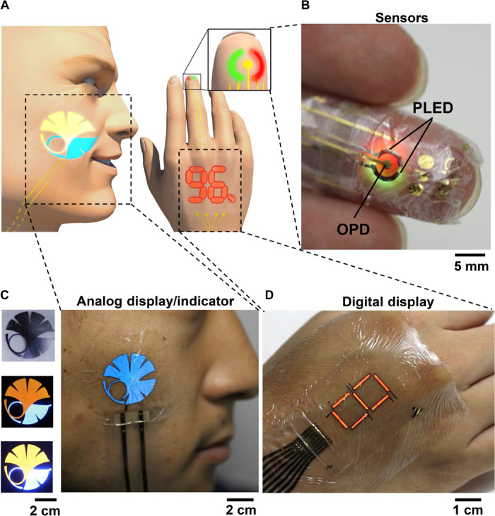
(A) Schematic illustration of the optoelectronic skins (oe-skins) system. (B) Photograph of a finger with the ultraflexible organic optical sensor attached. (C) Photographs of a human face with a blue logo of the University of Tokyo and a two-color logo. The brightness can be changed by the operation voltage. (D) Photograph of a red seven-segment PLEDs displayed on a hand.
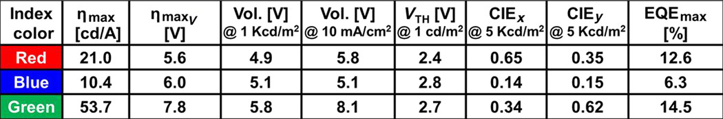
Figure 2 shows the characteristics of ultraflexible optical devices. Three-color PLEDs were manufactured on 1-μm-thick Parylene films. To realize these optical devices, transparent electrodes made from sputtered indium tin oxide (ITO) were used. To reduce heat damage to the ultraflexible substrate, we formed the ITO without substrate heating. More details of the device structure and the fabrication process are described in Materials and Methods, Fig. 2A, and fig. S3. Thanks to a reduction of the device thickness (3 μm) and placement of the active layer in the neutral strain position (39), the ultrathin PLEDs were mechanically flexible and exhibited bright electroluminescence, even when bent with a bending radius of 100 μm on the tip of a razor or crumpled (fig. S4A, Fig. 2B, and movie S2) despite using transparent conducting oxides as electrodes. These PLEDs also exhibit remarkable performance; the external quantum efficiency (EQE) and luminance of the PLEDs were, respectively, 6.2% and 1000 cd/m2 (blue, λpeak = 460 nm); 13.9% and 4900 cd/m2 (green, λpeak = 517 nm); and 12.4% and 2100 cd/m2 (red, λpeak = 609 nm) at a current density of 10 mA/cm2 (Fig. 2, C and D, figs. S4 and S5, and Table 1). These EQEs are relatively high when compared with previously reported ultraflexible PLEDs (less than 1%) and QLEDs (less than 3%) (17, 20). These exceptional electrical characteristics are especially desirable for biomedical applications because they reduce heat generation and power consumption. Our passivation layer consists of five alternating inorganic (SiON) and organic (Parylene) layers. Thanks to this flexible and thin passivation layer, our device could be operated under ambient conditions. Figure S6 shows the operational lifetime of the ultraflexible PLEDs subjected to continuous current stressing. Our passivation layer extended the operational half-life (with regard to luminance) from 2 to 29 hours. More detailed characteristics of the PLEDs are presented in figs. S4 and S5, respectively.
Fig. 2. Characteristics of ultraflexible PLEDs and OPDs.
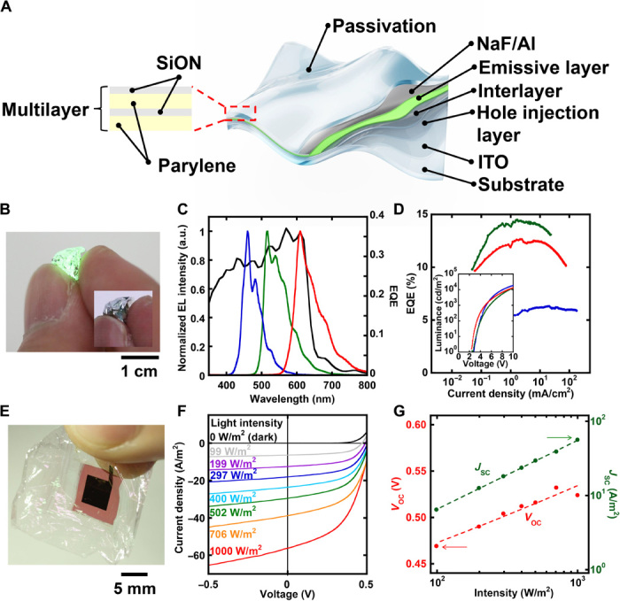
Note that all the measurements were performed in air. (A) Structure of the ultraflexible PLED. The passivation layer was composed of alternating organic (500-nm-thick Parylene) and inorganic (200-nm-thick SiON) layers. (B) Picture of the ultraflexible green PLED that was crumpled. (C) The EQE of the OPD (black line) with the normalized electroluminescence (EL) spectra of blue (blue line), green (green line), and red (red line) PLEDs. a.u., arbitrary unit. (D) Current density–dependent EQE characteristics of the ultraflexible PLEDs. The inset figure shows L-V curves of ultraflexible PLEDs. (E) Picture of the freestanding ultraflexible OPD. (F) Light intensity–dependent J-V characteristics of the OPD under simulated solar illumination. Red, orange, green, light blue, blue, purple, gray, and black represent the light intensity of 1000, 706, 502, 400, 297, 199, and 99 W/m2 and the dark condition, respectively. (G) Characteristics of the ultraflexible OPD, measured using a solar simulator. Light intensity–dependent Voc of the OPD (red) and light intensity–dependent Jsc of the OPD (green).
Table 1. Current efficiency, operation voltages, chromaticity coordinates, and the maximum EQE of three-color PLEDs.
The PLEDs exhibit almost the same current density–voltage (J-V) and luminance-voltage (L-V) characteristics as those on glass substrates, as exemplified for the green PLED (fig. S7). This was achieved by forming a polyimide planarization layer on the Parylene substrate. As a result, the surface roughness of the Parylene substrate was reduced from 3.0 to 0.48 nm (fig. S8). Subsequently, the surface roughness of the optically transparent ITO electrodes was reduced from 3.6 to 0.31 nm (fig. S9). This technique is not limited to Parylene; we observed that these processes are compatible with other ultraflexible plastic substrates (fig. S10).
In a similar fashion, OPDs comprising a poly(3-hexylthiophene) (P3HT):(6,6)-phenyl-C61-butyric acid methyl ester (PCBM) active layer were manufactured on 1-μm-thick Parylene substrates (Fig. 2E). The device structure and fabrication process are shown in fig. S11. As a benchmark, the OPDs were initially characterized using a solar simulator with an Air Mass 1.5 Global filter based on a 150-W Xe lamp (PEC-L11, Peccell Technologies) (Fig. 2, F and G). At 1 sun, we obtained a short-circuit current (Jsc) of −56.2 A/m2, an open-circuit voltage (Voc) of 0.52 V, and a fill factor of 0.50, giving a power conversion efficiency of 1.46%. For OPDs, characterizing the light intensity dependence of the Jsc and Voc is crucial for sensing applications and also for establishing the quality of the device. In bulk heterojunction–based devices, in the absence of traps and with satisfactorily low leakage currents, the Jsc should scale with a power law (40), whereas the Voc should scale logarithmically (41) with a slope equal to kT/q. In our case, remarkably low leakage currents were observed (−0.09 A/m2 at −1 V) and the scalings of the Jsc and Voc were as expected for bulk heterojunction devices. In addition, the EQE spectrum is an important factor for OPDs, defining the spectral responsivity of the photodetector. This is plotted along with the normalized electroluminescence spectra of the PLEDs in Fig. 2C.
Our organic optical devices are remarkably flexible owing to their thin form factor and low flexural rigidity. In combination with rubber substrates, these ultraflexible devices become highly stretchable (42, 43). This is achieved by laminating the device on prestretched acrylic tape–silicone rubber sheets (movie S3). Releasing the prestretch of the rubber forms an out-of-plane wrinkled structure in the optoelectronic foil. The prerequisite for freestanding or transfer-printed ultrathin electronics is a damage-free delamination process from the supporting substrate. We find that peeling off the PLEDs from the supporting substrate has negligible effects on their performance (fig. S12), with only a minor increase in the leakage current. Figure 3A shows pictures of a green stretchable PLED under compression from 0 to 67%. Even in their most compressed state, the PLEDs remain fully functional. The surface of a stretchable PLED under compression from 37% shows a wrinkled structure with a height of several hundred micrometers (Fig. 3B). These data suggested that the minimum bending radius is less than 100 μm. We also checked the cyclicability of stretching to check the flexibility of our device. The device did not degrade after 1000 cycles with 60% stretching (Fig. 3C). The measurement system and method are described in the Materials and Methods and fig. S13. We also checked the flexibility of our OPDs. Our OPD shows the almost same Voc and Jsc after 40% compression, with the dark current also remaining unchanged (Fig. 3D and fig. S14). These qualities are very important to realize a combined device that comprises both ultraflexible OPDs and PLEDs. Additionally, the OPDs did not degrade after 300 stretching cycles (Fig. 3E).
Fig. 3. Demonstrations of extreme flexibility of ultrathin optical devices.
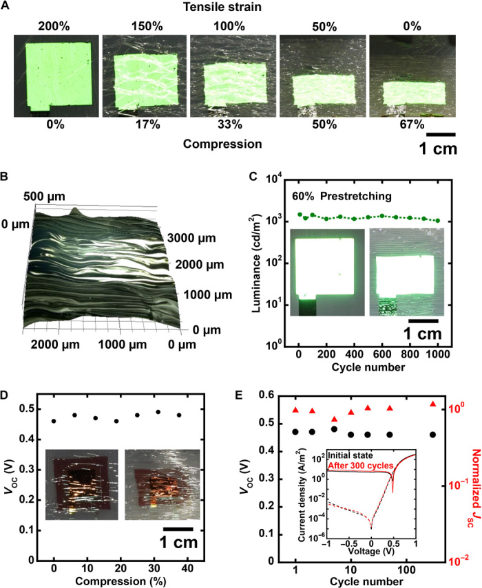
(A) Images of an ultrathin red PLED adhered to a prestretched elastomer. The images from right to left represent the transition from the wrinkled state to the flat state. (B) Three-dimensional image of the wrinkled PLED state. The prestretch value was 60%. (C) Cyclic stretching test of the green PLED. After 1000 stretching cycle tests, the light intensity was decreased by only 10%. (D) Voc of the wrinkled OPD. The inset figure shows the flat and compressed OPD. (E) Cyclic stretching test of the OPD. After 300 stretching cycle tests, the characteristics did not show any degradation. The black circles and red triangles represent the Voc and normalized Jsc, respectively. The inset figure shows the J-V characteristics of the OPD (dot line, dark state; solid line, irradiated by green light). Black and red lines represent the initial state and the state after 300 stretching cycles, respectively.
By combining ultraflexible green and red PLEDs with an OPD, we have demonstrated a flexible and conformable reflective pulse oximeter (Fig. 4, A and B). The sensitivity of the OPD under excitation by green and red PLEDs is shown in Fig. 4 (C and D) and fig. S15. The Voc of the OPDs as a function of light intensity is fitted to a logarithmic relationship (fig. S15A). The double logarithmic plot of the Jsc of the OPDs as a function of the light intensity is fitted according to power law (fig. S15B). This good logarithmic relationship between light intensity and Voc is very important in facilitating calculation of the blood/oxygen ratio (36). The pulse oximeter was laminated to the skin using adhesive tape with a thickness of 6 μm. The total thickness was approximately 30 μm, but the structure includes very soft elastomeric adhesive tapes, which do not affect the conformability. To detect pulse waves and blood oxygen levels, we turned the device over and wrapped it around a finger (Fig. 1B), so that light was emitted from the PLEDs to the body, and the reflected light was detected by the OPD (Fig. 4B). With the driving voltage of the PLEDs set at 5 V, the Voc of the OPD was monitored to measure the absorption of green and red light by the blood. Figure 4E and fig. S16 show the long-term OPDs Voc. The pulsating photoplethysmogram (PPG) signal generates little noise and good repeatability, which is enabled by the good adhesion. The baseline of the Voc is from 200 to 300 mV, from which the incident light intensity can be directly measured (fig. S15A). Our device shows good stability in air, with the PPG signal remaining constant after four days (Fig. 4F and fig. S17). We succeeded in measuring periodic cycles with amplitudes of approximately 100 to 200 μV, from which the pulse rate was measured to be 60 beats/min. When we reduced the peripheral capillary oxygen saturation (SpO2) from 99 to 90%, the amplitude of the signal also changed (Fig. 4, G and H). These results agree with previous results for an organic pulse oximeter using glass and thick plastic substrate (36).
Fig. 4. Ultraflexible organic pulse oximeter.
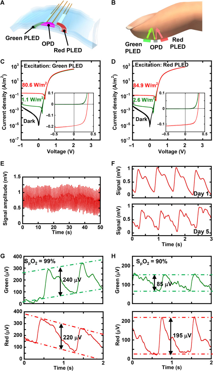
(A) Device structure of the pulse oximeter. (B) Operation principle of the reflective pulse oximeter. (C) Light intensity–dependent J-V characteristics of the OPD when irradiated by a green PLED. (D) Light intensity–dependent J-V characteristics of the OPD when irradiated by a red PLED. (E) Long-term measurement of the pulse wave. The pulse wave was measured using a red PLED and OPD. (F) Air stability of the PPG signal. The PPG signal was measured using a red PLED and OPD. (G) Output signal from OPD with 99% oxygenation of blood. The green and red lines represent the signals when the green and red PLEDs, respectively, were operated. (H) Output signal from OPD with 90% of oxygenation of blood. The green and red lines represent the signals when the green and red PLEDs, respectively, were operated.
DISCUSSION
The ultrathin organic optical systems shown in this work represent ultraflexible organic optical devices that are operated in ambient atmosphere. With a total thickness of just 3 μm, they are extremely lightweight and can endure bending radii of 100 μm or less. In combination with an engineered elastomeric substrate, such devices become highly stretchable and repeatedly sustain up to 60% compression. Such extremes in flexibility, weight, and stretchability allowed the realization of e-skins with multiple electronic functionalities, such as sensors and displays, which can be worn on the surface of human skin. A passivation layer consisting of five alternating inorganic (SiON) and organic (Parylene) layers show 5.0 × 10⁻⁴ g/m2 per day or less WVTRs and 0.1 cc/m2 per day or less oxygen transfer rates (fig. S18), values sufficient to operate the optoelectronic foils in air for several days, despite their thin form factor. When multilayers consisting of SiON and organic layers are manufactured with high-power processes on thick (125-μm) plastic and/or glass substrates, the WVTR is 10−5 g/m2 per day or less (44). Improvements of the ultrathin passivation system, and hence device lifetime, seem feasible by further optimization of the deposition conditions. Ultimately, flexible organic optical sensors may be directly laminated on organs to monitor the blood oxygen level during and after surgery.
MATERIALS AND METHODS
Polymer light-emitting diodes
The three-color LEDs were manufactured with polymeric light-emitting materials (Sumitomo Chemical Co. Ltd.). First, a 1-μm-thick Parylene layer (diX-SR, Daisan Kasei Co. Ltd.), which was to be used as a substrate after delamination, was deposited by chemical vapor deposition (CVD) on a glass plate whose surface was coated with a fluorinated polymer layer (Novec 1700, 3M Company). Then, a 500-nm-thick polyimide layer (CT4112, Kyocera Chemical Corporation) was spin-coated (4000 rpm, 60 s) as a planarization layer. A 70-nm-thick ITO layer was formed by sputtering, as a transparent electrode. After using spin coating to form a hole injection layer and an interlayer, the device was annealed in the atmosphere and nitrogen, respectively. The maximum process temperature is 180°C. Next, an active layer (blue, green, or red) was spin-coated, and the device was annealed at 150°C in nitrogen. The organic light-emitting materials consisted of a conjugated polymer system with fluorenes, phenylenes, and other polycondensed aromatic compounds as basic units and have emitting moieties in the polymers. Blue PLEDs used fluorescent emitters, whereas green and red PLEDs used phosphorescent emitters. Finally, NaF/Al was deposited as a cathode (fig. S3). After fabricating PLEDs, we formed the passivation layer, which consisted of inorganic (SiON) and organic (Parylene) layers formed by plasma-enhanced CVD and CVD, respectively. The thicknesses of the inorganic and organic layers were 200 and 500 nm, respectively (Fig. 2A). The operational lifetime was measured at 20°C and 60% relative humidity. For lifetime measurements, the PLEDs were operated at a constant current of 12.5 mA/cm2.
Organic photodetectors
The preparation of the Parylene substrate is exactly the same as for the LED fabrication process. We deposited a 70-nm-thick ITO layer and formed a very thin polyethylenimine, ethoxylated layer by means of spin coating on the Parylene substrate. Then, a P3HT:PCBM layer was formed by spin coating. Next, MoOX (14 nm) and Au (70 nm) were formed by thermal evaporation as an anode. Finally, we formed a 1-μm-thick Parylene as a passivation layer. The WVTR of 1-μm-thick Parylene was approximately 90 g/m2 per day. The details of the fabrication process are shown in fig. S11.
Stretchable experiments
In the experiment, we prepared the stretchable substrate by using acrylic tape and a silicone rubber sheet (Ecoflex 00-30, Smooth-On Inc.). Then, we laminated the ultraflexible green PLED or OPD on the prestretched substrate. In OPD experiments, we irradiated the device using a green laser (532 nm).
Pulse oximeter
The three layers (green and red PLEDs and OPD) were laminated using 6-μm adhesive tape (MK6G, Iwatani Corp.). The device was laminated on the left middle finger. In the experiment, the Voc of OPD was monitored by an oscilloscope (InfiniiVision 6000, Keysight Technologies) or an evoked potential/electromyography measurement system (MEB-9102, Nihon Kohden Corporation). The driving voltage of the PLEDs was set at 6 V, and green and red PLEDs were alternately turned on and off per every 5 s. At the same time, the oxygen saturation was measured by a commercial pulse oximeter (H100B, Edan Instruments Inc.). The peripheral capillary oxygen saturation (SpO2) can be expressed as a function of transmitted light ratio (ROS) of green and red PLEDs. We calculated the green and red PPG signal amplitudes and then calculated the ROS. ROS values were measured for various SpO2 values. The irradiance of the PLED was calibrated using an inorganic PD by changing the operation voltage. All experiments were approved by the Ethics Committee of the University of Tokyo (approval no. KE14-37).
Supplementary Material
Acknowledgments
We express our sincere gratitude to Sumitomo Chemical Co. Ltd. for supplying polymer materials for PLEDs. We also thank Mitsui Chemicals Inc. for transparent polyimide and Daisan Kasei Co. Ltd. for high-purity Parylene (diX-SR). We thank K. Tajima (RIKEN) and his research group for assistance in measurement of the OPD characteristics. We thank T. Sekitani (Osaka University) for assistance in experiments of the PLED and discussion. We are indebted to S. Lee, R. Shidachi, and T. Nakamura for their fruitful discussions on this topic. N.M. thanks the support provided by the research fellowships for the Advanced Leading Graduate Course for Photon Science. Funding: This work was financially supported by the JST ERATO Someya Bio-Harmonized Electronics Project. Author contributions: T.Y., P.Z., H.J., W.Y., M. Koizumi, and T.S. designed and fabricated the PLED devices. T.Y., P.Z., M. Kaltenbrunner, N.M., H.K., M. Koizumi, and T.S. designed and fabricated the OPD devices. T.Y., H.J., H.K., and Y.T. fabricated and characterized the passivation layer. T.Y., P.Z., M. Kaltenbrunner, and T.S. prepared the manuscript. T.S. supervised this project. Competing interests: The authors declare that they have no competing interests. Data and materials availability: All data needed to evaluate the conclusions in the paper are present in the paper and/or the Supplementary Materials. Additional data related to this paper may be requested from the authors.
SUPPLEMENTARY MATERIALS
Supplementary material for this article is available at http://advances.sciencemag.org/cgi/content/full/2/4/e1501856/DC1
fig. S1. Ultraflexible seven-segment display on hands (showing numbers from 0 to 9).
fig. S2. Ultraflexible seven-segment display on hands (showing letters from A to Z).
fig. S3. The fabrication process of ultraflexible PLEDs.
fig. S4. Picture and characteristics of ultraflexible PLEDs.
fig. S5. CIE 1931 chromaticity coordinates (x, y) of PLEDs on ultraflexible substrates.
fig. S6. Lifetime test of the ultraflexible green PLEDs.
fig. S7. Characteristics of green PLEDs on a glass substrate (red) and an ultraflexible substrate (blue).
fig. S8. Surface roughness of the ultraflexible substrate.
fig. S9. Surface roughness of ITO electrodes on an ultraflexible substrate.
fig. S10. Characteristics of green PLEDs on 2-μm-thick transparent polyimide substrate (red) and 1.4-μm-thick polyethylene terephthalate substrates (blue).
fig. S11. Fabrication process of ultraflexible OPDs.
fig. S12. Green PLED characteristics before and after peeling from a supporting substrate.
fig. S13. Measurement setup for the cyclic stretching test.
fig. S14. J-V characteristics of the OPD (dot line, dark state; solid line, irradiated by a green laser (532 nm).
fig. S15. Characteristics of the OPD with green and red PLED irradiation.
fig. S16. Output signals from OPDs irradiated with PLEDs.
fig. S17. Air stability of the PPG signal.
fig. S18. Characteristics of the passivation layer.
Supplementary Materials and Methods
movie S1. Operation of seven-segment display on hands.
movie S2. Operation of crumpled green PLED.
movie S3. Demonstrations of extreme flexibility of ultraflexible PLEDs.
REFERENCES AND NOTES
- 1.Schwartz G., Tee B. C.-K., Mei J., Appleton A. L., Kim D. H., Wang H., Bao Z., Flexible polymer transistors with high pressure sensitivity for application in electronic skin and health monitoring. Nat. Commun. 4, 1859 (2013). [DOI] [PubMed] [Google Scholar]
- 2.Gao L., Zhang Y., Malyarchuk V., Jia L., Jang K.-I., Webb R. C., Fu H., Shi Y., Zhou G., Shi L., Shah D., Huang X., Xu B., Yu C., Huang Y., Rogers J. A., Epidermal photonic devices for quantitative imaging of temperature and thermal transport characteristics of the skin. Nat. Commun. 5, 4938 (2014). [DOI] [PubMed] [Google Scholar]
- 3.Wang X., Gu Y., Xiong Z., Cui Z., Zhang T., Silk-molded flexible, ultrasensitive, and highly stable electronic skin for monitoring human physiological signals. Adv. Mater. 26, 1336–1342 (2014). [DOI] [PubMed] [Google Scholar]
- 4.Nirenberg S., Pandarinath C., Retinal prosthetic strategy with the capacity to restore normal vision. Proc. Natl. Acad. Sci. U.S.A. 109, 15012–15017 (2012). [DOI] [PMC free article] [PubMed] [Google Scholar]
- 5.Hochberg L. R., Bacher D., Jarosiewicz B., Masse N. Y., Simeral J. D., Vogel J., Haddadin S., Liu J., Cash S. S., van der Smagt P., Donoghue J. P., Reach and grasp by people with tetraplegia using a neurally controlled robotic arm. Nature 485, 372–375 (2012). [DOI] [PMC free article] [PubMed] [Google Scholar]
- 6.Muensterer O. J., Lacher M., Zoeller C., Bronstein M., Kübler J., Google Glass in pediatric surgery: An exploratory study. Int. J. Surg., 12, 281–289 (2014). [DOI] [PubMed] [Google Scholar]
- 7.Liao Y. T., Yao H., Lingley A., Parviz B., Otis B. P., A 3-μW CMOS glucose sensor for wireless contact-lens tear glucose monitoring. IEEE J. Solid-St. Circ. 47, 335–344 (2012). [Google Scholar]
- 8.Lenzi T., De Rossi S. M. M., Vitiello N., Carrozza M. C., Intention-based EMG control for powered exoskeletons. IEEE Trans. Biomed. Eng. 59, 2180–2190 (2012). [DOI] [PubMed] [Google Scholar]
- 9.Someya T., Sekitani T., Iba S., Kato Y., Kawaguchi H., Sakurai T., A large-area, flexible pressure sensor matrix with organic field-effect transistors for artificial skin applications. Proc. Natl. Acad. Sci. U.S.A. 101, 9966–9970 (2004). [DOI] [PMC free article] [PubMed] [Google Scholar]
- 10.Someya T., Kato Y., Sekitani T., Iba S., Noguchi Y., Murase Y., Kawaguchi H., Sakurai T., Conformable, flexible, large-area networks of pressure and thermal sensors with organic transistor active matrixes. Proc. Natl. Acad. Sci. U.S.A. 102, 12321–12325 (2005). [DOI] [PMC free article] [PubMed] [Google Scholar]
- 11.Takei K., Takahashi T., Ho J. C., Ko H., Gillies A. G., Leu P. W., Fearing R. S., Javey A., Nanowire active-matrix circuitry for low-voltage macroscale artificial skin. Nat. Mater. 9, 821–826 (2010). [DOI] [PubMed] [Google Scholar]
- 12.Ramuz M., Tee B. C.-K., Tok J. B.-H., Bao Z., Transparent, optical, pressure-sensitive artificial skin for large-area stretchable electronics. Adv. Mater. 24, 3223–3227 (2012). [DOI] [PubMed] [Google Scholar]
- 13.Kim D.-H., Lu N., Ma R., Kim Y.-S., Kim R.-H., Wang S., Wu J., Won S. M., Tao H., Islam A., Yu K. J., Kim T.-., Chowdhury R., Ying M., Xu L., Li M., Chung H.-J., Keum H., McCormick M., Liu P., Zhang Y.-W., Omenetto F. G., Huang Y., Coleman T., Rogers J. A., Epidermal electronics. Science 333, 838–843 (2011). [DOI] [PubMed] [Google Scholar]
- 14.Huang X., Liu Y., Cheng H., Shin W.-J., Fan J. A., Liu Z., Lu C.-J., Kong G.-W., Chen K., Patnaik D., Lee S.-H., Hage-Ali S., Huang Y., Rogers J. A., Materials and designs for wireless epidermal sensors of hydration and strain. Adv. Funct. Mater. 24, 3846–3854 (2014). [Google Scholar]
- 15.Fukuda K., Takeda Y., Yoshimura Y., Shiwaku R., Tran L. T., Sekine T., Mizukami M., Kumaki D., Tokito S., Fully-printed high-performance organic thin-film transistors and circuitry on one-micron-thick polymer films. Nat. Commun. 5, 4147 (2014). [DOI] [PubMed] [Google Scholar]
- 16.Kim R. H., Kim H. J., Bae I., Hwang S. K., Velusamy D. B., Cho S. M., Takaishi K., Muto T., Hashizume D., Uchiyama M., André P., Mathevet F., Heinrich B., Aoyama T., Kim D.-E., Lee H., Ribierre J.-C., Park C., Non-volatile organic memory with sub-millimetre bending radius. Nat. Commun. 5, 3583 (2014). [DOI] [PubMed] [Google Scholar]
- 17.White M. S., Kaltenbrunner M., Głowacki E. D., Gutnichenko K., Kettlgruber G., Graz I., Aazou S., Ulbricht C., Egbe D. A. M., Miron M. C., Major Z., Scharber M. C., Sekitani T., Someya T., Bauer S., Sariciftci N. S., Ultrathin, highly flexible and stretchable PLEDs. Nat. Photonics 7, 811–816 (2013). [Google Scholar]
- 18.Kaltenbrunner M., White M. S., Głowacki E. D., Sekitani T., Someya T., Sariciftci N. S., Bauer S., Ultrathin and lightweight organic solar cells with high flexibility. Nat. Commun. 3, 770 (2012). [DOI] [PMC free article] [PubMed] [Google Scholar]
- 19.Kaltenbrunner M., Sekitani T., Reeder J., Yokota T., Kuribara K., Tokuhara T., Drack M., Schwödiauer R., Graz I., Bauer-Gogonea S., Bauer S., Someya T., An ultra-lightweight design for imperceptible plastic electronics. Nature 499, 458–463 (2013). [DOI] [PubMed] [Google Scholar]
- 20.Choi M. K., Yang J., Kang K., Kim D. C., Choi C., Park C., Kim S. J., Chae S. I., Kim T.-H., Kim J. H., Hyeon T., Kim D.-H., Wearable red–green–blue quantum dot light-emitting diode array using high-resolution intaglio transfer printing. Nat. Commun. 6 7149 (2015). [DOI] [PMC free article] [PubMed] [Google Scholar]
- 21.Fujisaki Y., Nakajima Y., Takei T., Fukagawa H., Yamamoto T., Fujikake H., Flexible active-matrix organic light-emitting diode display using air-stable organic semiconductor of dinaphtho[2,3-b:2′,3′-f]thieno[3,2-b]-thiophene. IEEE T. Electron Dev. 59, 3442–3449 (2012). [Google Scholar]
- 22.Nakajima Y., Nakata M., Takei T., Fukagawa H., Motomura G., Tsuji H., Shimizu T., Fujisaki Y., Kurita T., Yamamoto T., Development of 8-in. oxide-TFT-driven flexible AMOLED display using high-performance red phosphorescent OLED. J. Soc. Inf. Display 22, 137–143 (2014). [Google Scholar]
- 23.Reineke S., Lindner F., Schwartz G., Seidler N., Walzer K., Lüssem B., Leo K., White organic light-emitting diodes with fluorescent tube efficiency. Nature 459 234–238 (2009). [DOI] [PubMed] [Google Scholar]
- 24.Uoyama H., Goushi K., Shizu K., Nomura H., Adachi C., Highly efficient organic light-emitting diodes from delayed fluorescence. Nature 492 234–238 (2012). [DOI] [PubMed] [Google Scholar]
- 25.Aizawa N., Pu Y.-J., Watanabe M., Chiba T., Ideta K., Toyota N., Igarashi M., Suzuri Y., Sasabe H., Kido J., Solution-processed multilayer small-molecule light-emitting devices with high-efficiency white-light emission. Nat. Commun. 5, 5756 (2014). [DOI] [PubMed] [Google Scholar]
- 26.Zhang Q., Li B., Huang S., Nomura H., Tanaka H., Adachi C., Efficient blue organic light-emitting diodes employing thermally activated delayed fluorescence. Nat. Photonics 8, 326–332 (2014). [Google Scholar]
- 27.Udagawa K., Sasabe H., Cai C., Kido J., Low-driving-voltage blue phosphorescent organic light-emitting devices with external quantum efficiency of 30%. Adv. Mater. 26, 5062–5066 (2014). [DOI] [PubMed] [Google Scholar]
- 28.Burroughes J. H., Bradley D. D. C., Brown A. R., Marks R. N., Mackay K., Friend R. H., Burns P. L., Holmes A. B., Light-emitting diodes based on conjugated polymers. Nature 347, 539–541 (1990). [Google Scholar]
- 29.Gustafsson G., Cao Y., Treacy G. M., Klavetter F., Colaneri N., Heeger A. J., Flexible light-emitting diodes made from soluble conducting polymers. Nature 357, 477–479 (1992). [Google Scholar]
- 30.Png R.-Q., Chia P.-J., Tang J.-C., Liu B., Sivaramakrishnan S., Zhou M., Khong S.-H., Chan H. S. O., Burroughes J. H., Chua L.-L., Friend R. H., Ho P. K. H., High-performance polymer semiconducting heterostructure devices by nitrene-mediated photocrosslinking of alkyl side chains. Nat. Mater. 9, 152–158 (2010). [DOI] [PubMed] [Google Scholar]
- 31.Liang J., Li L., Niu X., Yu Z., Pei Q., Elastomeric polymer light-emitting devices and displays. Nat. Photonics 7, 817–824 (2013). [Google Scholar]
- 32.Rauch T., Böberl M., Tedde S. F., Fürst J., Kovalenko M. V., Hesser G., Lemmer U., Heiss W., Hayden O., Near-infrared imaging with quantum-dot-sensitized organic photodiodes. Nat. Photonics 3, 332–336 (2009). [Google Scholar]
- 33.Gong X., Tong M., Xia Y., Cai W., Moon J. S., Cao Y., Yu G., Shieh C.-L., Nilsson B., Heeger A. J., High-detectivity polymer photodetectors with spectral response from 300 nm to 1450 nm. Science 325, 1665–1667 (2009). [DOI] [PubMed] [Google Scholar]
- 34.Baeg K.-J., Binda M., Natali D., Caironi M., Noh Y.-Y., Organic light detectors: Photodiodes and phototransistors. Adv. Mater. 25, 4267–4295 (2013). [DOI] [PubMed] [Google Scholar]
- 35.Park S., Kim S. J., Nam J. H., Pitner G., Lee T. H., Ayzner A. L., Wang H., Fong S. W., Vosgueritchian M., Park Y. J., Brongersma M. L., Bao Z., Significant enhancement of infrared photodetector sensitivity using a semiconducting single-walled carbon nanotube/C60 phototransistor. Adv. Mater. 27, 759–765 (2015). [DOI] [PubMed] [Google Scholar]
- 36.Lochner C. M., Khan Y., Pierre A., Arias A. C., All-organic optoelectronic sensor for pulse oximetry. Nat. Commun. 5, 5745 (2014). [DOI] [PubMed] [Google Scholar]
- 37.Bansal A. K., Hou S., Kulyk O., Bowman E. M., Samuel I. D. W., Wearable organic optoelectronic sensors for medicine. Adv. Mater. 27, 7638–7644 (2015). [DOI] [PubMed] [Google Scholar]
- 38.Dennler G., Lungenschmied C., Neugebauer H., Sariciftci N. S., Labouret A., Flexible, conjugated polymer-fullerene-based bulk-heterojunction solar cells: Basics, encapsulation, and integration. J. Mater. Res. 20, 3224–3233 (2005). [Google Scholar]
- 39.Sekitani T., Someya T., Air-stable operation of organic field-effect transistors on plastic films using organic/metallic hybrid passivation layers. Jpn. J. Appl. Phys. 46, 4300–4306 (2007). [Google Scholar]
- 40.Koster L. J. A., Mihailetchi V. D., Ramaker R., Blom P. W. M., Light intensity dependence of open-circuit voltage of polymer:fullerene solar cells. Appl. Phys. Lett. 86, 123509 (2005). [Google Scholar]
- 41.Koster L. J. A., Mihailetchi V. D., Xie H., Blom P. W. M., Origin of the light intensity dependence of the short-circuit current of polymer/fullerene solar cells. Appl. Phys. Lett. 87, 203502 (2005). [Google Scholar]
- 42.Biot M. A., Folding instability of a layered viscoelastic medium under compression. P. Roy. Soc. A-Math. Phy. 242, 444–454 (1957). [Google Scholar]
- 43.Wang Q., Zhao X., A three-dimensional phase diagram of growth-induced surface instabilities. Sci. Rep. 5, 8887 (2015). [DOI] [PMC free article] [PubMed] [Google Scholar]
- 44.Kim T. W., Yan M., Erlat A. G., McConnelee P. A., Pellow M., Deluca J., Feist T. P., Duggal A. R., Schaepkens M., Transparent hybrid inorganic/organic barrier coatings for plastic organic light-emitting diode substrates. J. Vac. Sci. Technol. A 23, 971–977 (2005). [Google Scholar]
Associated Data
This section collects any data citations, data availability statements, or supplementary materials included in this article.
Supplementary Materials
Supplementary material for this article is available at http://advances.sciencemag.org/cgi/content/full/2/4/e1501856/DC1
fig. S1. Ultraflexible seven-segment display on hands (showing numbers from 0 to 9).
fig. S2. Ultraflexible seven-segment display on hands (showing letters from A to Z).
fig. S3. The fabrication process of ultraflexible PLEDs.
fig. S4. Picture and characteristics of ultraflexible PLEDs.
fig. S5. CIE 1931 chromaticity coordinates (x, y) of PLEDs on ultraflexible substrates.
fig. S6. Lifetime test of the ultraflexible green PLEDs.
fig. S7. Characteristics of green PLEDs on a glass substrate (red) and an ultraflexible substrate (blue).
fig. S8. Surface roughness of the ultraflexible substrate.
fig. S9. Surface roughness of ITO electrodes on an ultraflexible substrate.
fig. S10. Characteristics of green PLEDs on 2-μm-thick transparent polyimide substrate (red) and 1.4-μm-thick polyethylene terephthalate substrates (blue).
fig. S11. Fabrication process of ultraflexible OPDs.
fig. S12. Green PLED characteristics before and after peeling from a supporting substrate.
fig. S13. Measurement setup for the cyclic stretching test.
fig. S14. J-V characteristics of the OPD (dot line, dark state; solid line, irradiated by a green laser (532 nm).
fig. S15. Characteristics of the OPD with green and red PLED irradiation.
fig. S16. Output signals from OPDs irradiated with PLEDs.
fig. S17. Air stability of the PPG signal.
fig. S18. Characteristics of the passivation layer.
Supplementary Materials and Methods
movie S1. Operation of seven-segment display on hands.
movie S2. Operation of crumpled green PLED.
movie S3. Demonstrations of extreme flexibility of ultraflexible PLEDs.