Abstract
A PET detector with good timing resolution and two-level depth-of-interaction (DOI) discrimination can be constructed using a single-ended readout of scintillator stacks of Lanthanum Bromide (LaBr3), with various Cerium dopant concentrations, including pure Cerium Bromide (CeBr3). The stacked crystal geometry creates a unique signal shape for interactions occurring in each layer, which can be used to identify the DOI, while retaining the inherently good timing properties of LaBr3 and CeBr3. In this work, single pixel elements are used to optimize the choice of scintillator, coupling of layers, and type of photodetector, evaluating the performance using a fast, single-channel photomultiplier tube (PMT) and a single 4×4 mm2 silicon photomultiplier (SiPM). We also introduce a method to quantify and evaluate the DOI discrimination accuracy. From signal shape measurements using fast waveform sampling, we found that in addition to differences in signal rise times, between crystal layers, there were also differences in the signal fall times. A DOI accuracy of 98% was achieved using our classification method for a stacked crystal pair, consisting of a 15-mm long LaBr3(Ce:20%) crystal on top of a 15-mm long CeBr3 crystal, readout using a PMT. A DOI accuracy of 95% was measured with a stack of two, identical, 12-mm long, CeBr3 crystals. The DOI accuracy of this crystal pair was reduced to 91% when using a SiPM for readout. For the stack of two, 12-mm long, CeBr3 crystals, a coincidence timing resolution (average of timing results from the top and bottom layer) of 199 ps was measured using a PMT, and this was improved to 153 ps when using a SiPM. These results show that with stacked LaBr3/CeBr3 scintillators and fast waveform sampling nearly perfect DOI accuracy can be achieved with excellent timing resolution—timing resolution that is only minimally degraded compared to results from a single CeBr3 crystal of comparable length to the stacked crystals. The interface in the stacked crystal geometry itself plays a major role in creating the differences in signal shape and this can be used to construct stacked DOI detectors using the same scintillator type, thereby simplifying and broadening the application of this technique.
1. Introduction
It has been shown that improved PET image quality can be achieved with a detector design capable of measuring both time-of-flight (TOF) and depth-of-interaction (DOI) information (Surti et al 2013, Thoen et al 2013). However the challenge of combining both features, without significant degradations and trade-offs, has yet to be realized. Many DOI detector concepts are now being reevaluated, to characterize and improve their timing performance, so that both TOF and DOI can be measured (Schaart et al 2009, Liu et al 2012, Wiener et al 2013, Cosentino et al 2012, Schmall et al 2014, Yeom et al 2014). Our approach is to use very fast scintillators in a stacked geometry, creating a depth-dependent change in signal shape, between layers, to encode the DOI. In this work we will focus on Lanthanum Bromide (LaBr3) (van Loef et al 2001) and Cerium Bromide (CeBr3) (Shah et al 2004) scintillators. Advantages of these scintillators include their very high light output and short decay time—creating a scintillation pulse with very good timing properties.
Compared to LSO and LYSO scintillators, PET detector designs incorporating LaBr3 (or CeBr3) require longer crystal lengths, to compensate for the lower stopping power at 511 keV and increase the detector sensitivity (Kuhn et al 2004). A LaBr3(Ce:5%) based scanner (La-PET), developed at the University of Pennsylvania, uses a crystal array with individual pixel dimensions of 4×4×30 mm3 (Kyba et al 2007, Daube-Witherspoon et al 2010). In comparison with commercial TOF-PET scanners, using light sharing detector designs but based on LSO or LYSO, crystal arrays are 20–22 mm in length (Surti et al 2007, Jakoby et al 2011, Bettinardi et al 2011). A detector with 30-mm long crystals will have increased scintillation photon dispersion within the scintillator volume and a more pronounced depth-dependent variation in time pick-off (Moses and Derenzo 1999, Gundacker et al 2014)—both effects contributing to a deterioration in timing resolution. A PET system using long crystals will also have an increased parallax error, leading to a radial degradation in image spatial resolution. Therefore, detector designs based on LaBr3/CeBr3 can potentially benefit more by including techniques to measure DOI, as this information can be used to correct for timing uncertainties caused by the use of longer length crystals (Shibuya et al 2008, Spanoudaki and Levin 2011), as well as reduce parallax error in the reconstructed images.
Our initial TOF-DOI detector design used rise time differences between LaBr3 scintillators having different Cerium (Ce3+) dopant concentrations, and the feasibility was demonstrated using a dual-layer pixel composed of a Ce:30% doped layer and a Ce:5% doped layer (Wiener et al 2013). Faster signal rise times are measured using higher Ce3+ concentrations and this leads to an improvement in timing resolution (Glodo et al 2005). However, it has been reported that high Ce3+ dopant concentrations in LaBr3 scintillators causes an increase in self-absorption and re-emission (van Dam et al 2012, Quarati et al 2013). This will have a minimal influence on the signal rising edge, as photons collected here are typically emitted toward the photodetector and therefore undergo fewer reflections, but it can lead to a lengthening of the signal decay time. Because of the high light output of LaBr3 and CeBr3, the pulse from the photodetector has very good signal-to-noise properties, allowing subtle, depth-dependent differences in light transport within the scintillator to be observed. For our stacked crystal design, in addition to rise time differences between layers, we can create differences in the signal fall time by using scintillators with high Ce3+ dopant concentrations in both layers.
The experiments presented in this work use single pixel elements, the results of which aim to guide the development of a pixelated whole-body PET detector using stacked crystal arrays, and also serves to feature potential applications of LaBr3/CeBr3 scintillators and fast waveform sampling electronics. By carefully studying how the scintillation pulse is changed when using individual crystals in a stacked geometry, general trends can be inferred related to the trade-off between DOI resolution and timing resolution. This can be characterized through measurement of the signal shapes at different depths; large differences in signal shape, between layers, improves DOI resolution, and having very fast signal shapes in both layers, produces betting timing resolution. In addition to layer differences in dopant concentration, the signal shape is altered due to changes in light transport caused by the increased ‘effective length’ of the crystal (when stacked, scintillation light must travel farther to reach the photodetector) and by the added crystal-to-crystal interface. Initial measurements of scintillation characteristics and light transport are performed using a photomultiplier tube (PMT)—here properties of the signal are easily interpreted because the PMT has a small influence on pulse shape. We also investigated the detector performance using a silicon photomultiplier (SiPM). Detector designs based on SiPMs are of interest because of their ability to be used in PET/MR imaging and their potential to improve timing resolution (Roncali and Cherry 2011).
This work is organized into three main sections. First, measurements with a stacked crystal pair consisting of LaBr3(Ce:20%) on CeBr3 using a PMT readout are performed, studying the impact of crystal length, with stacks of 5-mm and 15-mm long crystals, and influence of the crystal-to-crystal coupling, using materials having a different index of refraction. Based on these results, the feasibility of using the same scintillator in each layer was explored using several different scintillator materials. Lastly, measurements using a SiPM to readout the crystal stack were performed, and the benefits and drawbacks are discussed by comparison to the results obtained using a PMT.
2. Experimental setup and methods
2.1 Signal acquisition and analysis
All measurements were performed inside of a dry box so that the hygroscopic crystals could be handled without encapsulation, allowing for repeated polishing of the crystal surfaces and direct coupling of the crystal to the photodetector. The surfaces of the crystals were polished until the surface resembled an optical polish and then wrapped in Teflon tape. When stacking the crystals, several different optical coupling materials were used for the crystal-to-crystal coupling: BC-630 silicon optical grease (Saint-Gobain Crystals, Hiram, OH) n = 1.46, Meltmount (Cargille Labs, Cedar Grove, NJ) n = 1.58, and Meltmount n = 1.68; Meltmount n = 1.68 has high optical absorption from 300 nm – 450 nm. The thickness of the coupling was less than 250 μm in all measurements. For coupling between the photodetector surface and crystal surface, optical grease (BC-630) was used in all measurements and configurations. The crystals used, and their initial measured characteristics, are listed in table 1. A 925 kBq 22Na point source was used in all measurements. Two photodetectors were used for readout: a Hamamatsu R4998 PMT and a 4×4 mm2 near ultra-violet (NUV) optimized SiPM from FBK (Pro et al 2013). No shaping or amplification was used on the PMT signal. The NUV-SiPM was read out using a custom analog circuit to create a shaped timing signal (Gola et al 2013). The energy response of the PMT was calibrated, and therefore values of FWHM/511 keV photopeak position represent true energy resolution. There was no energy calibration applied to the SiPM setup.
Table 1.
Table with all crystals used in this work and their initial measured characteristics using R4998 PMT. The cross section of all crystals was 4 mm × 4 mm.
| Scintillator & pixel length (mm) | 10–50% rise time (ns) | Decay constant (ns) | Light collection (V* ns) | Energy resolution | CTR (ps) |
|---|---|---|---|---|---|
| LaBr3(Ce:5%) 15-mm* | 1.2 | 16.5 | 113 | 4.6% | 177 |
| LaBr3(Ce:20%) 15-mm | 0.84 | 20.1 | 118 | 4.4% | 158 |
| LaBr3(Ce:20%) 5-mm | 0.75 | 17.8 | 146 | 4.2% | 98 |
| CeBr3 5-mm | 0.73 | 17.3 | 116 | 5.5% | 103 |
| CeBr3 15-mm | 0.78 | 21.7 | 104 | 5.7% | 169 |
| CeBr3 30-mm | 1.12 | 23.8 | 70 | 6.1% | 232 |
| CeBr3 12-mm* | 0.74 | 19.8 | 132 | 5.1% | 138 |
| LYSO 11-mm* | 0.95 | 41.2 | 47 | 12% | 252 |
Two identical crystals were used; the data shown are from an average of their individual characteristics.
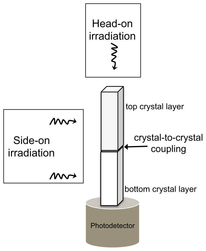
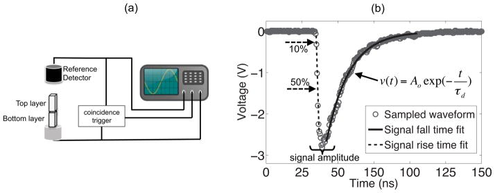
Two different reference detectors were used for coincidence measurements, corresponding to a head-on (cumulative depth irradiation) and a side-on (fixed depth irradiation) geometry (see figure 1). Measurements in a head-on irradiation geometry used a Photonis XP20D0 PMT coupled to an encapsulated LaBr3(Ce:5%) crystal (length 18mm, diameter 14mm) as the reference detector (individual detector timing 165 ps). Measurements in a side-on geometry used a 3×3×5 mm3 LYSO crystal coupled to a RGB-HD SiPM (Ferri et al 2014) as the reference detector (individual detector timing 185 ps), with the source positioned such that the beam width is estimated to be 1 mm. Waveform sampling at 2 Gs/sec (Agilent DC271) was used for all measurements, with post processing of the data performed in Matlab; coincidence events were determined using NIM-based discriminators and logic units (see figure 2a). For all results shown, photopeak event gating was applied. An optimized digital leading edge discriminator was used for time pick-off, and for timing resolution measurements with a dual-layer detector, the same threshold was used in both layers. Timing resolution, in all instances, is reported as the estimated coincidence timing resolution (CTR) with the contribution of the reference detector removed and substituted for a second detector identical to the primary detector being measured.
Figure 1.
Schematic of the stacked crystal geometry, with definitions that are used in the work.
Figure 2.
a) Electronic schematic of the detector readout. b) An example sampled waveform showing the calculated signal metrics: signal amplitude (calculated from the samples around the maximum pulse height), 10%-50% rise time and estimation of td based on the fall time fit.
Many different methods have been proposed for pulse shape modeling, typically focusing on the extraction of depth information from the signal fall time using analog electronics (Saoudi et al 1999, Schmand et al 1999). Waveform sampling using digitizing electronics enables DOI information to be extracted from the entire scintillation pulse (Du et al 2009). The sampled waveform can be thought of as a convolution of three components: the intrinsic scintillation emission process, a function describing light transport within the scintillator, and the response of the photodetector; in principle these components can be individually modeled to elucidate DOI dependent parameters. In this work, a method was developed using two independently calculated signal metrics, separately characterizing the signal rising edge and signal fall time (see figure 2b). From the sampled waveform, the signal rise time is calculated using a linear interpolation on the rising edge, and is quantified as the time it takes to go from 10% to 50% of the maximum pulse height (when using a SiPM, the rise time metric is changed to 10% to 40% for improved discrimination). The maximum pulse height is calculated as the mean of five samples surrounding the sample with the largest voltage. The signal fall time is characterized using a least square error fit to an exponential function to estimate the signal decay constant.
The computed signal metrics, of rise time and decay constant, can also be used to compute the estimated increase in timing uncertainty caused by using the crystals in a stacked geometry. Timing resolution models for fast scintillation detectors are based on a linear combination of exponential functions, describing the scintillator’s light output, intrinsic rise time, and intrinsic decay time (Shao 2007, Lecoq et al 2010). Using this formalism, the uncertainty of the first detected photon can be estimated using the equation below (Auffray et al 2011).
| [1] |
Where τd and τr refer to a rise time constant and decay time constant, and npe is the total light collected. Using this timing model, in addition to the 1/sqrt(npe) dependence, timing resolution is directly related to the square root of each scintillation time constant. Though the previously described signal metrics from the sampled waveform are not equivalent to the time constants of the model, the resulting change caused by the stacked geometry is proportional, allowing these signal metrics to be used to estimate degradations in timing performance. Equation 1 will be used to estimate the degradation in timing resolution between crystals individually coupled and crystals in a stacked geometry.
2.2 Discriminant analysis for DOI
Once the two signal metrics have been calculated from the sampled waveform, a discriminant analysis framework is used to classify events in either the top or bottom crystal layer. Based on the assumption that the measured signal metrics follow a Gaussian distribution, we compute an optimal classifier based on a set of training data (Roncali et al 2012). Because we have only two DOI bins, DOI performance is quantified using a simple error rate metric, shown in equation 2.
| [2] |
DOI accuracy is measured using a side-on irradiation geometry, to isolate events in the central depth of each stacked crystal layer, creating a ground truth data set. The two data sets are then combined and then partitioned into two independent groups. One group was used to train the classifier, and the other group was used to test the classifier’s ability to correctly predict the DOI. A quadratic discriminant function was used to separate the groups.
3. Results
3.1 Characteristics of stacked crystal pairs composed of LaBr3(Ce:20%) on CeBr3
3.1.1 Light collection
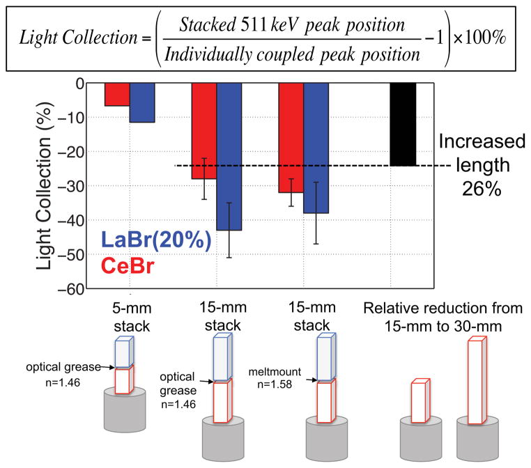
Transmission of scintillation light through the crystal-to-crystal interface was quantified from measurements with the crystals individually coupled to the PMT, followed by their use in a stacked geometry—light collection is calculated as the relative reduction in the photopeak position. Figure 3 shows light collection values, for the top and bottom crystal layers, using stacked crystal pairs of different lengths and using different coupling materials in the crystal-to-crystal interface. There is a small (~10%) reduction in light collection when stacking the two 5-mm long crystals; here the effective length was increased from 5-mm to 10-mm. With two 15-mm stacked crystals, representing an effective length increase from 15-mm to 30-mm, the reduction in light collection is much larger (~35%). Changing the crystal-to-crystal coupling from n=1.46 to n=1.58 does not significantly improve light collection, suggesting that the added interface and crystal coupling are not the dominant factor influencing light collection. Compared to light collection measurements with a 30-mm long CeBr3 crystal, we estimate that of the ~35% decrease in light collection, 26% is due to the increase in the crystals’ effective length (from 15-mm to 30-mm)—leaving the remaining ~10–15% due to the effects of the added interface. This is consistent with results from the stack of two 5-mm long crystals, where the decrease in light collection is ~10%.
Figure 3.
A summary of measurements characterizing the transmission of scintillation light through the stacked interface. Error bars represent ±σ from multiple repeat measurements where the crystal stack was taken apart and then glued together again.
3.1.2 Energy resolution and timing resolution
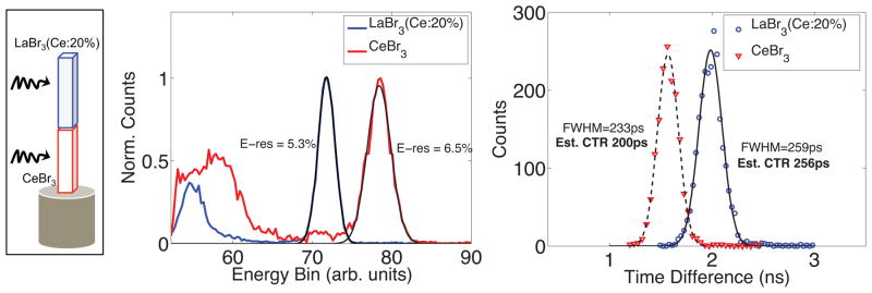
Shown in figure 4 are the timing and energy resolution results from a stacked crystal pair consisting of a 15-mm long LaBr3(Ce:20%) on a 15-mm long CeBr3 (crystal-to-crystal coupling n=1.58), using a side-on irradiation geometry read out using a PMT. The side-on irradiation geometry allows the irradiation depth to be controlled, and for these measurements it was set to the central depth in each crystal layer. An estimated CTR of 256 ps was measured for the top LaBr3(Ce:20%) layer, and 200 ps for the bottom CeBr3 layer; the result presented is calculated for two identical stacked detectors in coincidence, with interactions in each detector occurring in the same layer. Very similar CTR results were obtained using head-on irradiation. Energy resolution is also very good, below 7% in both layers, and comparable to measured energy resolutions from 30-mm long CeBr3 crystals (Wiener et al 2010).
Figure 4.
Side-on measurements of timing resolution and energy resolution with the LaBr3(Ce:20%) and CeBr3 stacked crystal pair, readout using the R4998 PMT.
Layer-dependent changes in time pick-off and photopeak position are apparent in figure 4. Though the light output of LaBr3(20%) is slightly higher compared to CeBr3, it’s photopeak position is reduced because of the added interface and longer effective length (being the top crystal). The layer differences in time pick are also of importance, and could significantly degrade timing resolution if uncorrected. The magnitude of this layer-dependent shift in time pick-off is not fully explainable due to rise time differences, implying that the interface and effective length also play a role in delaying the time pick off of the top crystal. Extracting DOI information from the signal shape will allow layer-dependent energy and timing calibrations to be applied, greatly improving the performance of the detector.
3.1.3 DOI accuracy
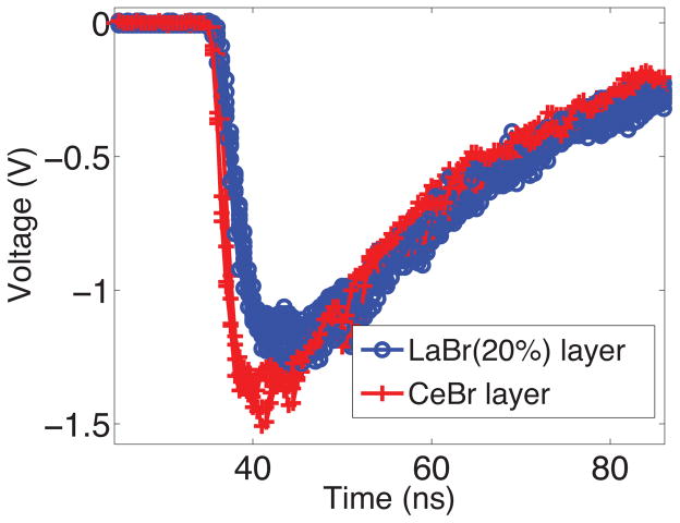
To understand how the signal shape changes because of the stacked geometry, the crystals were first characterized individually coupled to the photodetector, to measure their intrinsic signal rise time and signal decay constant properties, followed by side-on measurements with the crystals stacked. A scatter plot of the individually coupled signal rise times and signal decay constants from the 15-mm long LaBr3(Ce:20%) and CeBr3 crystals are shown figure 5a. There are minimal differences in signal properties between the two scintillators when individually coupled, with CeBr3 having a slightly faster signal rise time. When stacked (coupling n=1.58), and irradiated side-on, there are now two distinct groups, corresponding to interactions in the LaBr3(Ce:20%) and CeBr3 layers (see figure 5b); overlaid in the same plot is the calculated classifier. From these side-on measurements, where there is almost no inter-layer Compton scattering, the calculated DOI accuracy is 98.8%. Waveforms from each layer are shown in figure 6 for comparison.
Figure 5.
(a) Scatter plots showing the calculated signal rise time and signal decay constant, on an event by event basis, using a head-on irradiation. The CeBr3 and LaBr3(Ce:20%) crystals were measured separately, individually coupled to the R4998 PMT. (b) Scatter plots from side-on measurements in the stacked crystal geometry (coupling n=1.58) and overlaid is the calculated discriminant function used to classify events. The DOI classification accuracy is 98.8%.
Figure 6.
Comparison of signal shapes from the dual layer stack of 15-mm long crystals, LaBr3(Ce:20%) on CeBr3, as shown in figure 4. Events were recorded using the R4998 PMT and side-on irradiation.
3.1.4 Effect of interface coupling on signal shape
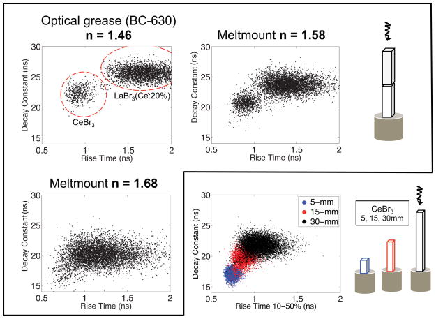
Signal properties of the LaBr3(Ce:20%) on CeBr3 crystal pair were also studied using different crystal-to-crystal couplings (n=1.46, n=1.58, n=1.68). In these experiments the stacked crystal pair was irradiated head-on, for a qualitative measurement of how layer-to-layer signal properties change when using different coupling materials. As shown in figure 7, the crystal-to-crystal coupling has a large effect on pulse shape, creating good layer separation with n=1.46 and poor separation with n=1.68. We can also see the large change in signal properties of CeBr3 crystals with varying lengths; the measured relative increase in decay time (~1.3× from 5mm to 30 mm) is very similar to other reported values for CeBr3 crystals (van Dam et al 2012 and Quarati et al 2013). When using a coupling with an index of refraction much closer matched to the scintillator’s index of refraction, which is around 1.9–2.3 (Shah et al 2003 and van damn et al 2012), the signal properties of the crystal pair are less perturbed relative to that of a 30-mm long crystal—a distribution with a single mean and an increased standard deviation for both rise time and decay constant. With a crystal-to-crystal coupling of n=1.46, scintillation light from the top layer, on average, will undergo a larger number of reflections before being detected by the PMT because of the higher reflection probability at the crystal-to-crystal interface. Longer photon path lengths cause a slowing of the signal rising edge and also increase the signal decay time. Scintillation light originating from the bottom layer, directed toward the crystal-to-crystal interface, will have a lower transmission probability, causing the average path length to be shorter. Thus the difference in signal properties between layers is much more pronounced, and DOI accuracy improved, when using lower index of refraction coupling materials for the crystal-to-crystal coupling. The opposite is observed when using a higher index of refraction coupling, however in both layers the signal rise time is faster and signal decay constant smaller, which improves timing resolution. The improvement in DOI discrimination accuracy, using n=1.46 compared with n=1.58, is shown in table 2.
Figure 7.
Signal properties of the stacked detector, irradiated head-on, using three different crystal-to-crystal coupling materials. The red circles in the n=1.46 plot qualitatively indicate the layer segmentation. To visualize how signal properties change with crystal length, measurements from CeBr3 crystals of lengths 5, 15, and 30 mm where overlaid.
Table 2.
Summary of DOI classification results. To better observe the small changes in DOI performance error rates are shown; DOI accuracy is calculated as 1 – error rate.
| Scintillator pair (top, bottom) | Interface coupling (index of ref.) | Error rate PMT | Error rate SiPM | ||
|---|---|---|---|---|---|
|
| |||||
| Both signal metrics | Decay constant only | Rise time only | Rise time only | ||
| LaBr3(5%), LaBr3(5%) | 1.46 | 7.3% | 26% | 7.3% | - |
| LaBr3(20%), CeBr3 | 1.46 | 0.7% | 2.6% | 0.9% | - |
| LaBr3(20%), CeBr3 | 1.58 | 1.2% | 4.7% | 4.4% | 4% |
| CeBr3, CeBr3 | 1.46 | 3.0% | 6.7% | 6.4% | 6.5% |
| CeBr3, CeBr3 | 1.58 | 5.1% | 9.4% | 8.8% | 8.6% |
| LYSO, LYSO | 1.46 | 45% | 46% | 44% | - |
3.2 Same scintillators in both layers
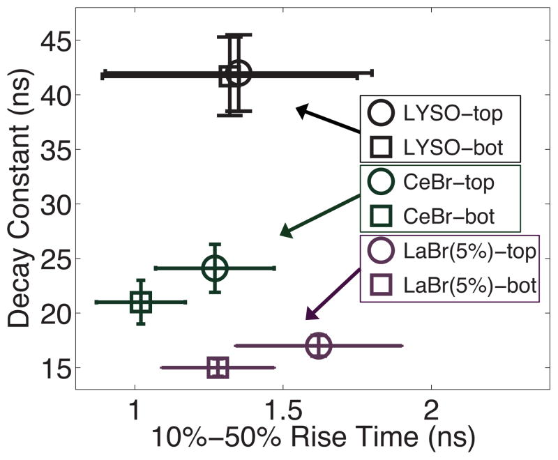
Based on the excellent DOI discrimination results with the 30-mm long crystal pair consisting of LaBr3(Ce:20%) on CeBr3 (both crystals 15-mm long), we studied crystal pairs of the same scintillation material (having the same dopant concentration), relying on the increase in effective length and added crystal-to-crystal interface to create layer-dependent differences in signal properties. The signal properties from each layer were measured with side-on irradiation and using optical grease (n=1.46) for the crystal-to-crystal coupling, for optimal layer separation. Results from scintillator pairs of 11-mm long LYSO, 15-mm long LaBr3(Ce:5%), and 12-mm long CeBr3 are shown in figure 8. For stacked crystal pairs of 11-mm long LYSO crystals, differences in signal shapes between layers were negligible. In addition, the lower light output of LYSO causes a greater variation in the measured signal shape—the calculated standard deviation of both metrics is about a factor of 2 greater compared to LaBr3(Ce:5%) or CeBr3 due to Poisson statistics and is observed in our results—therefore layer differences could not be measured using the signal metrics described in this work. With pairs of 15-mm long LaBr3(Ce:5%) crystals, rise time differences were measureable, however there were only minimal differences in the signal decay constant. From measurements with individual LaBr3(Ce:5%) crystals, we have observed smaller changes in the signal decay constant with increased crystal length, compared to LaBr3 with higher Ce3+ concentrations and also CeBr3—we believe this is due to self-absorption and re-emission in the scintillator with higher Ce3+ concentrations. Two stacked CeBr3 crystals produce measurable differences in both the signal rise time and the decay constant. For this crystal pair, measurements were also taken with a side-on irradiation setup and using a crystal-to-crystal coupling of n=1.58; the calculated error rates using both couplings are given in table 2. The DOI accuracy with two CeBr3 crystals is better when using a coupling of n=1.46, but overall, the DOI accuracy is worse for same scintillator pairs compared to the crystal pair of LaBr3(Ce:20%) on CeBr3.
Figure 8.
Signal characteristics of crystal pairs consisting of the same scintillation material; for LYSO a stack of two identical 4×4×11 mm3 crystals were used, for CeBr3 two 4×4×12 mm3, and LaBr3(Ce:5%) two 4×4×15 mm3. Optical grease was used for the crystal-to-crystal coupling (n=1.46). Using a large set of acquired waveforms the mean signal rise time and signal decay constant is plotted, from two side-on acquisitions in the center of each crystal layer; error bars represent two standard deviations in both signal rise time and signal decay constant.
DOI discrimination using one signal metric, either rise time or decay constant, resulted in a worse DOI accuracy compared to using both signal metrics. If a single metric is to be used, rise time discrimination performed best. The PMT rise time discrimination DOI accuracy for LaBr3(Ce:20%) on CeBr3 was 95.6% and for two stacked CeBr3 crystals, the rise time discrimination accuracy was 91.2%.
3.3 SiPM readout
3.3.1 DOI accuracy with SiPM readout
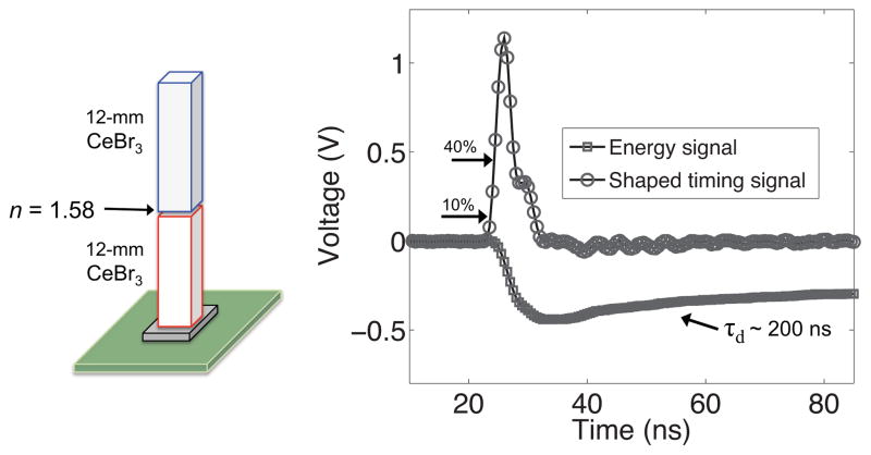
A NUV-SiPM was used to readout several stacked crystal pairs: LaBr3(Ce:20%) on CeBr3, both crystals 15-mm in length, and a pair of CeBr3 crystals, each 12-mm long. Compared to measurements using a PMT, it is apparent that the SiPM’s response and front end signal shaping are now heavily influencing the resulting signal shape (see figure 9). No added signal processing was implemented for analysis of the SiPM signal, and thus the calculated signal decay constant is representative of the large intrinsic RC constant of the SiPM and transimpedance amplifier, and not the fast scintillation decay and depth-dependent changes in light transport. However rise time differences, between crystal layers, were observed using the SiPM. Side-on measurements, isolating interactions within the central depth of each crystal layer, were performed characterizing the SiPM rise time response in each layer. Optimization of the rise time discrimination metric was repeated for the SiPM signal shape, and was slightly changed from 10%–50%, to 10%–40%, improving DOI accuracy. Rise time discrimination for the most challenging crystal pair, two CeBr3 crystals stacked using a crystal-to-crystal coupling of n=1.58, is shown in figure 10. A DOI accuracy of 91.4% was measured, and this is very similar to results obtained with a PMT readout of the same crystal pair using only rise time discrimination: 91.2% (see table 2). A similar trend was seen with the LaBr3(Ce:20%) on CeBr3 crystal pair, with SiPM having slightly better rise time discrimination compared to the PMT.
Figure 9.
Schematic of the stacked CeBr3 crystal pair and a representative sampled waveform using the 4×4mm2 SiPM readout. Two shaped signals are created, one for energy estimation (slow) and one for timing (fast). Rise time discrimination is based off of the shaped timing signal.
Figure 10.
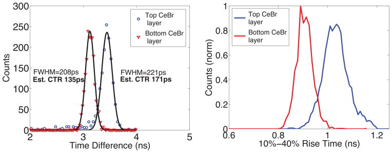
Layer timing resolution and rise time discrimination of the CeBr on CeBr crystal pair (illustrated in figure 9), from two side-on measurements. The layers are well separated and a DOI accuracy of 91.4% was measured. The shaped timing signal was used for rise time discrimination.
3.3.2 Effect of SiPM saturation
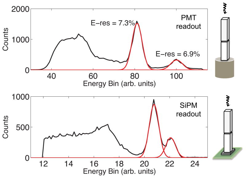
Energy saturation in the SiPM signal can be significant with high light output scintillators such as CeBr3 and LaBr3 and is evident in our measurements, as shown in figure 11. Here, energy spectra from a PMT and SiPM readout of the CeBr3 on CeBr3 crystal pair are shown together for comparison—no saturation correction was applied to the SiPM energy response. There is a reduction in photopeak separation between the top and bottom CeBr3 layers when read out using the SiPM, as well as an artificial improvement in energy resolution. Though saturation is compressing the SiPM energy response, the photopeak positions of both layers are still well separated from Compton scatter events, suggesting the SiPM readout should not degrade commonly used scatter correction techniques for PET imaging. The SiPM’s energy saturation, causing the partial overlap in the layer photopeak positions, will not degrade DOI accuracy because the DOI is determined based on the signal shape.
Figure 11.
The energy response from stacked CeBr3 crystals using a PMT readout (top) and a SiPM readout (bottom). Note the SiPM saturation greatly reduces the difference in photopeak separation between the top and bottom layers.
3.3.3 Timing resolution comparison
The timing resolution was also measured using the NUV-SiPM readout for the LaBr3(Ce:20%) on CeBr3 crystal pair and for the CeBr3 on CeBr3 crystal pair (both crystal pairs use coupling n=1.58). The LaBr3(Ce:20%) on CeBr3 crystal pair (30-mm total in length) had an estimated CTR of 229 ps and 176 ps, for the top and bottom layers. This was improved in the CeBr3 on CeBr3 crystal pair (24-mm total in length) to an estimated CTR of 171 ps and 135 ps, for the top and bottom layers, shown in figure 10. CTR results with the SiPM were better than results using a PMT for all comparison measurements. That said, the layer-to-layer degradations in timing resolution are of similar magnitude, and are caused by the slowing of the signal shape—the improvement in CTR of stacked crystal pairs with the SiPM is in part due to the better CTR with the crystals individually coupled. A comprehensive list of signal characteristics and measured CTR are presented in table 3.
Table 3.
Summary of energy and timing results for select crystal pairs investigated.
| Scintillator pair | Integrated Energy at 511 keV (ns* V) | Energy Resolution at 511 keV | Measured CTR (ps) on PMT | Measured CTR (ps) on SiPM |
|---|---|---|---|---|
| 5-mm CeBr, | 108 | 5.9% | 120 | - |
| 5-mm LaBr(20%) | 127 | 4.5% | 135 | |
| 15-mm CeBr, | 78 | 6.5% | 200 | 176 |
| 15-mm LaBr(20%) | 72 | 5.5% | 256 | 229 |
| 12-mm CeBr, | 99 | 6.9% | 176 | 135 |
| 12-mm CeBr | 81 | 7.3% | 222 | 171 |
| 30-mm CeBr* | 70 | 6.1% | 225 | 209 |
For comparison with a single, 30-mm long crystal
4. Discussion
We have shown that for a detector design based on stacked crystal layers, by controlling the crystal length and coupling material’s index of refraction we can adjust the layer-to-layer differences signal properties, in addition to using scintillators having different intrinsic Ce3+ concentrations. This allows detector designs to be constructed using the same scintillator in both layers, and we have shown that this is feasible for high Ce3+ doped scintillators and CeBr3. Multilayer DOI detectors based on the same scintillator type simplify the detector design, as only a single scintillation material must be grown, removing the DOI dependence from the scintillator, where signal properties can fluctuate between productions, to a more manageable situation where the crystal coupling and crystal length are controlled. The ability to use the same scintillation material in both crystal layers also maximizes the achievable timing resolution of the design, as the fastest scintillator can be used in both layers. From measurements with two identical crystals stacked and read out using a PMT, we have observed a layer-dependent change in signal rise time and signal decay constant and shown that using the information in both improves DOI accuracy. Though the SiPM distorts the scintillation pulse shape, layer-dependent differences in signal rise time are still detectable, but not differences in the signal fall time; future work using the SiPM readout will focus on methodology to extract this information.
CTR results with stacked crystals readout using a SiPM are very good—a tribute to the rapid development of SiPM technology and improved performance of the SiPM sensor itself—and for the first time in our lab, produce better timing results compared to using a fast, single channel PMT. It is important to note that the relative degradation in timing resolution, when going from the crystals individually coupled to their use in a stacked geometry, is very similar for results with a PMT and a SiPM. The slowing of rise time and decay constant are inevitable because of the added crystal-to-crystal interface and increased effective length. Measurements with a PMT allow the relative change in signal characteristics to be quantified. Using equation 1, the estimated degradation in CTR can be calculated by comparing light collection, signal rise time and decay time, from crystals individually coupled and then stacked—the estimate is very close to the measured CTR. For example, analyzing the data from the 15-mm long LaBr3(Ce:20%) crystal, individually coupled versus stacked on top of a CeBr3 crystal, the stacked rise time and decay constant are ~60% and ~20% longer, and light collection is reduced by ~40%. This would correspond to a ~55% increase in timing uncertainty (eq. 1) and we measure an increase of 61% (158ps / 256ps).
Several other generalizations can be made using equation 1 for DOI techniques based on discriminating the signal rise time, signal decay time (phoswich), or both (this work). Phoswich designs typically use scintillators with a factor of two difference in decay constant (Eriksson et al 2009), which alone would cause a ~40% increase in timing uncertainty for the layer with the longer decay time, in addition to degradations caused by slowing the signal rise time and a reduction in light collection—both of which are an unavoidable consequence of the stacked crystal geometry. This work suggests that the best TOF-DOI capability is achieved when the change in DOI signal shape is small, preserving the fast non-DOI signal shape. As seen in figure 6, the layer-dependent differences in signal shape are noticeable but subtle, and signal shapes from both layers retain their fast rising edge and short decay time. Though the signal metrics developed in this work perform well, they may not be optimal, and future work will focus on improving methods for signal shape discrimination. Waveform sampling plays an integral part in this process, as the maximum amount of information (the entire pulse shape) is captured, which should lead to optimal DOI discrimination methods. Once these signal discrimination metrics are found, they can easily be applied to waveform sampling data acquisition systems (Ashmanskas et al 2014). Pulse shape discrimination techniques can also be applied using analog shaping electronics (Saoudi et al 1999, Schmand et al 1999), which may be easier to implement in a large-scale application.
The sampling rate used for data acquisition is an important parameter. For the R4998 PMT readout, where the estimated analog bandwidth of the scintillation pulse and PMT response is ~1GHz, waveform sampling at 2 Gs/sec satisfies the Nyquist criteria, guaranteeing an aliasing-free reconstruction of the signal. It is difficult to know the rise time response of the SiPM, because of the energy dependent response and timing circuit used, however we believe it may be faster than the R4998 PMT. If the SiPM signal does contain components with a bandwidth faster than 1 GHz, waveform sampling at 2 Gs/sec could degrade rise time discrimination. Future work will examine the relationship between sampling rate and rise time discrimination. Signal saturation may be degrading rise time discrimination as well, and a new high-density NUV-SiPM design, a concept developed for other SiPMs (Piemonte et al 2013), may also improve rise time discrimination.
In conclusion, we would like to address how the results presented in this paper translate to a large-area detector design that could be used for whole-body PET. We have performed Monte Carlo simulations to calculate the probability of inter-layer scattering (Compton scatter within the detector block where energy is deposited in both scintillator layers). We estimate that for a detector block, 5 × 5 cm2 in area, composed of stacked arrays of CeBr3 crystals, each 15-mm long (30-mm total), about 18% of events will deposit energy in both layers. For these inter-layer scatter events, DOI discrimination will be compromised—ideally the layer having the first interaction would be identified. Considering the excellent DOI accuracy with individual pixels (almost 99% for LaBr3(Ce:20%) on CeBr3), at worst the DOI accuracy in a large-area detector block would be reduced to ~82%. Estimating the timing resolution of the large-area detector block must also include the probability of interacting in each layer and will depend on the photodetector used. We will continue to study this for detector designs based on PMT arrays. For detector designs using SiPMs having 1-to-1 coupling, no degradation in CTR is expected unless multiplexing methods are introduced.
5. Conclusions
Detector designs capable of measuring both TOF and DOI can be constructed using stacked scintillator approaches. We have shown that for LaBr3 and CeBr3 scintillators DOI can be encoded with very small changes to the non-DOI signal shape. Doing this preserves the inherently good timing properties of LaBr3 and CeBr3, creating a TOF-DOI detector design with minimal degradations and trade-offs. We have presented measurements quantifying the effects on optical transport caused by the stacked crystal interface, and shown that these can be large enough to create layer-dependent changes in signal shape when using CeBr3 in both crystal layers. Two, stacked CeBr3 crystals have an average timing resolution that is only minimally degraded, compared to a single CeBr3 crystal of equal overall length, but now contains DOI information within the signal shape. Results with two, stacked 12-mm long CeBr3 crystals, read out using a SiPM, show that a CTR of ~150 ps and a DOI accuracy of 91% can be simultaneously achieved based on this approach.
Acknowledgments
This work was supported by NIH grants R01 CA113941 and R21 EB016205. The authors would like to thank Radiation Monitoring Devices (Watertown, MA) for providing the crystal samples used in this work.
References
- Ashmanskas WJ, LeGeyt BC, Newcomer FM, Panetta JV, Ryan WA, Van Berg R, Wiener R, Karp JS. Waveform-Sampling electronics for a whole-body time-of-flight PET scanner. IEEE Trans Nucl Sci. 2014;61:1174–1181. doi: 10.1109/TNS.2014.2303119. [DOI] [PMC free article] [PubMed] [Google Scholar]
- Auffray E, Frisch B, Geraci F, Ghezzi A, Gundacker S, Hillemanns H, Jarron P, Meyer T, Paganoni M, Pauwels K, Pizzichemi M, Lecoq P. A comprehensive and systematic study of coincidence time resolution and light yield using scintillators of different size, wrapping and doping. IEEE Nucl Sci Symp Med Imag Conf Record. 2011:64–71. [Google Scholar]
- Bettinardi V, Presotto L, Rapisarda E, Picchio M, Gianolli L, Gilardi MC. Physical Performance of the new hybrid PET/CT Discovery-690. Med Phys. 2011;38:5394–5411. doi: 10.1118/1.3635220. [DOI] [PubMed] [Google Scholar]
- Cosentino L, Finocchiaro P, Pappalardo A, Garibaldi F. Characterization of a scintillating mini-detector for time-of-flight positron emission tomography with depth-of-interaction. Rev Sci Instru. 2012;83:1–10. doi: 10.1063/1.4739310. [DOI] [PubMed] [Google Scholar]
- Daube-Witherspoon ME, Surti S, Perkins AE, Kyba CCM, Wiener R, Karp JS. Imaging oerformance of a LaBr3-based time-of-flight PET scanner. Phys Med Biol. 2010;55:45–64. doi: 10.1088/0031-9155/55/1/004. [DOI] [PMC free article] [PubMed] [Google Scholar]
- Du H, Yang Y, Glodo J, Wu Y, Shah KS, Cherry SR. Continuous depth-of-interaction encoding using phosphor-coated scintillators. Phys Med Biol. 2009;54:1757–1771. doi: 10.1088/0031-9155/54/6/023. [DOI] [PMC free article] [PubMed] [Google Scholar]
- Eriksson L, Melcher CL, Eriksson M, Rothfuss H, Grazioso R, Aykac M. Design considerations of phoswich detectors for high resolution positron emission tomography. IEEE Trans Nucl Sci. 2009;56:182–188. [Google Scholar]
- Ferri A, Gola A, Serra N, Tarolli A, Zorzi N, Piemonte C. Performance of FBK high-density SiPM technology coupled to Ce:LYSO and Ce:GAGG for TOF-PET. Phys Med Biol. 2014;59:869–880. doi: 10.1088/0031-9155/59/4/869. [DOI] [PubMed] [Google Scholar]
- Glodo J, Moses WW, Higgins WM, van Loef EVD, Wong P, Derenzo SE, Weber MJ, Shah KS. Effects of Ce concentration on scintillation properties of LaBr3:Ce. IEEE Trans Nucl Sci. 2005;52:1805–1808. [Google Scholar]
- Gola A, Piemonte C, Tarolli A. Analog Circuit for timing measurements with large area SiPMs coupled to LYSO crystals. IEEE Trans Nucl Sci. 2013;60:1296–1302. [Google Scholar]
- Gundacker S, Knapitsch A, Auffray E, Jarron P, Meyer T, Lecoq P. Time resolution deterioration with increasing crystal length in a TOF-PET system. Nucl Instr Meth A. 2014;737:92–100. [Google Scholar]
- Jakoby BW, Bercier Y, Conti M, Casey ME, Bendriem B, Townsend DW. Physical and clinical performance of the mCT time-of-flight PET/CT scanner. Phys Med Biol. 2011;56:2375–2389. doi: 10.1088/0031-9155/56/8/004. [DOI] [PubMed] [Google Scholar]
- Kuhn A, Surti S, Karp JS, Raby PS, Shah KS, Perkins AE, Muehllehner G. Design of a Lanthanum Bromide detector for TOF PET. IEEE Trans Nucl Sci. 2004;51:2550–2557. [Google Scholar]
- Kyba CCM, Wiener R, Newcomer FM, Van Berg R, Dressnandt N, Karp JS. Timing measurements from a TOF-PET scanner using local PMT triggering. IEEE Nucl Sci Symp Med Imag Conf Record. 2007:4123–4128. [Google Scholar]
- Lecoq P, Auffray E, Brunner S, Hillemanns H, Jarron P, Knapitsch A, Meyer T, Powolny F. Factors influencing time resolution of scintillators and ways to improve them. IEEE Trans Nucl Sci. 2010;57:2411–2416. [Google Scholar]
- Liu S, An S, Li H, Wang C, Ramirez RA, Zhang Y, Baghaei H, Wong WH. A dual-layer TOF-DOI detector block for whole-body PET. IEEE Trans Nucl Sci. 2012;59:1805–1808. [Google Scholar]
- Moses WW, Derenzo SE. Prospects for Time-of-Flight PET using LSO scintillator. IEEE Trans Nucl Sci. 1999;46:473–478. [Google Scholar]
- Piemonte C, Ferri A, Gola A, Pro T, Serra N, Tarolli A, Zorzi N. Characterization of the first FBK high-density cell silicon photomultiplier technology. IEEE Trans Electron Devices. 2013;60:2567–2573. [Google Scholar]
- Pro T, Ferri A, Gola A, Serra N, Tarolli A, Zorzi N, Piemonte C. New developments of Near-UV SiPMs at FBK. IEEE Trans Nucl Sci. 2013;60:2247–2253. [Google Scholar]
- Quarati FGA, Dorenbos P, van der Biezen J, Owens A, Selle M, Parthier L, Schotanus P. Scintillation and detection characteristics of high-sensitivity CeBr3 gamma-ray spectrometers. Nucl Instr Meth A. 2013;729:596–604. [Google Scholar]
- Roncali E, Cherry SR. Application of silicon photomultipliers to Positron Emission Tomography. Annals of Biomed Eng. 2011;39:1358–1377. doi: 10.1007/s10439-011-0266-9. [DOI] [PMC free article] [PubMed] [Google Scholar]
- Roncali E, Phipps JE, Marcu L, Cherry SR. Pulse shape discrimination and classification methods for continuous depth of interaction encoding PET detectors. Phys Med Biol. 2012;57:6571–6585. doi: 10.1088/0031-9155/57/20/6571. [DOI] [PMC free article] [PubMed] [Google Scholar]
- Saoudi A, Pepin CM, Dion F, Bentourkia M, Lecomte R, Andreaco M, Casey M, Nutt R, Dautet H. Investigation of depth-of-interaction by pulse shape discrimination in multicrystal detectors read out by avalanche photodiodes. IEEE Trans Nucl Sci. 1999;46:462–467. [Google Scholar]
- Schaart DR, van Dam HT, Seifert S, Vinke R, Dendooven P, Lohner H, Beekman FJ. A novel, SiPM-array-based, monolithic scintillator detector for PET. Phys Med Biol. 2009;54:3501–3512. doi: 10.1088/0031-9155/54/11/015. [DOI] [PubMed] [Google Scholar]
- Schmall JP, Roncali E, Berg E, Viswanath V, Du J, Cherry SR. Timing properties of phosphor-coated polished LSO crystals. Phys Med Biol. 2014;59:N139–N151. doi: 10.1088/0031-9155/59/15/N139. [DOI] [PubMed] [Google Scholar]
- Schmand M, Eriksson L, Casey ME, Wienhard K, Flugge G, Nutt R. Advantages using pulse shape discrimination to assign the depth of interaction information (DOI) from a multi layer phoswich detector. IEEE Trans Nucl Sci. 1999;46:985–990. [Google Scholar]
- Shao Y. A new timing model for calculating the intrinsic timing resolution of a scintillator detector. Phys Med Biol. 2007;52:1103–1117. doi: 10.1088/0031-9155/52/4/016. [DOI] [PubMed] [Google Scholar]
- Shah KS, Glodo J, Klugerman M, Moses WW, Derenzo SE, Weber MJ. LaBr3:Ce scintillators for gamma-ray spectroscopy. IEEE Trans Nucl Sci. 2003;50:2410–2413. [Google Scholar]
- Shah KS, Glodo J, Higgins W, van Loef EVD, Moses WW, Derenzo SE, Weber MJ. CeBr scintillators for gamma-ray spectroscopy. IEEE Nucl Sci Symp Med Imag Conf Record. 2004:4278–4281. [Google Scholar]
- Shibuya K, Nishikido F, Tsuda T, Kobayashi T, Lam C, Yamaya T, Yoshida E, Inadama N, Murayama H. Timing resolution improvement using DOI information in a four-layer scintillation detector for TOF-PET. Nucl Instr Meth A. 2008;593:572–577. [Google Scholar]
- Spanoudaki VC, Levin CS. Investigating the temporal resolution limits of scintillation detection from pixellated elements: comparison between experiment and simulation. Phys Med Biol. 2011;56:735–756. doi: 10.1088/0031-9155/56/3/013. [DOI] [PubMed] [Google Scholar]
- Surti S, Kuhn A, Wener ME, Perkins AE, Kolthammer J, Karp JS. Performance of Philips Gemini TF PET/CT scanner with special consideration for its time-of-flight imaging capabilities. J Nucl Med. 2007;48:471–480. [PubMed] [Google Scholar]
- Surti S, Shore AR, Karp JS. Design study of a whole-body PET scanner with improved spatial and timing resolution. IEEE Trans Nucl Sci. 2013;60:3220–3226. doi: 10.1109/TNS.2013.2265605. [DOI] [PMC free article] [PubMed] [Google Scholar]
- Thoen H, Keereman V, Mollet P, Van Holen R, Vandenberghe Influence of detector pixel size, TOF resolutionvand DOI on image quality in MR-compatiblev whole-body PET. Phys Med Biol. 2013;58:6459–6479. doi: 10.1088/0031-9155/58/18/6459. [DOI] [PubMed] [Google Scholar]
- van Dam HT, Seifert S, Drozdowski W, Dorenbos P, Schaart DR. Optical absorption length, scattering length, and refractive index of LaBr3:Ce3+ IEEE Trans Nucl Sci. 2012;59:656–664. [Google Scholar]
- van Loef EVD, Dorenbos P, van Eijk CWE, Kramer K, Gudel HU. High-energy-resolution scintillator: Ce3+ activated LaBr3. Applied Phys Letters. 2001;79:1573– 1575. [Google Scholar]
- Wiener R, Kaul M, Surti S, Karp JS. Signal analysis for improved timing resolution with scintillation detectors for TOF PET imaging. IEEE Nucl Sci Symp Med Imag Conf Record. 2010:1991–1995. [Google Scholar]
- Wiener R, Surti S, Karp JS. DOI determination by rise time discrimination in single-ended readout for TOF PET imaging. IEEE Trans Nucl Sci. 2013;60:1478–1486. doi: 10.1109/tns.2013.2243166. [DOI] [PMC free article] [PubMed] [Google Scholar]
- Yeom JY, Vinke R, Levin CS. Side readout of long scintillation crystal elements with digital SiPM for TOF-DOI PET. Med Phys. 2014;41:122501–122509. doi: 10.1118/1.4901524. [DOI] [PMC free article] [PubMed] [Google Scholar]


