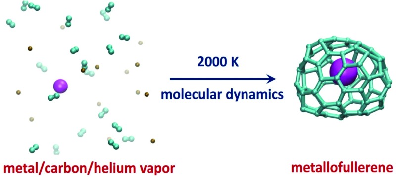
 Molecular dynamics simulations of the endohedral metallofullerene formation reveal a crucial role of the cooling gas (He) and the strength of metal–carbon bonding in the formation mechanism.
Abstract
The endohedral metallofullerene (EMF) self-assembly process in Sc/carbon vapor in the presence and absence of an inert cooling gas (helium) is systematically investigated using quantum chemical molecular dynamics simulations. It is revealed that the presence of He atoms accelerates the formation of pentagons and hexagons and reduces the size of the self-assembled carbon cages in comparison with analogous He-free simulations. As a result, the Sc/C/He system simulations produce a larger number of successful trajectories (i.e. leading to Sc-EMFs) with more realistic cage-size distribution than simulations of the Sc/C system. The main Sc encapsulation mechanism involves nucleation of several hexagons and pentagons with Sc atoms already at the early stages of carbon vapor condensation. In such proto-cages, both Sc–C σ-bonds and coordination bonds between Sc atoms and the π-system of the carbon network are present. Sc atoms are thus rather labile and can move along the carbon network, but the overall bonding is sufficiently strong to prevent dissociation even at temperatures around 2000 kelvin. Further growth of the fullerene cage results in the encapsulation of one or two Sc atoms within the fullerene. In agreement with experimental studies, an extension of the simulations to Fe and Ti as the metal component showed that Fe-EMFs are not formed at all, whereas Ti is prone to form Ti-EMFs with small cage sizes, including Ti@C28-T d and Ti@C30-C 2v(3).
Introduction
Since the discovery of fullerenes in 1985,1 scientists have been intrigued by the efficiency with which C60 and other fullerenes form during carbon vapor condensation, and have sought to explain this process. Somewhat surprisingly, there is still no generally accepted mechanism of fullerene formation in the research community, and even less is known concerning the formation of endohedral metallofullerenes (EMFs). A number of experimental (mainly mass-spectrometric) studies aimed at the clarification of the empty and endohedral fullerene formation have been performed,2–14 but it is not straightforward to design an experiment that could directly provide evidence for any of the debated mechanisms. The detection of the species formed during the laser ablation usually takes place a rather long time after the evaporation procedure, and therefore spectroscopic data represent more or less thermodynamic products and are not able to shed light on the early stages of the fullerene formation. The atomistic description of the fullerene formation was therefore addressed in many computational studies, which often involved molecular dynamics (MD) simulations of the hot carbon vapor or static first principles calculations of the cages of increasing size.3–5,8,10–12,15–30 MD simulations necessarily involve propagation of the polyatomic systems over a time scale of at least hundred picoseconds (and preferably longer) and hence are inevitably limited to classical or semi-classical computational methods, such as Brenner potentials and various flavors of tight binding approximations.
Over the last decade, Morokuma, Irle, and coworkers have performed extensive quantum chemical molecular dynamics (QM/MD) simulations31–38 based on density-functional based tight-binding (DFTB)1,39–42 simulations to reveal the formation mechanisms of fullerenes, nanotubes and graphene. In the studies of fullerene formation, the simulations usually were performed starting from an atmosphere of carbon dimers (C2 units) placed inside a cubic box with periodic boundary conditions, typically leading to a formation of giant fullerenes. Post annealing simulations revealed the possibility of shrinking such giant cages to smaller ones. Based on these simulations, a “Shrinking Hot Giant (SHG)” road of fullerene formation was proposed. According to this SHG mechanism, giant fullerenes Cn with n > 80 self-assembled in a “size-up” process through irreversible autocatalytic reactions of polyyne chains and macrocycles. Such cages have a lot of defects and unsaturated carbon chains. A “size-down” process of cage size shrinking dominated by a ‘fall-off’ of exohedral carbon chains and ‘pop-out’ of C2 units was observed in subsequent annealing simulations without periodic boundary conditions.33 However, regular, defect-free cages have not been produced so far in such simulations since with the healing of the defects the cages become kinetically more stable43 and rearrangement of the cage structure or loss of C2 becomes a rare event, requiring long simulation times. There was also no explicit consideration of the cooling gas during the fullerene formation, although the presence of He had been crucial for the discovery of fullerenes in the laser ablation of graphite,1 and its optimized pressure is of paramount importance for the arc-discharge synthesis of fullerenes. The presence of helium or argon was considered in fullerene growth and shrinking simulations by Saha et al. 38 In those studies it was shown that, depending on the carbon concentration in simulation boxes with periodic boundary conditions, the fullerene cages can either grow (high external carbon concentration) or shrink (low external carbon concentration).
The explicit use of He in tight binding MD simulations of fullerene formation has also been made by Laszlo.20 The temperature of the He gas was controlled by using a Nosé–Hoover thermostat, whereas the carbon gas was equilibrated via interactions with He atoms. In this process, reasonable cage structures were obtained from 60 carbon atoms at 2000 K. However, it remains unclear how the system would evolve if more or less carbon atoms were used in the simulations.
The mechanism of endohedral metallofullerene formation is even less understood than that of the empty fullerenes. In addition to the carbon cage formation, the role of the metal in the fullerene growth and the mechanism of the metal encapsulations needs to be clarified. Besides, one has to understand why certain conditions preferably lead to mono- and dimetallofullerenes, while different clusterfullerenes can be formed under other conditions.44–46 E.g., considering a pure metal–carbon system, the formation mechanism of mono-, di-, tri-metallofullerenes and metal carbide clusterfullerenes should be understood. Molecular dynamics simulations of EMF formation at 3000 K were performed by Maruyama and Yamaguchi using Brenner's classical potentials augmented by potential functions derived from DFT calculations of small metal-containing clusters.3,18 For Sc, their simulations showed relatively weak influence of the metal on the fullerene formation mechanism. Sc preferred to be located on the edge of the growing cage and could slip into the cage just before its closure. On the other hand, La was shown to have a stronger influence on the fullerene growth by serving as a nucleation center. Cooling gas effects were not taken into account in these simulations.
In this work we report direct quantum chemical molecular dynamics (QM/MD) simulations of the early stages of the endohedral fullerene formation based on the DFTB approach, and verify key processes occurring in the trajectories using ab initio molecular dynamics. An explicit consideration of the cooling gas was not done in a majority of MD studies of the fullerene formation. The temperature of the system in such simulations is usually controlled by an MD thermostat which may mimic the role of the cooling gas to some extent. However, it remains unclear if such treatment is realistic or is a serious misconception.47 To clarify this question, the role of helium gas in the fullerene growth is analyzed via QM/MD simulations as an integral part of this work, using classical He–He and He–C potentials.
Model and computational methods
All QM/MD simulations were performed using the DFTB+ program.48 Energies and nuclear gradients for carbon species were evaluated using both traditional DFTB (sometimes also referred to as non-charge-consistent, NCC-DFTB)40,49 and self-charge-consistent41 (SCC) approximations of the DFTB method, in combination with a finite electronic temperature approach (T e = 5000 K). The SCC-DFTB method was found to be less reliable as will be discussed below, and so the majority of reported results are obtained with DFTB using mio-0-1 DFTB parameters for C–C interaction, trans 3d-0-1 parameters for Ti, Fe,50 and modified parameters for Sc–Sc and Sc–C.51 The interaction of He atoms with He, C, Sc, Ti, and Fe is described by the Lennard-Jones terms of the classical UFF force field.52,53
In each simulation, carbon (in the form of C2 units), scandium and helium atoms were randomly placed in a cubic periodic boundary box, whose size was chosen to keep the carbon density in the range of the experimental scale (1020–1021 cm–3). Initial velocities were assigned randomly in accordance with the Maxwell–Boltzmann distribution for T = 2000 K, and the temperature of the system was then kept around 2000 K using a Nosé–Hoover chain thermostat with a coupling constant of 500 cm–1. In the first series of simulations aimed at the understanding of the role of the cooling gas, 200 carbon atoms were placed inside the 80 × 80 × 80 Å3 box, the number of He atoms was 0, 100, 200, 300, or 500, and the number of Sc atoms was either 0 or 6. For each combination of C/Sc/He atoms, 10 independent simulations were performed propagating the system for at least 200 ps (i.e., totally 100 trajectories were studied). In the second series aimed at the detailed study of the Sc encapsulation mechanism, the number of C and He atoms was reduced to 100 and 50, respectively, the size of the box was 50 × 50 × 50 Å3, whereas the number of Sc atoms was kept at 6 to increase the probability of encapsulation; 10 trajectories were studied with these initial conditions.
For ab initio MD simulations, we used the projector augmented-wave (PAW) pseudopotential plane-wave method with an energy cutoff of 280 eV as implemented in the VASP program.54 The Perdew–Burke–Ernzerhof (PBE) functional was used for the exchange correlation term.55 A Nosé–Hoover NVT thermostat set at 2000 K similar to DFTB calculation, and the velocity Verlet algorithm with a time step of 1 fs were used to propagate the system. Molecular structures were visualized using the VMD package.56
Additional DFT computations were carried out using the PBE functional in the PRIRODA package.57–59 The basis sets were of TZ2P-quality {6s,3p,2d}/(11,6,2) for C, and SBK-type core effective potentials were used in conjunction with {5s,5p,4d}/(9,9,8) valence basis sets for Ti.
Results and discussion
Influence of He on the empty fullerene formation
From 100 trajectories studied with and without He atoms, many resulted in the formation of fullerene cages. In general, the mechanism of their formation is the same with and without He, and includes (1) formation and growth of polyyne chains from C2 units; (2) self-cyclization reactions to form large carbon rings when chains become longer than ∼10 carbon atoms; (3) ring condensation reactions to form large fused sp2-hybridized carbon network systems with increasing number of pentagons, hexagons, and heptagons; (4) formation of closed-cage structures (fullerenes) as the process evolves further. However, the presence of He in the system dramatically affects the rate of the process, the length of the polyyne chains and their lifetimes, and eventually the yield and the size of the produced fullerene cages.
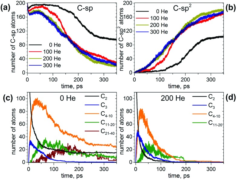
To describe the effect of the cooling gas in the fullerene formation process, first we analyze how the presence of He affects elementary steps of the formation mechanism. Fig. 1 compares the evolution of the number of C-sp and C-sp2 atoms in the MD simulations (C-sp is defined as carbon atom bonded with one or two other carbons, whereas C-sp2 is defined as carbon atom bonded to three other carbons). Obviously, the consumption of C-sp atoms in the presence of He is much faster. Whereas in He-free simulations roughly a half of all carbons are still in the C-sp state after 300 ps, the number is reduced to ca. 20% when He is introduced into the system. Likewise, the increase of the number of C-sp2 atoms is much faster in the presence of He. Variation of the number of He atoms from 100 to 300 does not lead to a significant difference over longer time scales (300 ps), although a noticeable deviation for a system with 100 He atoms is seen on shorter time scales (<150 ps).
Fig. 1. (a and b) Evolution of the number of (a) C-sp and (b) C-sp2 atoms during MD simulations of fullerene formation with different number of He atoms. (c and d) Evolution of the number of carbon atoms in C2 and C3 fragments and chains of different lengths (C4–C10, C11–C20, and C21–C40) in MD simulations without He (c) and in the presence of 200 He atoms (d). Each curve is averaged over 10 independent trajectories.
For an analysis of the carbon distribution between different chain structures, we chose simulations both without He and in the presence of 200 He atoms. Fig. 1c and d show evolution of individual C2 and C3 fragments as well as net values for free short chains (C4–C10), medium-size chains (C11–C20) and longer chains (C21–C40). In the absence of He, the number of C2 units decreases steeply during the first 70 ps, but then their abundance shows a tendency to level off near 10% all the way through 200–350 ps. The consumption of C2 units in the presence of He is much faster and is not levelling off, so that all C2 units are consumed already before 100 ps.
A bimolecular reaction between two C2 units results in a C4 chain, but such a reaction is exothermic and often leads to a dissociation of the product giving a C3 fragment and a single carbon atom. As a result, C3 units are the most abundant species after C2 at the short time scale, which agrees with their high concentration in hot carbon vapor.60 Reaching the maximum at ca. 6–8 ps (18% and 25% of all carbons in the absence and presence of He, respectively), the concentration of C3 fragments starts to decrease in favor of longer chains and reduces to negligible values at 150 ps in both types of simulations. Thus, the presence of He increases the number of C3 fragments at the maximum, but the overall time profiles are similar.
Starting from C4 and beyond, the presence of He leads to a faster formation of chains and their shorter lifetimes. The number of carbon atoms in C4–C10 chains reaches a maximum (ca. 40% of all carbons) at 15–25 ps, and then decreases exponentially until 180 ps. The fraction of carbons in longer chains increases to ca. 40 ps (the value at maximum is ca. 15%), remains in this range for next 30 ps, and then starts to decrease but not as steep as the fraction of the shorter chains. After 100 ps the average number of carbons in such chains is below 10, which means that in some of the simulations such chains already disappear, whereas in others 1 or 2 chains still remain. After 200 ps, all chains are consumed in the presence of 200 He atoms. In He-free simulations, the concentrations of shorter and longer chains reach their respective maximum at a similar time as with He, but their decay is then dramatically slower. Note also that the highest fraction of carbon in C4–C10 chains over the trajectories is ca. 50% (versus 40% in simulation with He). After 350 ps the fraction of carbons in C4–C10 chains is ca. 15%, and that of C11–C20 chains is ca. 4% (again, 1–2 chains in roughly half of trajectories). Beyond 250 ps, the systems seem to be stationary (i.e. no significant development). In the presence of He, we did not observe the formation of long chains (>20 atoms) in statistically meaningful amounts, but under He-free conditions such long chains were observed in several trajectories. The number of carbon atoms in such chains increases to ca. 150–200 ps, but then decays to negligible values after 350 ps.
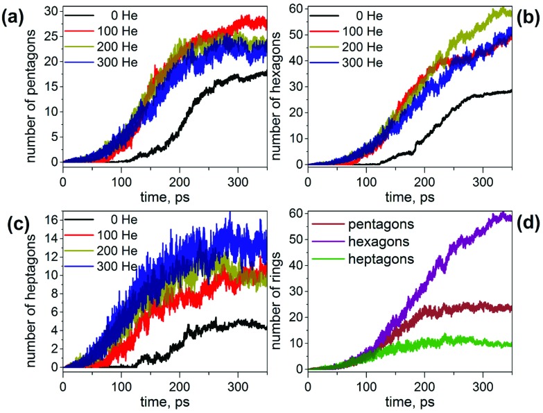
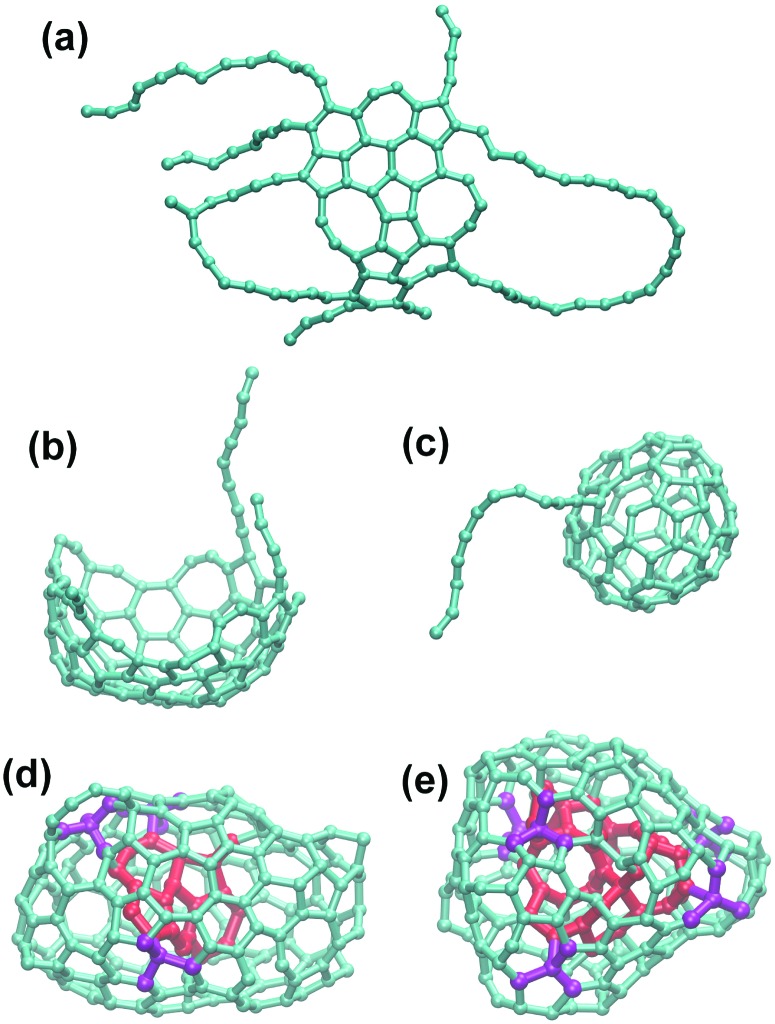
This analysis shows that the presence of He results in a faster evolution of carbon chains into carbon networks. Under conditions of our simulations, all free chains were formed and consumed during the first 200 ps. On the contrary, many carbon chains, including the long ones, survived after 350 ps in the absence of He. It should be noted that the statistics discussed above concern only free linear chains. We did not analyze large rings, branched chains or chains terminated on one side by bonding to carbon clusters because determination of their lengths is rather ambiguous. However, the principal effect of the cooling gas on chain length distribution is similar for these rings and chains as well.30,61,62 A faster formation of carbon networks in the presence of He can be exemplified by plotting the number of small carbon rings. The majority of the rings formed are pentagons, hexagons, and heptagons, and their number versus time is shown in Fig. 2. Under He-free conditions, the first C5–C7 rings appear after ca. 120 ps, whereas in the presence of He, 5–8 pentagons, 7–12 hexagons, and 3–7 heptagons are already formed at this moment. All curves show roughly a sigmoidal shape, and these curves are shifted by the presence of He towards a later time with an overall smaller number of rings at the “end” of trajectories. In particular, the sigmoidal growth of the number of pentagons levels off after ca. 220–250 ps with the formation of 23–27 pentagons in the presence of He and 18 rings under He-free conditions (the values are for 350 ps). The number of hexagons grows continuously in the presence of He up to ca. 50–60 rings at 350 ps, whereas under He-free conditions the number levels off after 300 ps near 28 rings. Finally, the number of heptagons reaches a maximum at ca. 250 ps, and then shows a sign of slow decrease. The number of heptagons formed under He-free conditions is roughly 3 times smaller than in the presence of He. The chain and ring statistics discussed above show that the presence of He significantly influences the conditions for fullerene formation and overall “improves” the probability of cage formation on our simulation time scales. Indeed, from 10 He-free trajectories, only 5 resulted in fullerene cages after 350 ps. In three others the process stopped at the nucleation stage, and two simulations produced half-cages with large diameters (Fig. 3). The fullerene cages formed in successful trajectories often have carbon chain “antennas” (Fig. 3). At 0 He pressure, in most cases we observed only one nucleation center, which slowly grows by absorbing long chains (which can also have long lifetimes).
Fig. 2. (a–c) Evolution of the number of (a) pentagons, (b) hexagons, and (c) heptagons formed during MD simulations of the fullerene formation with different number of He atoms; (d) number of pentagons, hexagons, and heptagons formed in simulation with 200 He atoms. Each curve is averaged over 10 independent trajectories.
Fig. 3. (a–c) Examples of the carbon clusters obtained under He-free conditions: (a) “flake”, (b) half-cage; (c) fullerene cage with carbon chain “antenna”. (d and e) Typical structures with endohedral carbons obtained at high He pressure: 300 He (d) and 500 He (e). Endohedral carbon atoms are colored in red, whereas four-coordinated carbon and their neighbors are shown in purple. Note that the structure obtained with 500 He is more compact (has less empty space) than the structure obtained with 300 He atoms.
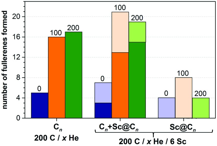
The situation changes dramatically when He is introduced into the system. With 100 and 200 He atoms, each trajectory resulted in fullerene cages (thus, the fullerene yield is increased dramatically as can be seen in Fig. 4). Most of the self-assembled cages were free of carbon chain “antennas”. Moreover, in more than half of the simulations two cages were formed in one trajectory (and some of them coalesced after formation to produce a larger cage). Thus, in the presence of He gas fullerenes are formed faster, and they are smaller at the initial stages. A plausible explanation of this behavior is that the carbon diffusion is slowed down by He atoms. The carbon vapor has more relaxation time to form a reasonable size of condensation for sp2-hybridized nuclei, which finally form fullerenes of more regular, smaller sizes. The progress of the nucleation stage is also considerably altered in the presence of He. In He-free trajectories, a typical scenario is the formation of one large and relatively flat carbon flake, which is rather stable kinetically and often does not transform into the cage structures (hence high degree of trajectories not leading to fullerenes; note that in some cases high stability of flakes is caused by formation of infinite ribbons due to the periodic boundary conditions). In the presence of He, faster nucleation results in the concurrent formation of two–three nucleation centers. Large flat flakes are thus not formed as they curl up into more compact structures at earlier stages, hence leading to a faster growth of smaller cages (C40–C80).
Fig. 4. Comparison of the number of produced fullerenes in 10 trajectories with different number of He atoms (0, 100, and 200) and with/without 6 Sc atoms. For trajectories with Sc atoms, the yield of Sc-EMF is shown separately (rightmost columns) as well as together with empty cages (columns in the middle).
Such cages have many defects and tend to grow further via absorption of carbon chains and coalescence of two small cages into larger ones. The latter process is probably less feasible in real arc-discharge synthesis, when the carbon vapor is expanding adiabatically and the density of carbon vapor becomes lower over time, thereby reducing the probability of cage fusion. Note however that fusion of fullerene cages was observed in collision experiments.13,63–65
When 300 He atoms were used in the MD simulation, a similar high yield of fullerene formation was observed. However, in several trajectories we found the structures comprising endohedral carbon clusters with an increased number of four-coordinated carbon atoms (Fig. 3d). To clarify if this can be an effect of the high He pressure, an additional series of simulations was performed with the number of He atoms in the box increased to 500. With such a large number of He atoms, all 10 trajectories produced “droplets” of amorphous carbon (see Fig. 3e for an example), proving that the high pressure of the cooling gas has a deteriorating effect on the fullerene formation. This means that under high He pressure the carbon clusters tend to be as compact as possible, and such amorphous agglomerates have a smaller volume than the hollow-caged fullerenes. It is likely that the particles formed under such extreme conditions may be further annealed to nanodiamonds or carbon onions as they are normally produced with higher gas pressure than fullerenes or even in liquids,66–71 however further exploration of such structures is beyond the goal of this work. Thus, in agreement with experimental studies, our results show that fullerenes are efficiently formed in a certain interval of He pressures. Too low or too high pressure reduces the yield, albeit via different mechanisms. Interestingly, and remarkably, none of the simulations produced He inside the cages. He diffusion occurs on much faster time scales.
Sc endohedral fullerene formation
Sc-EMFs under He-free conditions
MD simulations performed in the presence of 6 Sc atoms showed that the metal imposes a considerable influence on the process efficiency under He-free conditions. From ten trajectories, only one failed to produce a fullerene (versus 5 “failed” trajectories without Sc). Five trajectories resulted in Sc-encapsulated monometallo-fullerenes and four gave empty fullerenes. In two cases we observed the formation of “networked” Sc fullerenes (i.e. with Sc substituting a carbon atom in the sp2 carbon cage network). Thus, under He-free conditions, the presence of Sc atoms significantly increases the yield of fullerene structures.
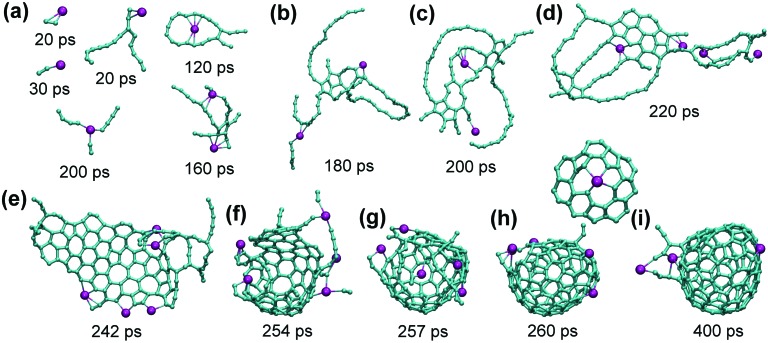
Analysis of the trajectories shows that Sc atoms form multiple Sc–C bonds at all stages of the fullerene formation. At the beginning, Sc coordinates to C2 units and longer carbon chains. When carbon chains start to nucleate and develop into polyaromatic flakes, Sc atoms bond to the free valencies at their perimeters as illustrated in Fig. 5. This bonding is strong enough to prevent dissociation even at 2000 K, but is still rather labile so that Sc atoms typically move along the perimeter from one bonding site to another as well as along the surface of the flake. Such Sc atoms also easily bond to free carbon chains and hence can also serve for a faster transfer of additional carbon to the growing cages. Presumably, coordination of Sc induces faster curling of such flat flakes into cages (Fig. 5), which may be a reason for the catalytic activity of Sc in the fullerene formation. Namely, bonding of a carbon atom to Sc weakens its bonds to neighboring carbons, thus facilitating local transformations in the carbon network. When cage-like structures with large holes and numerous dangling bonds are formed at first, Sc atoms bind to such edges and remain there all the way through the cage formation. Whether Sc atoms are trapped inside or left outside the cage after its closure is more or less random. In rare cases, the structures can be stabilized also in a “networked” cage as shown in Fig. 5i. Note that exohedral bonding of Sc to the cage is weak and has very short-lifetime under the conditions of our simulation (2000 K).
Fig. 5. (a) Bonding of Sc to small carbon clusters at different moments of the trajectory under He-free conditions: two Sc–C2 fragments, bonding to carbon chain, carbon ring, simultaneous bonding to C2 and two C4 fragments, and bonding to an early nucleation center. (b–e) Development of the flake from nucleation center, (e–h) curling of the flake up into a fullerene cage. (i) The “final” cage after additional 140 ps annealing. Note that Sc atom in (f) is bonded to the forming cage and simultaneously to C2 and longer chains. Also shown above (h) and (i) is the “networked” Sc atom in the place of a carbon atom in the fullerene cage: this fragment was formed near 260 ps and survived till the end of simulation at 400 ps.
Sc-EMF formation in the presence of He
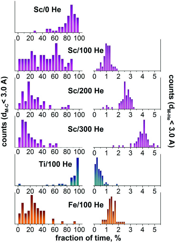
The presence of He has an ambivalent effect on the Sc-EMF formation. Addition of 100 He atoms doubles the yield of EMFs in comparison with He-free conditions (Fig. 6), but in the presence of 200 He atoms the yield is dropped back (although the yield of empty fullerenes remains high). The main reason for the negative influence of a higher He pressure is breaking of Sc–C bonds by collisions with He atoms. This can be illustrated by studying the time when a metal atom has at least one carbon at the distance closer than 3 Å. The histogram in Fig. 6 shows that under He-free conditions, the majority of Sc atoms are bound to carbon atoms most of the time (the distribution peaks at 80–90%). A completely different pattern is observed in the presence of 100 He atoms. The equivalent distribution becomes rather diffuse with almost equal values all over the 0–90% range. Note that the longer times are dominated by endohedral Sc atoms since they always have carbon atoms at short distances. Increasing the number of He atoms in the system increases the frequency of collisions with He atoms and dramatically decreases the Sc–C bond lifetime: the maxima of distributions are found at 20% and 10% for 200 and 300 He atoms, respectively (Fig. 6).
Fig. 6. Left: the fraction of time when the metal atom has at least one carbon atom at the distance shorter than 3 Å. Each histogram is based on 60 values obtained after analysis of 10 trajectories in 80 × 80 × 80 Å3 box with 200 C atoms, 6 metal atoms (Sc, Ti, or Fe), and indicated number of He atoms (0, 100, 200, or 300). Right: the same for metal–He distance shorter than 3 Å. In effect, the left column describes the net lifetime of metal–carbon bonds, whereas the right column visualizes the frequency of metal–He collisions. Note that when a metal atom is encapsulated in the fullerene, it always has carbon atoms at short distances and at the same time it is shielded from He atoms.
Another reason for lower yields of Sc-EMFs with increasing He pressure is the faster formation of fullerenes. A relatively slow nucleation and formation of extended kinetically stable flakes under He free conditions give the system sufficient time to gather several Sc atoms in the growing cage. Although not all He-free trajectories with Sc ended up with endohedral fullerenes, Sc atoms were covalently bound to all growing fullerenes. With He atoms in the system, nucleation and fullerene growth are faster and often avoid the formation of large flakes such as shown in Fig. 5e. Under the conditions of the concurrent formation of 2–3 cages, some of the fullerenes were formed before they had a chance to “meet” any Sc atom. Whereas with 100 He atoms we still could observe the formation of flattened and rather long-lived flakes in several trajectories (which were then coordinated by Sc atoms and sometimes resulted in EMF formation), with 200 He atoms in the system such intermediates were not observed at all.
We conclude that in the presence of He, Sc has no dramatic effect on the fullerene formation mechanism, i.e. the formation of the carbon cage follows a similar mechanism for both empty and endohedral fullerenes. The propensity of Sc atoms to form metal–carbon bonds leads to a coordination of Sc atoms to free valences of growing carbon cages, which may eventually result in the encapsulation of Sc and the formation of the EMF molecule. Collisions with He decrease the Sc–C bond lifetime, and therefore the relative yield of Sc-EMFs to the empty cages decreases with the increase of the He pressure from 5 : 4 for He-free conditions to 10 : 13 for 100 He atoms and further to 4 : 20 for 200 He atoms (Fig. 4). Nonetheless, the highest absolute yield of Sc-EMFs is achieved with 100 He atoms, because a dramatic increase of the fullerene formation yield is able to compensate for the shortening of the Sc–C bond lifetime. A further increase of the He pressure, while preserving the high yield of empty fullerenes, reduces the probability of EMF formation. This result shows that the optimum He pressure can be different for the synthesis of empty and endohedral fullerenes.
The influence of metal/carbon ratio and carbon density
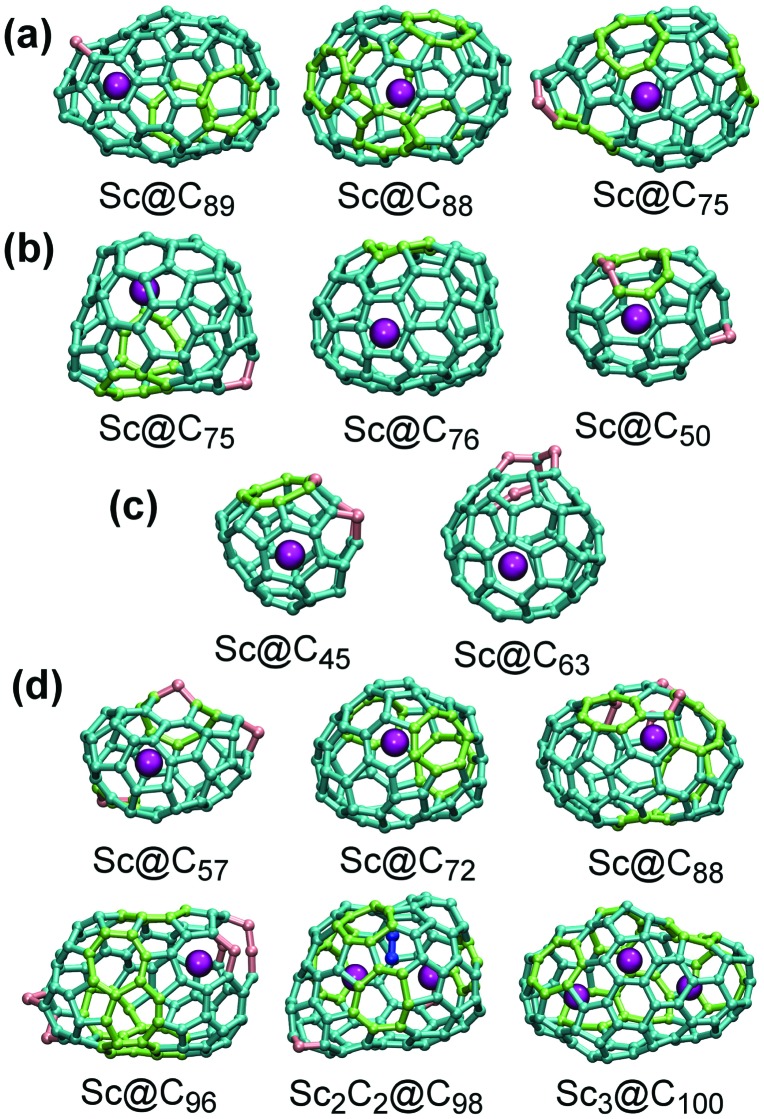
Having clarified the influence of He, we also studied how EMF formation is affected by the metal/carbon ratio and carbon density. First, we performed two series of MD simulations with the same size of the box (80 × 80 × 80 Å3), which contained 100 He atoms, 6 Sc atoms, and either 100 or 60 carbons (versus 200 carbon atoms discussed above). With 100 C atoms in the box, all trajectories resulted in the fullerene formation, however only two of them gave Sc-EMFs (Sc@C45 and Sc@C63, Fig. 7c). Whereas simulation with 200 C atoms usually resulted in 2–3 cages per trajectory, a two-fold decrease of the carbon density reduced the number of cages to one per trajectory (only once two small cages were formed). A further decrease of the carbon density to 60 atoms in the 80 × 80 × 80 Å3 box had a devastating impact on the fullerene formation: from ten trajectories, eight failed and two gave empty fullerenes.
Fig. 7. Examples of Sc-EMFs formed in MD simulation: (a) in the He-free 200 C/6 Sc system inside the 80 × 80 × 80 Å3 box; (b) in the 200 C/6 Sc/100 He system inside the 80 × 80 × 80 Å3 box; (c) in the 100 C/6 Sc/100 He system inside the 80 × 80 × 80 Å3 box; (d) in the 100 C/6 Sc/50 He system in the 50 × 50 × 50 Å3 box. Carbon atom and CC bonds are shown as cyan (pentagons and hexagon), light green (heptagon and other non-classical rings), or pink (carbene atoms). Endohedral carbons in Sc2C2@C98 are shown in blue.
A much higher EMF yield in the 100 C/6 Sc system was achieved when the system was placed in the box of the smaller size (50 × 50 × 50 Å3) and the number of He atoms in the smaller size box was reduced to 50. These conditions were found to be the most favorable for the EMF formation: eight trajectories ended up in the Sc monometallofullerenes, one resulted in trimetallofullerene Sc3@C100, and one resulted in the formation of the carbide clusterfullerene Sc2C2@C98 (Fig. 7). Importantly, in the smaller box each trajectory produced only one fullerene cage (instead of two–three cages for 200 C atoms in the larger box). Thus, a high Sc/C ratio increases the probability of the Sc encapsulation via increase of its density and effective increase of the probability of the Sc–C bonding.
Mechanism of Sc encapsulation
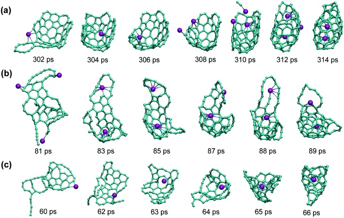
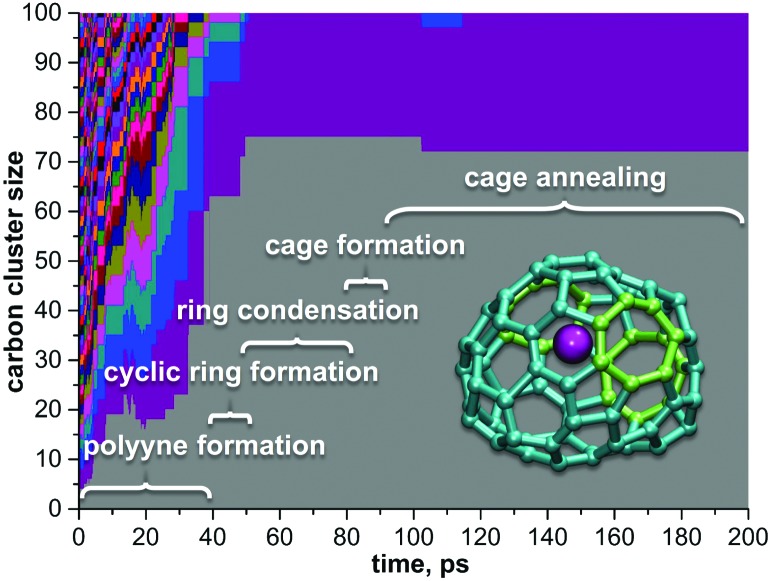
The successful formation of a series of Sc-EMFs in MD simulations allows us to analyze the mechanism of the Sc encapsulation during the Sc-EMF formation. Typical examples of the encapsulation process are shown in Fig. 8, and Fig. 9 is a sketch of the whole mechanism of the fullerene formation for Sc@C72 (the structure of this EMF is shown in Fig. 7d and the mechanism of Sc encapsulation is shown in Fig. 8b).
Fig. 8. Representative examples of the Sc encapsulation during the Sc-EMF formation: (a) 200 C/6 Sc/100 He system, the procedure resulted in dimetallofullerenes Sc2@C82 (an empty fullerene was also formed in this trajectory); three Sc atoms are coordinated to the growing cage just before its closure (310 ps), but only two of them are eventually encapsulated within the fullerene; (b) 100 C/6 Sc/50 He system; two Sc atoms were coordinated to the carbon cluster, but only one of them is eventually encapsulated; note that the cage after its closure is rather small and is fused to two large carbon rings, which are absorbed by the cage in the course of further annealing to make Sc@C72 (see also Fig. 7d and 9); (c) another trajectory from the 100 C/6 Sc/50 He system; the structure formed at 66 ps is highly defective Sc@C66, which then grew to Sc@C96 (see Fig. 7d) by capture of other carbon fragments.
Fig. 9. An overview of the Sc-EMF formation mechanism based on the trajectory, which resulted in Sc@C72. Detailed mechanism of the cage formation in this trajectory is shown in Fig. 8b. Each color field corresponds to the carbon cluster, its height scales as the number of carbon atoms: after 100 ps, only two clusters are left, Sc@C72 and C28.
As in the empty fullerene formation, the carbon cluster goes through the stages of polyyne chains, formation of rings and their further condensation with the formation of extended “flakes” (Fig. 9). The flake formation and its further dwelling in this kinetically stable state can be quite long (tens and even hundreds of picoseconds), but once the flake starts to curl up into the fullerene cage, the process then proceeds very fast and is usually fulfilled within few picoseconds (Fig. 8).
Since networked Sc was not found in simulation with He, we proposed that such a state can be stable only under He free conditions. To verify it, we used coordinates and velocities of carbon and Sc atoms from Fig. 5g and added 100 He atoms to the system (He temperature was also set to 2000 K) and followed 10 independent trajectories. After addition of He, the networked Sc survived for only a few picoseconds: in 7 trajectories it was pushed out of the cage, and in three trajectories formed endohedral fullerenes. Thus, we conclude that the stabilization of “networked” Sc fullerenes can take place only without He, and hence can hardly take place under real experimental conditions of the arc-discharge synthesis.
Importantly, all MD simulations discussed above were performed in the original DFTB formalism.40 The second generation of the DFTB method included self-consistent charge correction41 (SCC-DFTB) and was expected to be more applicable for the problems with inhomogeneous charge distribution such as EMF formation. However, our attempts to apply SCC-DFTB for the Sc-EMF formation always resulted in networked Sc-fullerenes which were then stable and infinitely long (>2 ns). The formation of endohedral fullerenes with a SCC-DFTB approach was not observed at all; instead, He atoms were often encapsulated with the fullerene cages. To clarify if DFTB or SCC-DFTB is more reliable for this system, we performed ab initio (DFT) MD simulation. In agreement with the DFTB results, DFT-based MD simulations showed that networked Sc-fullerenes are not very stable and encapsulation proceeded within one picosecond (see the ESI†). Thus, we propose that available SCC-DFTB potentials for Sc–C interactions overestimate stability of multiply Sc–C bonded Sc atoms and hence are not applicable for MD simulations of the EMF formation (at least, without re-parameterization).
Defects in formed cages
The fullerene cages formed in our MD studies within 200–400 ps had a number of defects, as can be seen in Fig. 7. The most common defects are heptagons (so far, only one EMF structure is known to have a heptagon,72 whereas all other structurally characterized EMFs consist of pentagons and hexagons) and carbene-type carbon atoms (i.e. carbon bonded to two other carbon atoms instead of three).
The presence of carbene carbons results in the odd number of carbon atoms in some EMF cages. Finally, the number of pentagon adjacencies is also rather large. Thus, the procedure developed in this work does not produce defect-free fullerene cages. Annealing at 2000 K is also not efficient for rearrangement, at least for heptagons. We conclude that the use of a Nosé–Hoover thermostat during annealing is not efficient since rearrangement in the carbon framework (such as Stone–Wales transformation) requires the local increase of kinetic energy, which is prevented by the thermostat. Since this work does not aim at the obtaining of defect-free carbon cages but is rather focused on the overall mechanism of the EMF formation and metal encapsulation, we did not pursue the question of the cage annealing further leaving it for future work.
Iron and titanium metallofullerenes
Iron/carbon system
To verify the validity of our computational approach, we have performed MD simulations for two other metals, Ti and Fe, using an 80 × 80 × 80 Å3 box, 200 carbons, 100 He atoms, and 6 metal atoms analogously to Sc runs. Under these conditions we did not observe the formation of Fe-encapsulated fullerenes. All ten trajectories resulted in the formation of empty cages. Behavior of Fe atoms during the fullerene formation was similar to that of Sc, i.e. Fe atoms also tended to form Fe–C bonds. However, these bonds are considerably weaker than the Sc–C bonds, which leads to a shorter Fe–C bond lifetime. This effect can be clearly seen in Fig. 6: the lifetime distribution for metal–carbon bonds in the Fe/100 He system is shifted to shorter lifetimes when compared to the Sc/100 He system and is similar to the Sc–C distribution in the system with 200 He atoms. This result points to an important role played by the metal–carbon bonding in the endohedral fullerene formation. This result is in perfect agreement with experimental data which did not show Fe-EMFs either in arc-discharge or in laser-ablation experiments.
Formation of Ti-EMFs
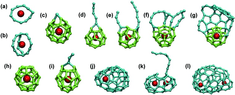
The importance of the strength of the metal–carbon bonding is further corroborated in the study of the Ti–C system. At the level of our DFTB simulations the Ti–C bonds appear to be much stronger than the Sc–C bonds, as can be clearly seen in the lifetime distribution histogram (Fig. 6). Ti atoms were coordinated to the carbon clusters at the early stages of their growth and, due to the strong Ti–C bonds, such agglomerates could not be broken by collision with He atoms. Furthermore, unlike almost innocent Sc atoms, Ti atoms played a role of “assembly points” for the fullerene cages, thus dramatically affecting the fullerene growth. Fig. 10 shows some intermediate Ti–carbon clusters detected at different stages of the trajectories. For instance, quite stable were the carbon rings with Ti atoms in the middle (for Sc, such rings were also observed, but they did not survive for a long time). Thus, Ti atoms templated the formation of small carbon cages around them. Quite a typical motif is Ti@C28-T d, the endohedral fullerene which was efficiently formed in laser-ablation experiments.15,73 We observed the formation of Ti@C28 in several trajectories, but usually this cage had some defect, such as single carbene-type atom inserted into the C–C bond, or a longer chain bonded to the cage, or a larger carbon flake fused to Ti@C28 (Fig. 10c–g). The small cages could then grow via an absorption of carbon fragments or fuse together forming di- and even tri-metallofullerenes. At the end, almost all Ti atoms formed EMFs, either small-to-medium size monometallofullerenes, or di- to tri-metallofullerenes with larger cage sizes (each trajectory produced 3–4 Ti-EMFs, whereas empty cages were not formed). Typical examples of larger cages and agglomerates are shown in Fig. 10j–l.
Fig. 10. Stable Ti–Cn clusters and EMFs formed in MD simulations: (a) Ti–C10 ring; (b) Ti@C16 proto-cage; (c–g) structures with common Ti@C28-T d motif with additional (c) carbon atom, (d) carbon chain, (e) two chains, (f) fused rings, and (g) fused “flake”; (h) defect-free Ti@C30-C 2v(3); (i) Ti@C30-C 2v(3) with an additional C3 chain; (j) Ti@C66; (k) small-cage di-Ti EMF with an additional carbon chain C9; (l) large-cage di-Ti EMF. In (c–i) fragments of regular Ti@C28 or Ti@C30 cages are shown in light green, all other carbon are shown in cyan color, Ti atoms are dark red.
To analyze how the system may develop under a smaller Ti/C ratio, the simulations were performed with only one Ti atom per 200 C atoms in the same box size. Ti-EMFs were not obtained only in two trajectories from ten: both afforded only empty fullerenes and the Ti atom coordinated to a small carbon cluster (a ring or a chain). Among eight Ti-EMFs formed in successful trajectories, two had a Ti@C 28-T d structure with attached chains, and one was Ti@C30-C 2v(3), also with an additional chain fragment. Medium to large size Ti@C2n EMFs were obtained in other runs; importantly, these EMFs also had smaller Ti-EMFs as their precursors. Thus, even in the presence of large excess of carbon, Ti is still prone to form small fullerenes, whose kinetic stability then depends on the regularity of the cage structure. Ti@C28 and Ti@C30 EMFs are rather stable, whereas intermediate structures with a large number of defects are more eager to capture additional carbon fragments and grow further.
To clarify if the formation of metallo-carbohedrene (met-car) structures such as experimentally observed Ti8C12 74–77 is also possible, simulations were performed with a large Ti/C ratio (100 Ti and 100 C atoms). We found that small to medium mixed titanium–carbon clusters (total size usually less than 20 atoms) are formed in such systems (Fig. S6†), but none of 20 trajectories produced Ti8C12. Optimization of the conditions (Ti/C ratio, pressure, temperature etc.) may be needed to simulate formation of met-cars, which goes beyond the scope of this work.
Formation mechanism of Ti@C30-C 2v(3)
Due to the smaller cage size, Ti-EMF cages produced in MD simulations have a smaller number of defects than Sc-EMFs. For instance, heptagons are rare for Ti-EMFs in our simulations, whereas they are quite common for Sc-EMF and empty fullerenes obtained in this work (Fig. 7). As already mentioned, Ti@C 28-T d motif is quite persistent and was formed in at least 5 out of 20 trajectories. In one trajectory we also observed the formation of the defect-free Ti@C30 EMF with a C 2v(3) cage isomer (Fig. 10h), which is also believed to be formed in the laser-ablation studies of the Ti/graphite system.15,73,78
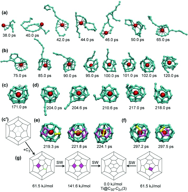
The growth of Ti@C30-C 2v(3) from the carbon vapor in MD simulations is depicted in Fig. 11. The process started with the coordination of a Ti atom to a branched C9 fragment at 38 ps (Fig. 11a). Over the next few picoseconds, the cluster grew further by absorbing additional carbon chains from the vapor. The cluster composition at this stage is rather labile, and carbon atoms can be equally likely absorbed and ejected. Thus, the number of carbon atoms in the cluster was 9 at 38 ps, 23 at 40 ps, 25 at 42 ps, then two carbons were lost at 46 ps, the cluster grew again to C25 at 48 ps, lost 4 carbons at 55 ps, then gained C2 at 65 ps, and finally stabilized its size at C27 after 75 ps. All the way from 38 to 75 ps the cluster can be described as a very labile conglomerate of branched medium-size chains, sporadically closing into carbon rings around Ti. After 75 ps, the chains started to condense into smaller rings (C4–C6) forming a proto-cage with the Ti atom in the center. Fig. 11b depicts how the C9 chain attached to the growing carbon cage is gradually “eaten” by the growing cage over the period of ca. 30 ps, till it is completely transformed to the cage-like structure after 100 ps. At this moment, although the small fullerene cage is already distinguishable, carbons still move with large amplitudes, which often results in breaking of CC bonds. E.g., a small fullerene structure is first observed at 120 ps, but complete stabilization is achieved ca. 50 picoseconds later. Fig. 11c shows the Ti@C27 cage formed as a result of this process (see also its Schlegel diagram in Fig. 11c′). The structure closely resembles the Ti@C28-T d EMF missing one carbon at the triple-pentagon junction, so that the cage has a large orifice. Due to its high kinetic stability, the Ti@C27 remained almost intact over the next 30 ps, till it absorbed a C3 fragment at 204 ps (Fig. 11d; note that at this moment only a few free carbon fragments are left, and hence such collisions are much rarer than during the first 70 picoseconds). Although initially attached to the site opposite to the “missing” carbon atom, the C3 chain then quickly (within few ps) migrated closer to the orifice, where it was ingested into the fullerene cage producing the Ti@C30 fullerene (Fig. 11e). Note that the mechanism of C3 capture shown in Fig. 11d is similar to the results of DFT and MD simulations for C2 addition to small Ti@C2n cages reported recently by Poblet et al. 15 The cage isomer formed at 219.3 ps had a defect, a four-membered ring. Quite rapidly, within next 2.5 ps, this isomer underwent a Stone–Wales (SW) transformation (pseudo-rotation of one C–C bond by ca. 90°) to form the second four-membered ring at 221.8 ps. Finally, within the next 2.3 ps, another Stone–Wales transformation took place producing the defect-free Ti@C30-C 2v(3) a 224.1 ps (Fig. 11e). Although the C 2v(3) isomer is the most thermodynamically stable form of Ti@C30, the newly-formed cage was still rather labile and transformed into the structure with defects from time to time. At 297.2 ps we again observed the formation of the Ti@C30 isomer with a four-membered ring. This isomer again produced Ti@C30-C 2v(3), but this time in a single SW step as depicted in Fig. 11f. For the sake of clarity, Fig. 11g also shows Schlegel diagrams of Ti@C30 isomers and their transformations observed in MD simulations.
Fig. 11. Mechanism of the Ti@C30-C 2v(3) formation in MD simulations. (a) Formation of the Ti–C9 cluster and its growth to Ti–C27; (b) condensation of long chains into the fullerene cage surrounding Ti atom; (c, c′) molecular structure and Schlegel diagram of Ti@C27 resembling Ti@C28-T d(1) with one atom missing (position of the missing atom is shown as a “ghost” atom in (c) and is indicated with pale lines in (c′)); (d) attachment of the C3 chain to Ti@C27 and its migration along the fullerene surface to the orifice with subsequent ingestion; (e) Ti@C30 isomer with four-membered ring, its SW transformation into the structure with two four-membered rings, and formation of Ti@C30-C 2v(3) after the next SW transformation; (f) formation of Ti@C30-C 2v(3) from the isomer with one four-membered ring in a direct SW transformation; (g) Schlegel diagrams describing stages (e) and (f), relative energies are for PBE/TZ2P-optimized structures. The Ti–C distances shorter than 2.8 Å are denoted as bonds for the structures formed before 90 ps; at later stages these bonds are omitted for the sake of clarity. In (e) and (f), square rings are highlighted in purple, and the bonds to undergo a SW transformation are highlighted in yellow (or green in Schlegel diagrams); in (e) and (f) this coloring is preserved in Ti@C30-C 2v(3) to highlight its genetic relationships to the structures with square rings.
Interestingly, the isomer of Ti@C30 with a four-membered ring is similar to the Ti@C28-T d cage with an added C2 unit. When optimized at the PBE/TZ2P level, this isomer is 61.5 kJ mol–1 less stable than C 2v(3), whereas the isomer with two four-membered rings is 141.6 kJ mol–1 less stable. Importantly, Ti@C30 has two other “classical” isomers (built from pentagons and hexagons), with the relative energies of 80.3 kJ mol–1 for C 2v(2) and 259.3 kJ mol–1 for D 5h(1) cages. Thus, the structure with one four-membered ring is more stable than the classical isomer C 2v(2). Importantly, four-membered rings are less destabilizing defects for small cages, whereas for large cages we observed heptagons as typical defects in MD simulations (Fig. 7) and also in experiments.72
Conclusions
In this work we performed a large variety of quantum chemical molecular dynamics simulations to reveal the mechanism of the endohedral metallofullerene formation.
We found that the presence of the “right” amount of He gas has a crucial effect on the empty fullerene formation yield. Collisions with He reduce the lifetime of Sc–C bonds and hence decrease the Sc-EMF formation yield. However, moderate He pressure is found to be preferable for Sc-EMF because of the large increase of the fullerene cage formation yield.
In the Sc-EMF formation mechanism, the crucial step is the encapsulation of Sc atoms. We showed that Sc is bound to the edges as well as the middle part of the carbon flakes, which eventually curl up to form fullerene cages. As Sc–C bonds are rather strong, they do not dissociate during the cage closure, which often leads to metal encapsulation.
In general, we can conclude that the propensity of a given metal to form EMFs strongly depends on the strength of the metal–carbon bonding. For Ti with strong Ti–C bonds, smaller cages were formed, reproducing available experimental data on the dominance of Ti@C28 in laser ablation studies. On the contrary, Fe with weaker Fe–C bonding does not form Fe-EMFs at all.
Acknowledgments
This work was supported by DFG (project PO 1602/1-2), the European Commission (FP7-MC-IRSES project “TEMM1P”, GA 295172), and the European Research Council (ERC) under the European Union's Horizon 2020 research and innovation programme (grant agreement No. 648295 “GraM3”). S.I. acknowledges financial support by a CREST grant from JST. Computational resources were provided by the Center for Information Services and High Performance Computing (ZIH) in TU Dresden. The Authors thank Ulrike Nitzsche for technical assistance with computational resources in IFW Dresden. We also thank Prof. Gotthard Seifert (TU Dresden) for helpful discussions and Prof. Hu-Jun Qian (Jilin University) for allowing us to use his tool for creating LJ force fields in the DFTB Slater-Koster format.
Footnotes
References
- Kroto H. W., Heath J. R., O'Brien S. C., Curl R. F., Smalley R. E. Nature. 1985;318:162–163. [Google Scholar]
- Dunk P. W., Mulet-Gas M., Nakanishi Y., Kaiser N. K., Rodríguez-Fortea A., Shinohara H., Poblet J. M., Marshall A. G., Kroto H. W. Nat. Commun. 2014;5:5844. doi: 10.1038/ncomms6844. [DOI] [PubMed] [Google Scholar]
- Maruyama S., Yamaguchi Y., Kohno M., Yoshida T. Fullerene Sci. Technol. 1999;7:621–636. [Google Scholar]
- Churilov G. N., Fedorov A. S., Novikov P. V. Carbon. 2003;41:173–178. [Google Scholar]
- Churilov G. N., Novikov P. V., Lopatin V. A., Vnukova N. G., Bulina N. V., Bachilo S. M., Tsyboulski D., Weisman R. B. Phys. Solid State. 2002;44:419–423. [Google Scholar]
- Dunk P. W., Kaiser N. K., Hendrickson C. L., Quinn J. P., Ewels C. P., Nakanishi Y., Sasaki Y., Shinohara H., Marshall A. G., Kroto H. W. Nat. Commun. 2012;3:855. doi: 10.1038/ncomms1853. [DOI] [PubMed] [Google Scholar]
- Klingeler R., Bechthold P. S., Neeb M., Eberhardt W. J. Chem. Phys. 2000;113:1420–1425. [Google Scholar]
- Maruyama S., in Endofullerenes: A New Family of Carbon Clusters, ed. T. Akasaka and S. Nagase, Kluwer Academic, Dordrecht, Netherlands, 2002, ch. 13, pp. 273–294. [Google Scholar]
- Kohno M., Inoue S., Kojima R., Chiashi S., Maruyama S. Physica B. 2002;323:272–274. [Google Scholar]
- Hunter J., Fye J., Jarrold M. F. Science. 1993;260:784–786. doi: 10.1126/science.260.5109.784. [DOI] [PubMed] [Google Scholar]
- Hunter J. M., Fye J. L., Roskamp E. J., Jarrold M. F. J. Phys. Chem. 1994;98:1810–1818. [Google Scholar]
- Wang C. Z., Xu C. H., Chan C. T., Ho K. M. J. Phys. Chem. 1992;96:3563–3565. [Google Scholar]
- Campbell E. E. B., Rohmund F. Rep. Prog. Phys. 2000;63:1061–1109. [Google Scholar]
- Sato Y., Yumura T., Suenaga K., Urita K., Kataura H., Kodama T., Shinohara H., Iijima S. Phys. Rev. B: Condens. Matter. 2006;73:233409. [Google Scholar]
- Marc M.-G., Abella L., Dunk P. W., Rodriguez-Fortea A., Kroto H. W., Poblet J. M. Chem. Sci. 2015;6:675–686. doi: 10.1039/c4sc02268h. [DOI] [PMC free article] [PubMed] [Google Scholar]
- Yamaguchi Y., Maruyama S. Chem. Phys. Lett. 1998;286:336–342. [Google Scholar]
- Maruyama S., Yamaguchi Y. Chem. Phys. Lett. 1998;286:343–349. [Google Scholar]
- Yamaguchi Y., Maruyama S. Eur. Phys. J. D. 1999;9:385–388. [Google Scholar]
- Fedorov A. S., Novikov P. V., Martinez Y. S., Churilov G. N. J. Nanosci. Nanotechnol. 2007;7:1315–1320. doi: 10.1166/jnn.2007.309. [DOI] [PubMed] [Google Scholar]
- Laszlo I. Europhys. Lett. 1998;44:741–746. [Google Scholar]
- Laszlo I. THEOCHEM. 1999;463:181–184. [Google Scholar]
- Dang J.-S., Wang W.-W., Zheng J.-J., Zhao X., Ōsawa E., Nagase S. J. Phys. Chem. C. 2012;116:16233–16239. [Google Scholar]
- Wang W.-W., Dang J.-S., Zheng J.-J., Zhao X., Nagase S. J. Phys. Chem. C. 2013;117:2349–2357. [Google Scholar]
- Strout D. L., Scuseria G. E. J. Phys. Chem. 1996;100:6492–6498. [Google Scholar]
- Marcos P. A., Lopez M. J., Rubio A., Alonso J. A. Chem. Phys. Lett. 1997;273:367–370. [Google Scholar]
- Clemmer D. E., Shelimov K. B., Jarrold M. F. Nature. 1994;367:718–720. [Google Scholar]
- Chelikowsky J. R. Phys. Rev. B: Condens. Matter. 1992;45:12062–12070. doi: 10.1103/physrevb.45.12062. [DOI] [PubMed] [Google Scholar]
- Xu C. H., Scuseria G. E. Phys. Rev. Lett. 1994;72:669–672. doi: 10.1103/PhysRevLett.72.669. [DOI] [PubMed] [Google Scholar]
- Makino S., Oda T., Hiwatari Y. J. Phys. Chem. Solids. 1997;58:1845–1851. [Google Scholar]
- Heine T., Zerbetto F. Chem. Phys. Lett. 2002;358:359–367. [Google Scholar]
- Page A. J., Ding F., Irle S., Morokuma K. Rep. Prog. Phys. 2015;78:036501. doi: 10.1088/0034-4885/78/3/036501. [DOI] [PubMed] [Google Scholar]
- Zheng G. S., Wang Z., Irle S., Morokuma K. J. Nanosci. Nanotechnol. 2007;7:1662–1669. doi: 10.1166/jnn.2007.451. [DOI] [PubMed] [Google Scholar]
- Irle S., Zheng G. S., Wang Z., Morokuma K. J. Phys. Chem. B. 2006;110:14531–14545. doi: 10.1021/jp061173z. [DOI] [PubMed] [Google Scholar]
- Irle S., Zheng G. S., Witek H. A., Morokuma K., Elstner M. Abstr. Pap., Jt. Conf. - Chem. Inst. Can. Am. Chem. Soc. 2005;229:U855–U855. [Google Scholar]
- Irle S., Zheng G. S., Elstner M., Morokuma K. Nano Lett. 2003;3:1657–1664. [Google Scholar]
- Irle S., Zheng G. S., Elstner M., Morokuma K. Nano Lett. 2003;3:465–470. [Google Scholar]
- Zheng G. S., Irle S., Morokuma K. J. Chem. Phys. 2005;122:7. doi: 10.1063/1.1825375. [DOI] [PubMed] [Google Scholar]
- Saha B., Irle S., Morokuma K. J. Phys. Chem. C. 2011;115:22707–22716. [Google Scholar]
- Seifert G., Joswig J.-O. WIREs Comput. Mol. Sci. 2012;2:456–465. [Google Scholar]
- Porezag D., Frauenheim T., Köhler T., Seifert G., Kaschner R. Phys. Rev. B: Condens. Matter. 1995;51:12947–12957. doi: 10.1103/physrevb.51.12947. [DOI] [PubMed] [Google Scholar]
- Elstner M., Porezag D., Jungnickel G., Elsner J., Haugk M., Frauenheim T., Suhai S., Seifert G. Phys. Rev. B: Condens. Matter. 1998;58:7260–7268. [Google Scholar]
- Frauenheim T., Seifert G., Elsterner M., Hajnal Z., Jungnickel G., Porezag D., Suhai S., Scholz R. Phys. Status Solidi B. 2000;217:41–62. [Google Scholar]
- Fedorov A. S., Fedorov D. A., Kuzubov A. A., Avramov P. V., Nishimura Y., Irle S., Witek H. A. Phys. Rev. Lett. 2011;107:175506. doi: 10.1103/PhysRevLett.107.175506. [DOI] [PubMed] [Google Scholar]
- Popov A. A., Yang S., Dunsch L. Chem. Rev. 2013;113:5989–6113. doi: 10.1021/cr300297r. [DOI] [PubMed] [Google Scholar]
- Lu X., Feng L., Akasaka T., Nagase S. Chem. Soc. Rev. 2012;41:7723–7760. doi: 10.1039/c2cs35214a. [DOI] [PubMed] [Google Scholar]
- Rodriguez-Fortea A., Balch A. L., Poblet J. M. Chem. Soc. Rev. 2011;40:3551–3563. doi: 10.1039/c0cs00225a. [DOI] [PubMed] [Google Scholar]
- Page A. J., Isomoto T., Knaup J. M., Irle S., Morokuma K. J. Chem. Theory Comput. 2012;8:4019–4028. doi: 10.1021/ct3004639. [DOI] [PubMed] [Google Scholar]
- Aradi B., Hourahine B., Frauenheim T. J. Phys. Chem. A. 2007;111:5678–5684. doi: 10.1021/jp070186p. [DOI] [PubMed] [Google Scholar]
- Seifert G., Porezag D., Frauenheim T. Int. J. Quantum Chem. 1996;58:185–192. [Google Scholar]
- Zheng G., Witek H. A., Bobadova-Parvanova P., Irle S., Musaev D. G., Prabhakar R., Morokuma K., Lundberg M., Elstner M., Köhler C., Frauenheim T. J. Chem. Theory Comput. 2007;3:1349–1367. doi: 10.1021/ct600312f. [DOI] [PubMed] [Google Scholar]
- Nishimoto Y., Wang Z., Morokuma K., Irle S. Phys. Status Solidi B. 2011;249:324–334. [Google Scholar]
- Rappe A. K., Casewit C. J., Colwell K. S., Goddard W. A., Skiff W. M. J. Am. Chem. Soc. 1992;114:10024–10035. [Google Scholar]
- Zhechkov L., Heine T., Patchkovskii S., Seifert G., Duarte H. A. J. Chem. Theory Comput. 2005;1:841–847. doi: 10.1021/ct050065y. [DOI] [PubMed] [Google Scholar]
- Hafner J. J. Comput. Chem. 2008;29:2044–2078. doi: 10.1002/jcc.21057. [DOI] [PubMed] [Google Scholar]
- Perdew J. P., Burke K., Ernzerhof M. Phys. Rev. Lett. 1996;77:3865–3868. doi: 10.1103/PhysRevLett.77.3865. [DOI] [PubMed] [Google Scholar]
- Humphrey W., Dalke A., Schulten K. J. Mol. Graphics. 1996;14:33–38. doi: 10.1016/0263-7855(96)00018-5. [DOI] [PubMed] [Google Scholar]
- Laikov D. N., Ustynuk Y. A. Russ. Chem. Bull. 2005;54:820–826. [Google Scholar]
- Laikov D. N. Chem. Phys. Lett. 2005;416:116–120. [Google Scholar]
- Laikov D. N. Chem. Phys. Lett. 1997;281:151–156. [Google Scholar]
- Van Orden A., Saykally R. J. Chem. Rev. 1998;98:2313–2358. doi: 10.1021/cr970086n. [DOI] [PubMed] [Google Scholar]
- Zerbetto F. J. Am. Chem. Soc. 1999;121:10958–10961. [Google Scholar]
- Jones R. O., Seifert G. Phys. Rev. Lett. 1997;79:443–446. [Google Scholar]
- Glotov A., Knospe O., Schmidt R., Campbell E. E. B. Eur. Phys. J. D. 2001;16:333–336. [Google Scholar]
- Glotov A. V., Campbell E. E. B. Phys. Rev. A. 2000;62:9. [Google Scholar]
- Glotov A. V., Campbell E. E. B. Chem. Phys. Lett. 2000;327:61–68. [Google Scholar]
- Bartelmess J., Giordani S. Beilstein J. Nanotechnol. 2014;5:1980–1998. doi: 10.3762/bjnano.5.207. [DOI] [PMC free article] [PubMed] [Google Scholar]
- Bogana M. P., Colombo L. Appl. Phys. A: Mater. Sci. Process. 2007;86:275–281. [Google Scholar]
- Lange H., Sioda M., Huczko A., Zhu Y., Kroto H. W., Walton D. R. M. Carbon. 2003;41:1617–1623. [Google Scholar]
- Marks N. A., Lattemann M., McKenzie D. R. Phys. Rev. Lett. 2012;108:075503. doi: 10.1103/PhysRevLett.108.075503. [DOI] [PubMed] [Google Scholar]
- Fugaciu F., Hermann H., Seifert G. Phys. Rev. B: Condens. Matter. 1999;60:10711–10714. [Google Scholar]
- Hermann H., Fugaciu F., Seifert G. Appl. Phys. Lett. 2001;79:63–65. [Google Scholar]
- Zhang Y., Ghiassi K. B., Deng Q., Samoylova N. A., Olmstead M. M., Balch A. L., Popov A. A. Angew. Chem., Int. Ed. 2015;52:495–499. doi: 10.1002/anie.201409094. [DOI] [PubMed] [Google Scholar]
- Dunk P. W., Kaiser N. K., Mulet-Gas M., Rodríguez-Fortea A., Poblet J. M., Shinohara H., Hendrickson C. L., Marshall A. G., Kroto H. W. J. Am. Chem. Soc. 2012;134:9380–9389. doi: 10.1021/ja302398h. [DOI] [PubMed] [Google Scholar]
- Cartier S. F., Chen Z. Y., Walder G. J., Sleppy C. R., Castleman A. W. Science. 1993;260:195–196. doi: 10.1126/science.260.5105.195. [DOI] [PubMed] [Google Scholar]
- Guo B. C., Kerns K. P., Castleman A. W. Science. 1992;255:1411–1413. doi: 10.1126/science.255.5050.1411. [DOI] [PubMed] [Google Scholar]
- Lee S. H., Gotts N. G., Vonhelden G., Bowers M. T. Science. 1995;267:999–1001. doi: 10.1126/science.267.5200.999. [DOI] [PubMed] [Google Scholar]
- Rohmer M. M., Benard M., Poblet J. M. Chem. Rev. 2000;100:495–542. doi: 10.1021/cr9803885. [DOI] [PubMed] [Google Scholar]
- Guo T., Diener M. D., Chai Y., Alford M. J., Haufler R. E., McClure S. M., Ohno T., Weaver J. H., Scuseria G. E., Smalley R. E. Science. 1992;257:1661–1664. doi: 10.1126/science.257.5077.1661. [DOI] [PubMed] [Google Scholar]
Associated Data
This section collects any data citations, data availability statements, or supplementary materials included in this article.


