


Abstract
We
have developed a multichannel electrode array—termed  -foil—that comprises ultrathin
and flexible electrodes protruding from a thin foil at fixed distances. In
addition to allowing some of the active sites to reach less compromised tissue,
the barb-like protrusions that also serves the purpose of anchoring the electrode
array into the tissue. This paper is an early evaluation of technical aspects
and performance of this electrode array in acute in vitro/in
vivo experiments. The interface impedance was reduced by up to two
decades by electroplating the active sites with platinum black. The platinum
black also allowed for a reduced phase lag for higher frequency components.
The distance between the protrusions of the electrode array was tailored to
match the architecture of the rat cerebral cortex. In vivo acute
measurements confirmed a high signal-to-noise ratio for the neural recordings,
and no significant crosstalk between recording channels.
-foil—that comprises ultrathin
and flexible electrodes protruding from a thin foil at fixed distances. In
addition to allowing some of the active sites to reach less compromised tissue,
the barb-like protrusions that also serves the purpose of anchoring the electrode
array into the tissue. This paper is an early evaluation of technical aspects
and performance of this electrode array in acute in vitro/in
vivo experiments. The interface impedance was reduced by up to two
decades by electroplating the active sites with platinum black. The platinum
black also allowed for a reduced phase lag for higher frequency components.
The distance between the protrusions of the electrode array was tailored to
match the architecture of the rat cerebral cortex. In vivo acute
measurements confirmed a high signal-to-noise ratio for the neural recordings,
and no significant crosstalk between recording channels.
Keywords: Biomedical electrodes, brain-computer interfaces, implantable biomedical devices, microelectrodes, neural engineering, polymers
We have developed a multichannel electrode array, termed m-foil, that comprises ultrathin and flexible electrodes protruding from a thin foil at fixed distances. This study is an early evaluation of technical aspects and performance of this electrode array in acute in vitro/in vivo experiments. The in vivo acute measurements showed a good signal-to-noise ratio for the neural recordings, and no significant cross-talk between recording channels.
I. Introduction
Neural interfaces that allow stable recordings from neuronal networks in the awake individual over long periods have the potential to become major research tools in neuroscience. However, to reach this goal, a number of key requirements need to be fulfilled. The neural interfaces must be biocompatible; i.e., they must not cause major tissue reactions or reorganization of the neural networks. They also need to be anchored close to the target and should be able to record from several neurons simultaneously.
At present, there are basically three different designs of cortical neural interfaces for research purposes: Michigan-like electrodes [1], [2], a flat sword-like shank with flat metal electrode sites; Utah silicon needle arrays [3], [4], where each recording sites are placed on the distal end of a needle and wire electrodes [5], consisting of arrays of insulated metal wires with an electrode site on the distal end. A common concern is that the function (signal-to-noise) of these available neural interfaces often deteriorates over time after implantation, despite their being made of biocompatible materials. Another concern is that recordings are usually not stable over time. A common property of these devices is that they are relatively rigid and anchored to the skull. It is now known that this combination of features causes substantial tissue reactions [6], most likely because of micromotions between the tissue and the neural interface, which may cause tissue reactions that result in glial encapsulation. Utilizing a flexible polymer instead of the rigid materials previously used in Michigan-like electrodes has to some extent solved the rigidity problem [7]–[10]. As the contact sites are located on the shank of these constructions, they eventually become enwrapped with the glial scar. Micromotions also cause unstable recordings, because the distance between the recording sites and the neurons varies over time.
To overcome
some of these shortcomings, we have previously developed a new design for
neural interfaces [11], [12] termed the  -foil, which incorporates mechanical flexibility,
protruding sensing elements and with a fabrication method that allows for
rapid changes in design. The latter is important in order to facilitate the
tailoring of the electrode to different regions in the brain or animals with
different brain size. The novelty of the design used in this study is the
use of protrusions, that will not only place the recording sites far out from
the bulk material and therefore reaching out to less compromised tissue, the
protrusions will also anchor the electrode in the tissue. In the original
design, SU-8 (an epoxy photoresist) was used as the bulk material because
of its flexibility and biocompatibility. However, SU-8 turned out to be too
fragile, leading to frequent breakages of the conductors and, thus, a low
success rate.
-foil, which incorporates mechanical flexibility,
protruding sensing elements and with a fabrication method that allows for
rapid changes in design. The latter is important in order to facilitate the
tailoring of the electrode to different regions in the brain or animals with
different brain size. The novelty of the design used in this study is the
use of protrusions, that will not only place the recording sites far out from
the bulk material and therefore reaching out to less compromised tissue, the
protrusions will also anchor the electrode in the tissue. In the original
design, SU-8 (an epoxy photoresist) was used as the bulk material because
of its flexibility and biocompatibility. However, SU-8 turned out to be too
fragile, leading to frequent breakages of the conductors and, thus, a low
success rate.
The aims of the present work were to improve the manufacturing
process, its robustness, and the recording properties of the  -foil electrode array.
To this end, we turned to Durimide, a photostructurable polyimide, as the
bulk material of the
-foil electrode array.
To this end, we turned to Durimide, a photostructurable polyimide, as the
bulk material of the  -foil
electrode array, as it shows good chemical resistance, mechanical flexibility,
long-term stability and is not as brittle as SU-8 [13]–[16]. During preliminary tests, we also
noticed that metal appeared to adhere better to Durimide than SU-8, thus facilitating
manufacturing. Durimide has been used previously in biosensor applications
and is suitable for use in medical devices because of its biocompatibility [17]–[20].
A layer of platinum black was added to lower the impedance of the active electrode
sites. The new materials and coatings of the
-foil
electrode array, as it shows good chemical resistance, mechanical flexibility,
long-term stability and is not as brittle as SU-8 [13]–[16]. During preliminary tests, we also
noticed that metal appeared to adhere better to Durimide than SU-8, thus facilitating
manufacturing. Durimide has been used previously in biosensor applications
and is suitable for use in medical devices because of its biocompatibility [17]–[20].
A layer of platinum black was added to lower the impedance of the active electrode
sites. The new materials and coatings of the  -foil electrode array were characterized regarding
impedance and recording properties in vivo.
-foil electrode array were characterized regarding
impedance and recording properties in vivo.
II. Materials and Methods
A. Fabrication
The fabrication process (Fig. 1) started with the deposition of chromium, to act as a sacrificial layer, on a silicon wafer. The first Durimide layer (Durimide 7505, FujiFilm Belgium) was deposited by spin coating. A soft bake was performed (hot plate at 100°C for 3 min) to remove solvent, and the film was exposed to UV light (using an i-line filter, 365 nm) through a mask, defining the needle shank, anchors, and the connecting cable. The wafer then had to rest for 1 h after exposure at room temperature to allow the cross-linking of the Durimide. To finalize the Durimide layer, a hard bake, in an oven at 200°C for 30 min, was performed. The conductive layer was then added by evaporation and patterned using a standard lift-off process. The conductive layer consisted of a 30-nm-thick layer of titanium, acting as an adhesion layer, and a 150-nm-thick layer of gold. Another Durimide layer was spin coated and patterned as an insulating layer, leaving only the electrode tip surfaces and solder pads exposed. To ensure a good adhesion between the different layers, the wafer was treated with oxygen plasma (FEMTO SN844, Dimer, Germany) for 5 min between each step.
FIGURE 1.
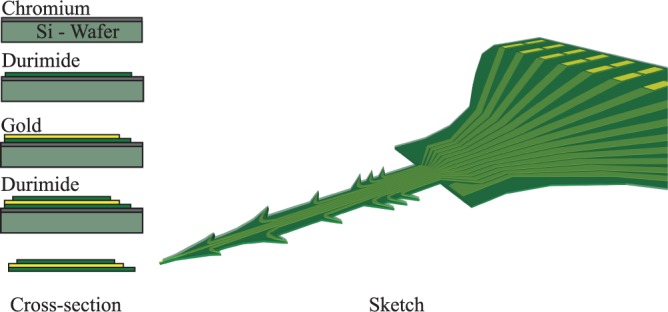
Schematic sketch of the different fabrication steps and an illustration of a finished array.
The final thickness was measured, using a profilometer just before the removal
of the sacrificial layer, to  m. Whereas the first Durimide layer
had a thickness of 2-
m. Whereas the first Durimide layer
had a thickness of 2- m
and the second layer a thickness of 5-
m
and the second layer a thickness of 5- m, this was done in to simplify the patterning
of the conductive layer.
m, this was done in to simplify the patterning
of the conductive layer.
To release the array from the silicon wafer, the sacrificial layer was etched using chromium etchant (Chrome etch, MicroChem Corp, USA), after which the arrays were rinsed thoroughly in deionized water. The whole process has a possibility to produce up to 79 arrays on each wafer.
The end of the connecting cable was soldered (NC297 DX 52In/48Sn soldering paste, AIM Specialty Materials, USA) to a printed circuit board that corresponds to a 30-channel Hirose Electric B10 connector. We used a In/Sn paste to ensure a good adhesion between the gold on the array and the PCB.
B. Evaluation of the Use of Chromium as a Sacrificial Layer
In order to investigate the amount of chromium that is left on an array after removal of the sacrificial chromium layer, a scanning electron microscope (SEM, JEOL 6700F) with an energy-dispersive X-ray spectroscopy detector was used. Arrays were mounted on mounting pins and a layer of carbon, 20 nm, was deposited on the arrays, the carbon was needed to allow for the analysis. The XPS analysis automatically detected gold, titanium and silicon, but the amount of chromium was below the detection limit of the detector. The XPS spectra received from the analysis after compensating for the background is shown in Fig. 2.
FIGURE 3.
SEM image of the finalized array; each array is numbered, so that users can easily keep track of them within the batch.
FIGURE 2.
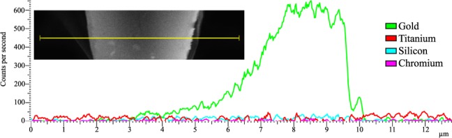
The XPS spectra received from the analysis together with a corresponding SEM from where the line scan was taken.
C. Evaluation of the Mechanical Stability
We tested the mechanical stability of the probe by bending unplatinized arrays around a 0.5 mm diameter wire. To visualize cracks in the insulation after the bending, we electroplated the electrode array and screened for platinization through the insulated part, using a light microscope and a SEM. Despite the substantial bending used, no visible cracks were found. The result is in line with the well documented flexibility of Durimide which has a Young's modulus of 2.5 GPa and can be elongated by 85% before it breaks [16], [21].
D. Platinization
To reduce the impedance
of the exposed electrode tip, which is largely dependent on its surface area,
a layer of platinum black was added by electroplating. The platinizing solution [14] consisted of 7 mM chloroplatinic acid
(8%, Sigma-Aldrich, Germany), 1 mM lead acetate (Sigma-Aldrich) and 0.03 mM
hydrochloric acid (37%, Merck, Germany) in aqueous solution. The electrode
was immersed into the platinizing solution using a platinum wire as the anode.
The electrodes were platinized using a potentiostat (Ivium CompactStat with
multiplexer; an Ag/Ag-Cl electrode was used as the reference) that applied
700 mV DC for 30 s. The combination of potentiostat and multiplexer allowed
the platinization of the recording sites one by one in a single session. The
maximum thickness observed, using SEM, of the platinization layer was roughly  m, together with the
thickness of the array the total thickness will be about
m, together with the
thickness of the array the total thickness will be about  m at the tips. Other
groups have developed flexible arrays with a similar thickness of 10-
m at the tips. Other
groups have developed flexible arrays with a similar thickness of 10- m [2], [8], [10], [22]–[24],
however, the size of the active sites on the
m [2], [8], [10], [22]–[24],
however, the size of the active sites on the  -foil is considerably smaller,
  m
m compared to
400-
compared to
400- m
m , in most prior
art.
, in most prior
art.
E. In Vitro Impedance Analysis
To evaluate the efficiency of the platinization process, electrode impedances were measured on gold electrodes and then on the same electrodes after the deposition of platinum black. The impedance (absolute value and phase) was measured over a frequency range of 100 Hz to 10 kHz in 0.9% saline solution using galvanostatic impedance analysis (Gamry Reference 600, with an Ag-AgCl reference electrode).
F. Implantation
Because
the manufactured electrode array was too flexible to be implanted without
support, a straight  m
tungsten wire (Advent Ltd, UK) was attached using caramelized sucrose (Merck,
Germany) as the adhesive. The tungsten wire was sharpened by etching in 50%
NaOH (Sigma-Aldrich, Germany) to ensure a good penetration of the brain.
m
tungsten wire (Advent Ltd, UK) was attached using caramelized sucrose (Merck,
Germany) as the adhesive. The tungsten wire was sharpened by etching in 50%
NaOH (Sigma-Aldrich, Germany) to ensure a good penetration of the brain.
Three male Sprague Dawley rats weighing 200–250 g were used for implantation. All animals received food and water ad libitum and were kept in a 12 h day/night cycle at a constant environmental temperature of 21°C (humidity, 65%). Approval for the experiments was obtained in advance from the Lund/Malmö local ethical committee on animal experiments, which is regulated by the code of regulations of the Swedish Board of Agriculture. These regulations, including directives from the European Union, follow the law on animal welfare legislated by the Swedish parliament. The County Administrative Board governs the implementation of the rules. Furthermore, the experiments were in accordance with policies and guidelines reported previously (Drummond 2009, Zimmerman 1983).
The animals were anesthetized with isoflurane (1.8–2.0%, during
surgery) in a mixture of 40% oxygen and 60% nitrous oxide. The trachea was
cannulated, the end-expiratory pCO (3.0–4.5%) was continuously monitored,
and the animal was mounted on a stereotactic frame. The rectal temperature
was kept between 36.5°C and 38.5°C using a feedback-regulated heating system.
A rostrocaudal incision was made in the skin along the central suture of the
skull, exposing the bregma. A craniotomy was made, and the dura mater was
split open to expose the primary sensory cortex (2 mm lateral and 1 mm caudal of bregma).
A platinum black modified
(3.0–4.5%) was continuously monitored,
and the animal was mounted on a stereotactic frame. The rectal temperature
was kept between 36.5°C and 38.5°C using a feedback-regulated heating system.
A rostrocaudal incision was made in the skin along the central suture of the
skull, exposing the bregma. A craniotomy was made, and the dura mater was
split open to expose the primary sensory cortex (2 mm lateral and 1 mm caudal of bregma).
A platinum black modified  -foil
electrode array was implanted at a speed of
-foil
electrode array was implanted at a speed of  m/s into the cortex to a depth of 1.8 mm using
a micromanipulator and was connected to a multichannel recording system (Plexon
Inc, USA). After rinsing the surface of the cortex with physiological saline
solution to dissolve the sucrose, the guide wire was removed.
m/s into the cortex to a depth of 1.8 mm using
a micromanipulator and was connected to a multichannel recording system (Plexon
Inc, USA). After rinsing the surface of the cortex with physiological saline
solution to dissolve the sucrose, the guide wire was removed.
G. Neural Recordings
After surgery,
anesthesia was lowered to 1% isoflurane (in the same gas mixture used above).
This level has previously been shown to yield reliable cortical potentials
after skin stimulation [25]. The
glabrous skin of the hind paw was stimulated intracutaneously with a train
of single electric pulses (1 mA,  s, 1 Hz) using fine steel needle electrodes [26]. The recorded signals were amplified
and filtered (amplification
s, 1 Hz) using fine steel needle electrodes [26]. The recorded signals were amplified
and filtered (amplification  ; for wideband/action potentials and calculations
of noise: sampling frequency 40 kHz, high-pass filter 0.5 Hz, low-pass filter
8 kHz; for evoked potentials: sampling frequency 1 kHz; high-pass filter 0.5
Hz, low-pass filter 400 Hz). After recordings, the animal was sacrificed using
a lethal dose of sodium pentobarbital (APL, Sweden).
; for wideband/action potentials and calculations
of noise: sampling frequency 40 kHz, high-pass filter 0.5 Hz, low-pass filter
8 kHz; for evoked potentials: sampling frequency 1 kHz; high-pass filter 0.5
Hz, low-pass filter 400 Hz). After recordings, the animal was sacrificed using
a lethal dose of sodium pentobarbital (APL, Sweden).
H. Noise Estimation
The root mean square (RMS) value of the signal (between spikes) is a good estimation of the noise. For signals without an offset component, the RMS value can be calculated as the standard deviation [27]. The wideband data were high-pass filtered (300 Hz) using Matlab (Mathworks, Sweden), followed by the calculation of the standard deviation using [28]–[30] (1):
 |
where  is the estimated
standard deviation of the noise and
is the estimated
standard deviation of the noise and  is
the filtered signal. The constant 0.6745 is needed to calibrate the estimator
for normal distributed white Gaussian noise. The signal-to-noise ratio (SNR)
was then calculated using (2),
is
the filtered signal. The constant 0.6745 is needed to calibrate the estimator
for normal distributed white Gaussian noise. The signal-to-noise ratio (SNR)
was then calculated using (2),
 |
where the spike detection was carried out by applying a nonlinear energy operator (NEO) to the signal and then setting the threshold to 20 times the mean of the NEO. The NEO is given by (3),
 |
where  is the
signal. The NEO provides an estimate of the local energy of the signal and
is commonly used to emphasize spikes in the presence of background noise [31].
is the
signal. The NEO provides an estimate of the local energy of the signal and
is commonly used to emphasize spikes in the presence of background noise [31].
III. Results
A. Design and Fabrication
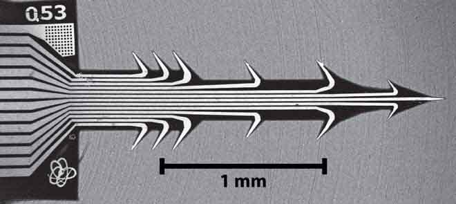
This study describes the development of an electrode array made of photostructurable polymer and comprising 13 recording electrodes and one reference electrode in each array. The photostructurability allows not only the manufacturing of arrays in batches, with good reproducibility, but also rapid changes in the design, thus providing the ability to adapt the design of the array depending on the architecture of the region of interest in the brain.
The electrode array (Fig. 2) developed here was tailored to the cortex cerebri and has the form of an arrow with a length of 1.8 mm with 13 extrusions, see Table 1 for a more details.
TABLE 1.

Design parameters of the array.
In the final design of the probe each protrusion contained a triangle shaped
recording site,  m
long and
m
long and  m
wide, with an area of approximately
m
wide, with an area of approximately  m
m . The recording sites were placed in the
tip of each protrusion in order to ensure a maximum exposure of the recording
site to the surrounding tissue.
. The recording sites were placed in the
tip of each protrusion in order to ensure a maximum exposure of the recording
site to the surrounding tissue.
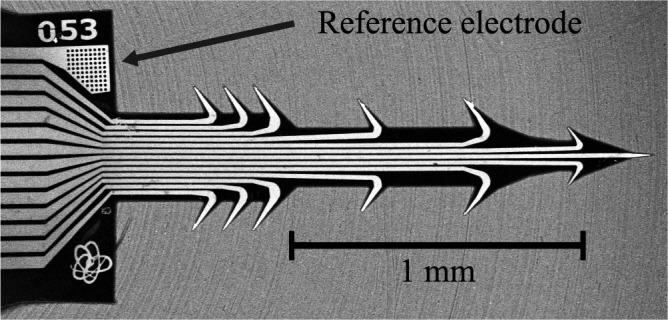
The reference gold electrode consists
of 75 holes (10  10
10  m) in the first layer
of Durimide in the probe, the reference electrode was placed on the opposite
side to the recording sites because we wanted to maximize the distance between
the reference and the recording sites.
m) in the first layer
of Durimide in the probe, the reference electrode was placed on the opposite
side to the recording sites because we wanted to maximize the distance between
the reference and the recording sites.
B. Platinization
The platinization protocol used was developed over two years, and the parameters were chosen based on how the resulting coating looked and acted. The two parameters that can be changed are the voltage and time: increasing the voltage will increase the speed of the build-up of the coating; increasing the speed will give rise to a coating that consists of many branches that are good at lowering the impedance but are fragile, whereas a low speed will yield a coating that resembles a sponge that is more durable but does not lower the impedance as much. The final protocol was a compromise between durability and the expansion of the surface area [32]; and the final parameters were a voltage of 0.7 V for 30 s, the result of which can be seen in Fig. 4.
FIGURE 4.
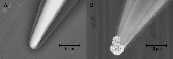
SEM images of tips before (A) and after (B) platinization. Note the considerable enlargement of the surface area of the tip shown in B.
C. In Vitro Impedance Analysis
The
results of the in vitro impedance analysis are shown in Fig. 5 and in Table
2. The impedance of the electrodes was lowered by up to almost two
decades after the modification with platinum black. The recorded values of
the impedance at a frequency of 1 kHz for gold electrodes had a mean value
(number of measurements  )
of 4.3 M
)
of 4.3 M compared
with 63 k
compared
with 63 k for
the same electrodes after modification using platinum black. The resulting
impedance for the gold electrodes was comparable to those available commercially
and those reported by other groups [2].
The big variance of the impedance is due to the fact that the size of the
recording sites are dependent on how well one has aligned the insulating Durimide
layer. A small misalignment of
for
the same electrodes after modification using platinum black. The resulting
impedance for the gold electrodes was comparable to those available commercially
and those reported by other groups [2].
The big variance of the impedance is due to the fact that the size of the
recording sites are dependent on how well one has aligned the insulating Durimide
layer. A small misalignment of  m will give a change in size of the recording
site of roughly 30–40 %.
m will give a change in size of the recording
site of roughly 30–40 %.
FIGURE 5.
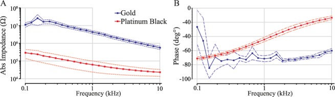
Results
of the in vitro impedance analysis. The absolute impedance
(A) and the phase shift (B) were plotted vs frequency. The solid line shows
the mean,  ,
and the dashed line shows the 95% confidence interval.
,
and the dashed line shows the 95% confidence interval.
TABLE 2.

Recorded values of impedance together with standard deviation
vs frequency for gold electrodes and the same electrodes after platinization,n
The phase analysis of the arrays (Fig. 4B) showed that the capacitive phase shift for a platinized electrode decreased with increasing frequency.
D. In Vivo Recordings
To evaluate the in vivo recording
properties of the platinized electrode array, acute recordings were performed
from the somatosensory cortex of three animals. From all the electrode sites,
including the reference electrode used as the surface electrode site, on the
array, clear evoked potentials (mean onset and peak latency, 12 ms and 22
ms, respectively) could be recorded after intracutaneous electrical stimulation
of the glabrous skin of the hind paw using fine steel needle electrodes [26]. The averaged cortical recordings
( )
from one rat are shown in Fig. 6. with
similar depth profile in all three animals. The recorded field potentials
that were evoked simultaneously in different layers of the cortex were consistent
with the depth profile of these potentials reported by earlier studies using
multiple measurements at different cortical depths with single-probe technique [33]. For instance, maximal negative field
potentials were obtained from the electrode sites at a depth of
)
from one rat are shown in Fig. 6. with
similar depth profile in all three animals. The recorded field potentials
that were evoked simultaneously in different layers of the cortex were consistent
with the depth profile of these potentials reported by earlier studies using
multiple measurements at different cortical depths with single-probe technique [33]. For instance, maximal negative field
potentials were obtained from the electrode sites at a depth of  m below the cortical
surface. This corresponds to layer IV of the cortex, which receives a direct
depolarizing thalamocortical input. These results prove that the recorded
neural signals were indeed picked up from the individual recording sites and
not significantly from the electrode shank. Fig.
7 shows three unfiltered raw data sweeps from different depths (
m below the cortical
surface. This corresponds to layer IV of the cortex, which receives a direct
depolarizing thalamocortical input. These results prove that the recorded
neural signals were indeed picked up from the individual recording sites and
not significantly from the electrode shank. Fig.
7 shows three unfiltered raw data sweeps from different depths ( m,
m,  m and
m and  m). Spikes can clearly
be seen on two channels, with no cross-talk to the middle channel. Furthermore,
the between electrode impedance was measured in air, resulting in identical
impedance data as for leaving the connector in air. For the recording site
placed at a depth of
m). Spikes can clearly
be seen on two channels, with no cross-talk to the middle channel. Furthermore,
the between electrode impedance was measured in air, resulting in identical
impedance data as for leaving the connector in air. For the recording site
placed at a depth of  m,
the noise of a single raw data sweep was calculated to
m,
the noise of a single raw data sweep was calculated to  V (RMS), and the SNR
was 19.2 dB.
V (RMS), and the SNR
was 19.2 dB.
FIGURE 6.
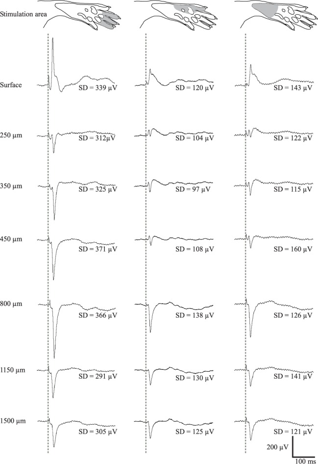
Depth profile of averaged ( ) evoked cortical potentials
from one rat together with the standard deviation. Electrical stimulation
(1 mA, 0.5 ms) of digits 2–4 (A) and lateral edge (B) and proximal part (C)
of the hind paw skin. The dashed line indicates time of electrical stimulation.
Note that since a normal depth profile was picked up by the u-foil array electrodes,
cross-talk between channels must be negligible. Since the signal is superimposed
on EEG the SD becomes relatively large.
) evoked cortical potentials
from one rat together with the standard deviation. Electrical stimulation
(1 mA, 0.5 ms) of digits 2–4 (A) and lateral edge (B) and proximal part (C)
of the hind paw skin. The dashed line indicates time of electrical stimulation.
Note that since a normal depth profile was picked up by the u-foil array electrodes,
cross-talk between channels must be negligible. Since the signal is superimposed
on EEG the SD becomes relatively large.
FIGURE 7.

Three
unfiltered raw data sweeps from three adjacent depths. Note the lack of cross-talk
between neural spikes in different channels. For the recording site at a depth
of  m,
the noise was
m,
the noise was  V
(RMS), and the SNR was 19.2 dB.
V
(RMS), and the SNR was 19.2 dB.
IV. Discussion
The electrode array
presented here, termed  -foil,
was designed to meet the need for a multichannel electrode array comprising
ultrathin and flexible electrodes with fixed interelectrode distances corresponding
to the distances between cortical laminae. Thus, the presented
design has the potential to enable neurophysiological studies that require
simultaneous recordings from neurons in different laminae in
a given cortical column, as demonstrated by the recordings obtained. It should
be noted that other types of multichannel electrode arrays, such as the Michigan
probe or derivates of this type, also allow recordings from neurons in different laminae
[34]. It should also be noted that there
has been work conducted in placing the active sites of the probe away from
the main body: Seymour et al
[35] developed
a probe with a main body and a lattice-like structure next to it, with histology
showing less encapsulation around the lattice than around the main body; Egert et
al
[36] developed a Michigan
like probe with the active sites placed on spring-like structures that could
be released into the tissue after implantation. The distinguishing features
of the probe presented here lie in its high flexibility and that the active
recording elements are placed on the distal part of protrusions from the shank
of the probe. It is well known that implanted probes are usually encapsulated
by a glial scar that may insulate and displace neurons away from the probe [6], [37].
Our hypothesis is that the protrusions should work in the same way as the
lattice in Seymour et al's
[35] work,
resulting in reduced encapsulation around the tips of the protrusion. This
hypothesis needs, however, to be evaluated in long-term studies. In addition,
the barb like protrusions could serve as local anchors that stabilize the
positions of the electrode tips in the tissue, therefore reducing variations
in recorded neural spike amplitudes.
-foil,
was designed to meet the need for a multichannel electrode array comprising
ultrathin and flexible electrodes with fixed interelectrode distances corresponding
to the distances between cortical laminae. Thus, the presented
design has the potential to enable neurophysiological studies that require
simultaneous recordings from neurons in different laminae in
a given cortical column, as demonstrated by the recordings obtained. It should
be noted that other types of multichannel electrode arrays, such as the Michigan
probe or derivates of this type, also allow recordings from neurons in different laminae
[34]. It should also be noted that there
has been work conducted in placing the active sites of the probe away from
the main body: Seymour et al
[35] developed
a probe with a main body and a lattice-like structure next to it, with histology
showing less encapsulation around the lattice than around the main body; Egert et
al
[36] developed a Michigan
like probe with the active sites placed on spring-like structures that could
be released into the tissue after implantation. The distinguishing features
of the probe presented here lie in its high flexibility and that the active
recording elements are placed on the distal part of protrusions from the shank
of the probe. It is well known that implanted probes are usually encapsulated
by a glial scar that may insulate and displace neurons away from the probe [6], [37].
Our hypothesis is that the protrusions should work in the same way as the
lattice in Seymour et al's
[35] work,
resulting in reduced encapsulation around the tips of the protrusion. This
hypothesis needs, however, to be evaluated in long-term studies. In addition,
the barb like protrusions could serve as local anchors that stabilize the
positions of the electrode tips in the tissue, therefore reducing variations
in recorded neural spike amplitudes.
In the present work, the bulk material was changed to Durimide, to provide a less fragile, yet flexible, construction compared with the original SU-8-based version [11], [12]. This resulted in a higher yield of functional electrodes in each array and in a more robust construction that reduced the risk of breakage of the electrodes during handling and during implantation. In addition, the recording data obtained demonstrated that adjacent electrode sites were capable of picking up independent neural electrical activity with essentially no cross-talk, indicating that the insulation properties of Durimide are adequate. Durimide is assumed to be biocompatible and is currently used as the bulk material in many biosensors [13], [17]–[20]. As Durimide is a photostructurable polymer, it is easy to modify the design of the array, such as the interelectrode distance, the length and angle of the protrusions, and the number of electrode sites on the array, to fit different types of tissue architecture.
In addition, the surface area of the uninsulated parts of the electrodes was significantly increased by electroplating the active sites with platinum black. This, in essence, transformed the electrode tips from a 2D surface to a spongy 3D volume with a much larger surface and, thus, less impedance. The idea behind using a 3D structure for the active site was to enhance the surface of the electrode tip that is in contact with neurons confined to a very small volume of brain tissue, hence reducing the short circuiting of the signals from nearby neurons. This aspect is likely to be especially critical in cases in which recordings from small neurons are attempted. In fact, the electrode impedance observed after coating with platinum black, using the chosen parameters, dropped by up to two decades in magnitude, resulting in a significantly lower noise level. This should also increase the signal-to-noise level of recorded spikes. The high signal-to-noise of some of the unit recordings obtained in the present study were in line with this assumption. Another observed effect of the platinization was that the variance in impedance between different electrode tips in the same array was reduced significantly (Table 1). The combined effect of lowering the impedance together with a smaller variance for the electrodes with platinum black is that the array is better compatible to the input impedance of the amplifier, resulting in a better signal fidelity. We believe that this difference is because the resulting platinum black area depends mostly on the electroplating conditions, which can be controlled precisely, whereas even a small variation in the fabrication alignment yields a large difference in the resulting electrode impedance for 2D surfaces. Although a lowered impedance and reduced variance in impedance can also be obtained by simply enlarging a 2D surface [38] this has the drawback of also increasing the short circuiting of signals from nearby neurons, thus lowering the amplitude of such neural spikes.
An important finding of this study was that after electroplating platinum black onto the gold tips, the impedance dropped significantly for higher frequencies (Fig. 5). This implies that the capacitance increases with increasing frequency and that the impedance for high frequencies is more dependent on the resistance. Hence, the recorded neural signals will be less distorted.
This study focus on the technical aspects of a new
design for a neural interface aiming at improving long term communication
with neurons and demonstrates that the  -foil electrode is a viable electrode design
for further in depth neurophysiology studies on biocompatibility and in vivo
performance. For instance, it will be necessary to evaluate the hypothesis
that there is less encapsulation around the tips of the protrusions as compared
to at the base of the electrode and evaluation of the stability achieved by
the barb like protrusions
-foil electrode is a viable electrode design
for further in depth neurophysiology studies on biocompatibility and in vivo
performance. For instance, it will be necessary to evaluate the hypothesis
that there is less encapsulation around the tips of the protrusions as compared
to at the base of the electrode and evaluation of the stability achieved by
the barb like protrusions
V. Conclusion
In
conclusion, we have developed a multichannel electrode array, termed  -foil, that comprises
ultrathin and flexible electrodes protruding from a thin polymer foil at fixed
distances. The interface impedance was reduced by up to two decades by electroplating
the electrode tips with platinum black. This also reduced the phase lag for
higher-frequency components. In vivo acute measurements from
rat cortex cerebri confirmed a high SNR for neural recordings,
and the absence of significant cross-talk between recording channels.
-foil, that comprises
ultrathin and flexible electrodes protruding from a thin polymer foil at fixed
distances. The interface impedance was reduced by up to two decades by electroplating
the electrode tips with platinum black. This also reduced the phase lag for
higher-frequency components. In vivo acute measurements from
rat cortex cerebri confirmed a high SNR for neural recordings,
and the absence of significant cross-talk between recording channels.
Acknowledgement
We would like to thank Palmi Thor Thorbergsson for all help with the SNR analysis.
Conflict of Interest
J. Schouenborg is stockholder of Neuronano Inc., who owns the intellectual property rights in the disclosed neural interface.
Funding Statement
This work was supported in part by the Swedish Research Council under Project 80337401 and Project 60012701, and the Knut and Alice Wallenberg Foundation under Project KAW 2004.0119.
References
- [1].Wise K. D. and Najafi K., “Microfabrication techniques for integrated sensors and microsystems,” Science, vol. 254, no. , pp. 1335–1342, 1991. [DOI] [PubMed] [Google Scholar]
- [2].McCarthy P. T., Rao M. P., and Otto K. J., “Simultaneous recording of rat auditory cortex and thalamus via a titanium-based, microfabricated, microelectrode device,” J. Neural Eng., vol. 8, no. 4, p. 046007, Aug. 2011. [DOI] [PMC free article] [PubMed] [Google Scholar]
- [3].Jones K. E., Campbell P. K., and Normann R. A., “A glass/silicon composite intracortical electrode array,” Ann. Biomed. Eng., vol. 20, no. 4, pp. 423–437, Jan. 1992. [DOI] [PubMed] [Google Scholar]
- [4].Maynard E. M., Nordhausen C. T., and Normann R. A., “The Utah intracortical electrode array: A recording structure for potential brain-computer interfaces,” Electroencephalogr. Clin. Neurophysiol., vol. 102, no. 3, pp. 228–239, Mar. 1997. [DOI] [PubMed] [Google Scholar]
- [5].Williams J. C., Rennaker R. L., and Kipke D. R., “Long-term neural recording characteristics of wire microelectrode arrays implanted in cerebral cortex,” Brain Res. Protocols, vol. 4, no. 3, pp. 303–313, Dec. 1999. [DOI] [PubMed] [Google Scholar]
- [6].Thelin J., et al. , “Implant size and fixation mode strongly influence tissue reactions in the CNS,” PLOS One, vol. 6, no. 1, p. e16267, Jan. 2011. [DOI] [PMC free article] [PubMed] [Google Scholar]
- [7].Rousche P. J., Pellinen D. S., Pivin D. P. Jr., Williams J. C., Vetter R. J., and Kipke D. R., “Flexible polyimide-based intracortical electrode arrays with bioactive capability,” IEEE Trans. Biomed. Eng., vol. 48, no. 3, pp. 361–371, Mar. 2001. [DOI] [PubMed] [Google Scholar]
- [8].Lee K.-K., et al. , “Polyimide-based intracortical neural implant with improved structural stiffness,” J. Micromech. Microeng., vol. 14, no. 1, pp. 32–37, Jan. 2004. [Google Scholar]
- [9].Stieglitz T., et al. , “Brain-computer interfaces: An overview of the hardware to record neural signals from the cortex,” Prog. Brain Res., vol. 175, pp. 297–315, 2009, doi:10.1016/S0079-6123(09)17521-0. [DOI] [PubMed] [Google Scholar]
- [10].Mercanzini A., et al. , “Demonstration of cortical recording using novel flexible polymer neural probes,” Sensors Actuat. A, Phys., vol. 143, no. 1, pp. 90–96, May 2008. [Google Scholar]
- [11].Kohler P., et al. , “Flexible multi electrode brain-machine interface for recording in the cerebellum,” in Proc. IEEE Annu. Int. Conf. Eng. Med. Biol. Soc., Sep. 2009, pp. 536–538. [DOI] [PubMed] [Google Scholar]
- [12].Ejserholm F., Köhler P., Bengtsson M., Jörntell H., Schouenborg J., and Wallman L., “A polymer based electrode array for recordings in the cerebellum,” in Proc. 5th Int. IEEE/EMBS Conf. Neural Eng., Apr-May 2011, pp. 376–379. [Google Scholar]
- [13].Rubehn B. and Stieglitz T., “In vitro evaluation of the long-term stability of polyimide as a material for neural implants,” Biomaterials, vol. 31, no. 13, pp. 3449–3458, May 2010. [DOI] [PubMed] [Google Scholar]
- [14].Feng R. and Farris R. J., “Influence of processing conditions on the thermal and mechanical properties of SU8 negative photoresist coatings,” J. Micromech. Microeng., vol. 13, no. 1, pp. 80–88, Jan. 2003. [Google Scholar]
- [15].Wouters K. and Puers R., “Determining the Young's modulus and creep effects in three different photo definable epoxies for MEMS applications,” Sensors Actuat. A, Phys., vol. 156, no. 1, pp. 196–200, Nov. 2009. [Google Scholar]
- [16].Stieglitz T., Schuettler M., Rubehn B., Boretius T., Badia J., and Navarro X., “Evaluation of polyimide as substrate material for electrodes to interface the peripheral nervous system,” in Proc. 5th Int. IEEE/EMBS Conf. Neural Eng., Apr-May 2011, pp. 529–533. [Google Scholar]
- [17].Seo J.-M., Kim S. J., Chung H., Kim E. T., Yu H. G., and Yu Y. S., “Biocompatibility of polyimide microelectrode array for retinal stimulation,” Mater. Sci. Eng., C, vol. 24, nos. 1–2, pp. 185–189, Jan. 2004. [Google Scholar]
- [18].Richardson R. R. Jr., Miller J. A., and Reichert W. M., “Polyimides as biomaterials: Preliminary biocompatibility testing,” Biomaterials, vol. 14, no. 8, pp. 627–635, Jul. 1993. [DOI] [PubMed] [Google Scholar]
- [19].Ceballos D., Valero A., Valderrama E., Stieglitz T., and Navarro X., “Polyimide cuff electrodes for peripheral nerve stimulation,” J. Neurosci. Methods, vol. 98, no. 2, pp. 105–118, 2000. [DOI] [PubMed] [Google Scholar]
- [20].Sun Y., Lacour S. P., Brooks R. A., Rushton N., Fawcett J., and Cameron R. E., “Assessment of the biocompatibility of photosensitive polyimide for implantable medical device use,” J. Biomed. Mater. Res., A, vol. 90, no. 3, pp. 648–655, Sep. 2009. [DOI] [PubMed] [Google Scholar]
- [21].Töpper M., Fischer T., Baumgartner T., and Reichl H., “A comparison of thin film polymers for Wafer Level Packaging,” in Proc. 60th ECTC, Jun. 2010, pp. 769–776. [Google Scholar]
- [22].Lago N., Yoshida K., Koch K. P., and Navarro X., “Assessment of biocompatibility of chronically implanted polyimide and platinum intrafascicular electrodes,” IEEE Trans. Biomed. Eng., vol. 54, no. 2, pp. 281–290, Feb. 2007. [DOI] [PubMed] [Google Scholar]
- [23].Kato Y. X., Furukawa S., Samejima K., Hironaka N., and Kashino M., “Photosensitive-polyimide based method for fabricating various neural electrode architectures,” Frontiers Neuroeng., vol. 5, p. 11, Jun. 2012. [DOI] [PMC free article] [PubMed] [Google Scholar]
- [24].Cheung K. C., Renaud P., Tanila H., and Djupsund K., “Flexible polyimide microelectrode array for in vivo recordings and current source density analysis,” Biosensors Bioelectron., vol. 22, no. 8, pp. 1783–1790, Mar. 2007. [DOI] [PubMed] [Google Scholar]
- [25].Granmo M., Jensen T., and Schouenborg J., “Nociceptive transmission to rat primary somatosensory cortex-comparison of sedative and analgesic effects,” PLOS One, vol. 8, no. 1, p. e53966, Jan. 2013. [DOI] [PMC free article] [PubMed] [Google Scholar]
- [26].Petersson P., Granmo M., and Schouenborg J., “Properties of an adult spinal sensorimotor circuit shaped through early postnatal experience,” J. Neurophysiol., vol. 92, no. 1, pp. 280–288, Jul. 2004. [DOI] [PubMed] [Google Scholar]
- [27].Bissell C. C. and Chapman D. A., “Random signals and noise,” in Digital Signal Transmission, 2nd ed. Cambridge, U.K.: Cambridge Univ. Press, 1992, p. 64. [Google Scholar]
- [28].Donoho D. L. and Johnstone J. M., “Ideal spatial adaptation by wavelet shrinkage,” Biometrika, vol. 81, no. 3, pp. 425–455, 1994. [Google Scholar]
- [29].Quiroga R. Q., Nadasdy Z., and Ben-Shaul Y., “Unsupervised spike detection and sorting with wavelets and superparamagnetic clustering,” Neural Comput., vol. 16, no. 8, pp. 1661–1687, Aug. 2004. [DOI] [PubMed] [Google Scholar]
- [30].Chouakri S. A., Bereksi-Reguig F., Ahmaïdi S., and Fokapu O., “Wavelet denoising of the electrocardiogram signal based on the corrupted noise estimation,” in Proc. Comput. Cardiol., vol. 32 Sep. 2005, pp. 1021–1024. [Google Scholar]
- [31].Obeid I. and Wolf P. D., “Evaluation of spike-detection algorithms for a brain-machine interface application,” IEEE Trans. Biomed. Eng., vol. 51, no. 6, pp. 905–911, Jun. 2004. [DOI] [PubMed] [Google Scholar]
- [32].Merrill E. G. and Ainsworth A., “Glass-coated platinum-plated tungsten microelectrodes,” Med. Biol. Eng., vol. 10, no. 5, pp. 662–672, Sep. 1972. [DOI] [PubMed] [Google Scholar]
- [33].Kalliomäki J., Weng H.-R., Nilsson H.-J., and Schouenborg J., “Nociceptive C fibre input to the primary somatosensory cortex (SI). A field potential study in the rat,” Brain Res., vol. 622, nos. 1–2, pp. 262–270, Sep. 1993. [DOI] [PubMed] [Google Scholar]
- [34].Yang J.-W., Shih H.-C., and Shyu B.-C., “Intracortical circuits in rat anterior cingulate cortex are activated by nociceptive inputs mediated by medial thalamus,” J. Neurophysiol., vol. 96, no. 6, pp. 3409–3422, Dec. 2006. [DOI] [PubMed] [Google Scholar]
- [35].Seymour J. P. and Kipke D. R., “Neural probe design for reduced tissue encapsulation in CNS,” Biomaterials, vol. 28, no. 25, pp. 3594–3607, Sep. 2007. [DOI] [PubMed] [Google Scholar]
- [36].Egert D. and Najafi K., “New class of chronic recording multichannel neural probes with post-implant self-deployed satellite recording sites,” in Proc. 16th TRANSDUCERS, Jun. 2011, pp. 958–961. [Google Scholar]
- [37].Skousen J. L., Merriam S. M. E., Srivannavit O., Perlin G., Wise K. D., and Tresco P. A., Reducing Surface Area While Maintaining Implant Penetrating Profile Lowers the Brain Foreign Body Response to Chronically Implanted Planar Silicon Microelectrode Arrays, vol. 194, 1st ed. New York, NY, USA: Elsevier, 2011, pp. 167–180. [DOI] [PubMed] [Google Scholar]
- [38].Abdurrahman A. R., Price D. T., and Bhansali S., “Effect of electrode geometry on the impedance evaluation of tissue and cell culture,” Sensors Actuat. B, Chem., vol. 127, no. 1, pp. 89–96, Oct. 2007. [Google Scholar]