Abstract
Miniaturized helix antennas are integrated with drug reservoirs to function as RFID wireless tag sensors for real-time drug dosage monitoring. The general design procedure of this type of biomedical antenna sensors is proposed based on electromagnetic theory and finite element simulation. A cost effective fabrication process is utilized to encapsulate the antenna sensor within a biocompatible package layer using PDMS material, and at the same time form a drug storage or drug delivery unit inside the sensor. The in vitro experiment on two prototypes of antenna sensor-drug reservoir assembly have shown the ability to monitor the drug dosage by tracking antenna resonant frequency shift from 2.4–2.5-GHz ISM band with realized sensitivity of 1.27  for transdermal drug delivery monitoring and 2.76-
 sensitivity for implanted drug delivery monitoring.
Keywords: Drug delivery system, medical implants, wireless sensor, electrically small antenna, helix antenna, RFID
I. Introduction
DRIVEN by the rise of micro and nano technologies, controlled rate and micro-patterned drug deliveries have been playing major roles to overcome the limitations of conventional burst-release dosage forms [1]. Instead of injecting drugs at the maximum tolerable dose (MTD) once in a treatment period, contemporary drug delivery paradigms maintain the constant release and administer it within some desired therapeutic range, providing minimized side effects and increased therapeutic efficacy [2], [3]. Drug delivery systems may have different control mechanisms [2]–[7], but no matter what control mechanism is adopted, drug dosage monitoring is crucial to provide feedback as well as prevent unexpected in-vivo fluctuation and leakage. In addition, dosage monitoring will also benefit the RFID (Radio Frequency Identification) platform enabled personalized medical tracking and chronic disease management.
During the past decade, various drug delivery monitoring technologies have been developed such as photoacoustic tomography [8], electron paramagnetic resonance [9], and fluorescence based imaging [10]. Even though the size and cost of drug delivery system are continuously going down, most of the existing monitoring methods still involve bulky equipments and expensive test process. In this paper we propose a cost effective wireless drug dosage monitoring approach utilizing an RFID tag helix antenna sensor encapsulated within biocompatible package as a fully-assembled drug storage and delivery unit.
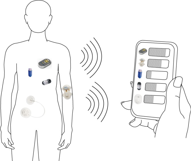
The concept of the wireless drug dosage monitoring system is shown in Fig. 1. With properly designed and customized antenna sensors, the drug volume inside transdermal drug delivery devices (for example, MiniMed™ insulin pump [11], Empi Action Patch™[12]) or implanted drug delivery devices (for example, SmartPill™[13], Philips iPill™[14] and MicroCHIPS™ [15]), can be tracked in real-time. The external control and monitoring unit can be any RFID reader embedded portable device, like tablet and smart phone. This would be a major attractive feature of the sensor as it potentially makes up some important part of the nodes in a wireless health network [16].
Fig. 1. Illustration of the proposed real time drug delivery monitoring system. Utilizing the antenna drug dosage sensors, a smart phone can track the drug volume in multiple drug delivery devices.
The remainder of this paper is organized as follows: In Section II, the electromagnetic theory is developed to explain the antenna sensing mechanism. The simulation procedure and design consideration of the sensor is carried out in Section III. Section IV is dedicated to fabrication process of the antenna sensor-biocompatible packaging assembly. Section V contains the in-vitro test setup and experimental results for the finalized design. Section VI proposes a tag circuit block diagram for the antenna sensor. Section VII concludes this work.
II. Electromagnetic Theory of Dielectric Loaded Helix Antenna Sensor
A helix antenna wrapped around a core of dielectric material is called a dielectric-loaded helix antenna [17]. Different core materials with different effective permittivities will affect the radiation properties of the antenna. For liquids like water, body fluids and liquid drugs, the relative permittivity is high, usually at 60–80 range at RF and microwave frequencies [18]; by contrast, solid-state organic powders have much lower relative permittivity at the range of 1–5. With the same helix antenna, when the core are loaded with liquids, the resonant frequency of the antenna is lower than when air or powders are filled in. As shown in Fig. 1, for transdermal drug deliveries [5], since the drugs are in liquid state (large permittivity  ), the antenna resonant frequency will shift up as the drug releases. For implanted drug deliveries [2], [3], the initial state is full of powders (small
  ). As the drug releases, body fluids (large
  ) will fill in, and the resonant frequency will shift down.
During drug delivery process, whether it is liquid-air exchange or powder-liquid exchange, there is a large contrast of permittivity between the exchanging materials. The dielectric-loaded antenna itself can be considered as a cavity resonator. For an ideal helix antenna with a large number of turns, when the interface between the high  material (liquid) and the low
  material (air or powder) shifts, its resonant frequency change can be analyzed by perturbation theory [17].
Suppose a small shape perturbation  is applied to a dielectric resonator
  resonating at
  , the resulting resonant frequency
  will satisfy [19]:
 |
where  and
and  are the relative permittivity and permeability of the liquid material loaded inside the helix antenna. In addition, the electromagnetic field inside a helix coil is intense and almost constant along the cylinder direction
  , namely
 |
Then when liquid level shifts from  to
to  , we have
 |
Equation (3) is valid for electrically small helix antennas with large number of helix turns, inside which the inner field distribution is almost uniform [20]. From (3), we know that the resonant frequency shift will be linearly dependent on the liquid surface level shift. In practice, however, the core inside the dielectric-loaded helix is not a perfect cavity resonator, and when the number of turn is not very large the electric field along the cylinder won't be uniform. Therefore, perturbation theory can only conceptually predict the variation of resonant frequency with respect to the filling ratio of dielectric core. Accurate and reliable antenna sensor design needs to be evaluated by full-wave electromagnetic simulation and experimental validation.
III. Antenna Sensor Design Through FEM Simulation
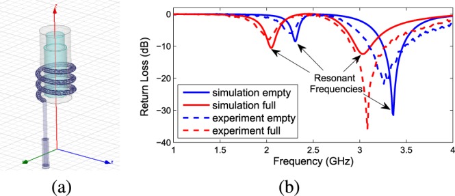
The radiation properties of the tag helix antenna sensor are simulated using Ansoft High Frequency Simulation Structure (HFSS), an electromagnetic simulation software based on the finite element method (FEM) [21]. In the model for our initial design, as shown in Fig. 2(a), the helix antenna is simply wrapped around a teflon cylinder  reservoir without any packaging layer (which will be discussed in Section IV). The reservoir is filled in with liquid similar to water (
 at room temperature, accurate enough for low concentration drug solutions), and the antenna resonant frequencies will shift when the liquid dosage changes, as shown in Fig. 2(b).
Fig. 2. A simulation-experiment comparison to validate the initial setup: (a). The antenna sensor in the HFSS simulation interface; (b). The simulated and measured return loss of the antenna sensor at full state (loaded with liquid drugs) against empty state.
A cylindrical helix antenna is defined by its radius, number of turns and pitch gap (or pitch angle) between adjacent turns. Normally the radius variation can be easily represented by scaling, so the impact of three other helix parameters on antenna sensor performance is investigated here through HFSS simulation. The results are in terms of sensitivity curves showing the resonant frequencies under 0%–100% normalized drug dosage levels which is included in Fig. 3. Fig. 3(a) shows the sensitivity curves of an antenna sensor with 2.5mm mm pitch gap and varying number of turns. As the number of turns increases, the whole curve moves downward to lower frequencies. Whereas in Fig. 3(b), the whole curve moves upward to higher frequencies as the pitch gap increases. Such result can be explained by modeling the helix as a solenoid coil. Hence the performance of the antenna sensor can be properly adjusted by changing its number of turns and pitch gap.
Fig. 3. Simulation of the sensitivity curves of the helix antenna sensor with different design parameters: (a). Tuning number of turns. (b). Tuning pitch gap. (c). Tuning the helix position along the reservoir. (d). The influence of antenna sensor orientation.
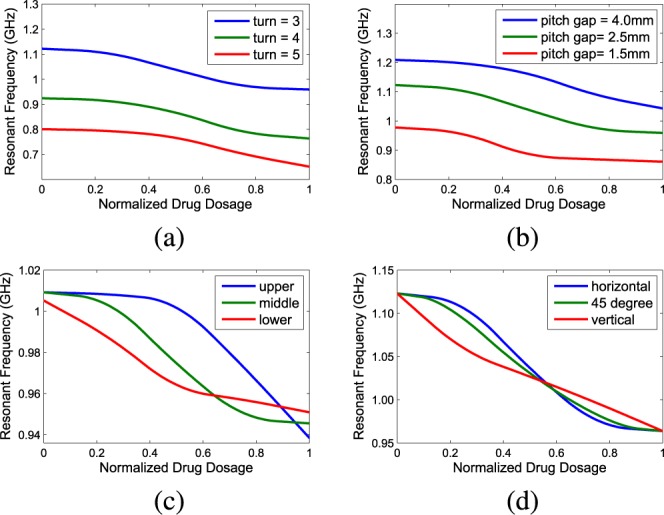
It is important to point out that when the number of turns or the pitch gap is large enough to make the helix antenna cover the whole cylinder body, the sensor is mostly linear in the middle range, but globally it is not linear, due to the reason that has been discussed in Section II. When the helix antenna is not long enough to cover the cylinder completely, the relative position of the antenna is critical to optimize the sensor performance. Fig. 3(c) shows the simulation result of an antenna that only covers half of the cylinder, and is placed at three different spots alongside the cylinder. It can be seen that the antenna sensor is much less sensitive when the liquid-air interface is out of the helix coil covered region.
Another interesting fact is that, under certain scenarios, the drug container may be placed at different angles, and the impact of the helix orientation must be identified. The sensitivity curves of a long helix antenna covering the whole cylinder placed at different orientations is shown in Fig. 3(d). In this simulation, the liquid-air interface is set to be horizontal, vertical and 45 degree against the ground. The differences among the curves indicate that the antennas are vulnerable to rotation, with an error up to 25%. So it is important to also take the placement angle of antenna into consideration.
The general design goal is to maximize the sensitivity and linearity across the band of interest, therefore the challenge is to ensure the antenna resonant frequency shifts within certain range when the drug dosage varies from 0%–100% of the volume of the drug reservoir. Drug reservoirs with different sizes and geometries require customized antenna sensors for optimized drug dosage monitoring performance, so there is no universal design. However, through parameter tuning as shown in Fig. 3 plus some scaling method (for example, scale the antenna sensor by a factor of 0.5 will double the resonant frequencies from around 1 GHz to around 2 GHz) can quickly achieve desired sensor performances. In our initial design, the antenna has 4.5mm mm radius and 3 helix turns with 2.5mm mm pitch gap between the adjacent turns, as shown in Fig. 2(a). Such initial design is validated by experimental tests, for which the detailed measurement procedure will be included in Section V. Comparison between the simulation of the antenna return loss  and the tested return loss is shown in Fig. 2(b). Two resonances can be observed, one is around 2.35 GHz, the other is around 3.4 GHz when the reservoir is empty. After the cylinder is filled in with liquid, the two resonant frequencies shift to 2.0 GHz and 3.0 GHz, respectively. It can be seen that for the initial model, the simulation result matches the measurement result well at both resonant frequencies, showing similar patterns of
  profile and resonance shift after the material changes inside the reservoir. However, in practice, when the metal wire is buried inside the package layer, the HFSS simulation can no longer predict the actual sensor performance very accurately and there requires some empirical tuning. When the antenna size is downsized to electrically small region, the radiation efficiency and directivity are typically low. The simulated radiation efficiency for the initial design is 58.7% and directivity is 1.838 dBi at resonance. This work does not focus on electrically small antenna optimization, rather we aim to design the antenna as a good sensor with acceptable antenna performance, as there are tradeoffs between the two design directions.
IV. Low Cost Fabrication of Antenna Sensors
A. Antenna Fabrication
The miniaturized 3-dimensional antennas can be fabricated using different techniques, for example, laser printing [22] and molding process [23]. In this work, we use molding process for the antenna sensor demonstration. First, a mold with the designed geometrical parameters is fabricated using the selective laser sintering (SLS) machine, then copper wire antennas can be duplicated out from the mold [23]. Due to the special structure of helix antenna, sometimes standard screws with proper parameters can be directly used as the mold to make the miniaturized helix antenna. Here we use wire antenna for demonstrative purpose, for printed antenna the cost of manufacturing can be even lower for mass production.
B. Package-Antenna Assembly
The antenna can be assembled on the package of a medical implant or a drug delivery unit [23]. The larger volume an electrically small antenna occupies, the higher bandwidth it will have in general. For any implanted electronic device, it is beneficial to have a three-dimensional antenna placed around the implant package in order to provide higher bandwidth for the antenna, in contrast of having a two dimensional planar antenna placed inside the package. Especially for implanted drug delivery devices, an antenna-package assembly design can also save a significant portion of the device volume for the drug reservoir and RFID drug delivery control unit, thus extending the effective time span of the drug delivery implant.
In this demonstration, we utilize a package-antenna assembly configuration in which the antenna and any tag ICs are embedded inside the package layer. For implanted drug delivery usually a biocompatible packaging material is required in order to prevent metal leaching into the body. In the antenna sensor demonstration, copper wire antenna and Polydimethylsiloxane (PDMS) package are used for the antenna-package assembly. PDMS is a Si based organic polymer widely used in micro fabrication and device encapsulation. Its bio-compatibility, high chemical inertness, as long as its mechanical property—flexible, but sturdy enough to tolerate bending across macroscopic scales, make it a very suitable and safe material [24]. Even for the transdermal drug delivery where the device is attached to the skin and there is less space restriction and less bio-safety consideration, the antenna-PDMS packaging assembly is still an advantageous solution.
C. PDMS Packaging Process
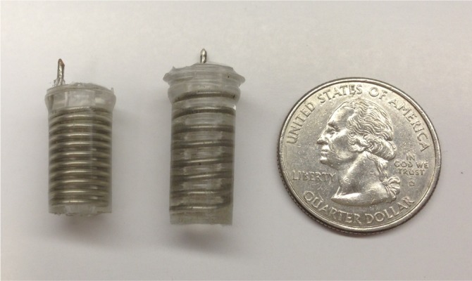
The fabrication process of the antenna-package assembly is shown in Fig. 4. First the helix antenna feed tip is fixed at the top of a reservoir mold in order to stabilize the antenna, allowing the helix wire winding around the cylinder part of the reservoir mold without touching the mold. As shown from Fig. 4(a) and (b), the reservoir mold along with the wire antenna is then placed into a package mold filled in with PDMS mixture liquids (ten parts PDMS base and one part curing agent). The whole set is then kept in a desiccator for one hour to eliminate all the trapped air bubbles, followed by 40 mins curing in a 125°C oven. After the PDMS is solidified and cross linked, the package mold can be released as shown in Fig. 4(c). The device was cooled down at  in the refrigerator, in order to take off the reservoir mold. When both molds have been taken off as shown in Fig. 4(d), the final step for the demonstrative device is to drill some holes at the bottom as outlets for the drugs, as shown in Fig. 4(e). Examples of two fabricated antenna sensors with different reservoir capacities and antenna parameters are shown in Fig. 5. The antenna sensor at the left has 4.9mm mm radius, 11 turns and 1.5mm mm pitch, with a 0.117 ml reservoir inside. The helix antenna sensor at the right has 4.8mm mm radius, 8 turns and 2.3mm mm pitch gap, with a 0.221 ml reservoir inside.
Fig. 4. The fabrication process of the antenna-package assembly.
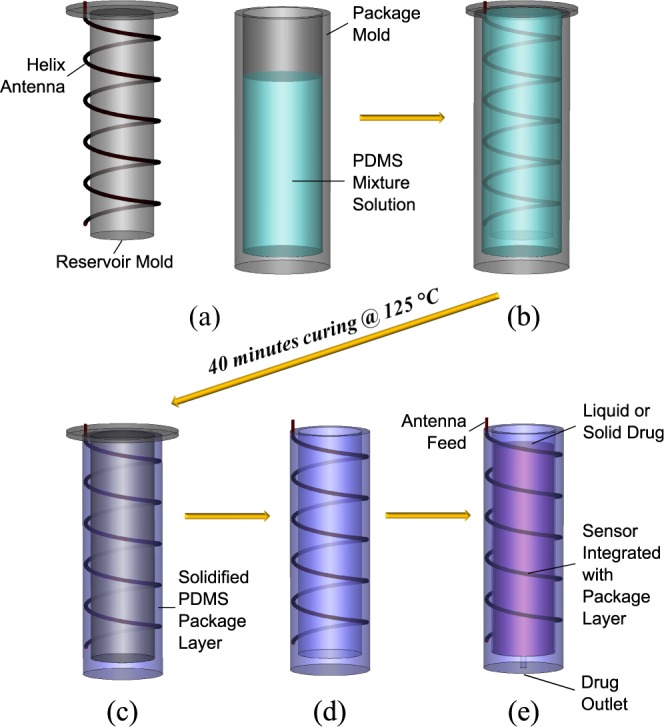
Fig. 5. The manufactured antenna sensors with PDMS packaging.
D. Discussion on the Package Thickness
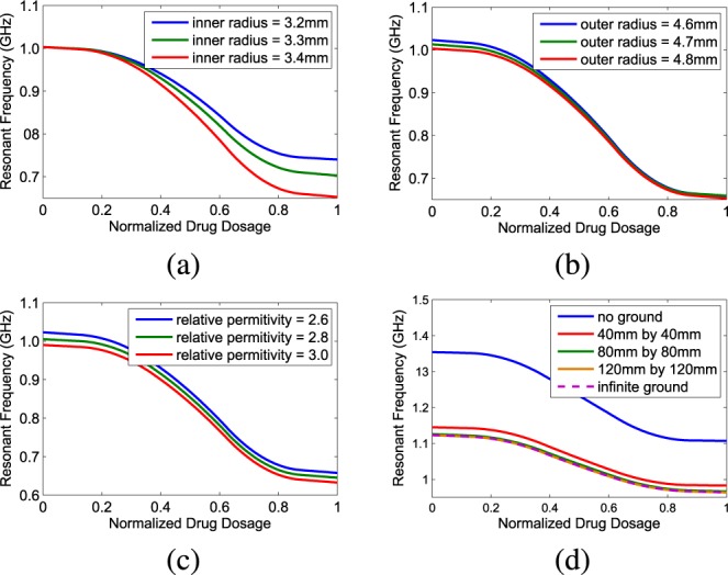
The PDMS package layer also has impact on the performance of the antenna sensor. Generally, thinner package layer is preferred in order to reduce the intrinsic loss of PDMS, though a very thin layer raises the risk of package breakage and exposing the antenna metal wire to the body. An optimized thickness takes both wireless transmission power efficiency and the bio-safety into account, and it is important to study the role of package layer thickness in the whole sensor design. HFSS simulation of an antenna sensor with the PDMS package layer is shown in Fig. 6. In Fig. 6(a), varying inner radius leads to different sensitivity curves when the outer radius is set to be 4.8mm. We can see that the inner radius makes a noticeable difference when liquid drug dosage is high; while from Fig. 6(b), it can be seen that the influence of package outer radius on the sensor is minimal. Fig. 6(c) shows the impact of the relative permittivity variation of PDMS material on sensitivity curves, which only moves the curve without effecting the local sensitivities. After the package impacts have also been taken into consideration as part of the sensor design parameter optimization, in our final devices, the copper wire is fixed at 1mm mm in diameter and the package layer thickness is chosen to be a variable from 1.5mm mm to 2.5mm mm thickness range.
Fig. 6. Simulation of the sensitivity curves of the helix antenna sensor-PDMS package assembly under variant conditions: (a). The influence of inner radius of the PDMS cylinder. (b). The influence of outer radius of the PDMS cylinder. (c). The influence of relative permittivity of the PDMS material. (d). The influence of metal ground plane size.
E. Discussion on the Ground Plane Size Effect
For the helix antenna, an infinite ground plane is usually assumed to be presented to make it a perfect monopole type antenna. In practice for drug delivery devices there is limited space to place the ground plane. In order to examine the impact of finite ground plane, a simulation study is shown in Fig. 6(d). We can see that without ground plane the whole sensitivity curve will move upward to higher frequencies. It can be also observed that when the ground plane is larger than 80mm mm by 80 mm, the sensitivity curve will be almost identical as the one with infinite ground plane. For real products, a small circular metal plane can be added at the bottom of the cylinder reservoir to adjust the antenna sensor performance. Our demonstrative devices do not contain ground plane to simplify the design and fabrication.
V. In-Vitro Experiments
A. Experimental Setup
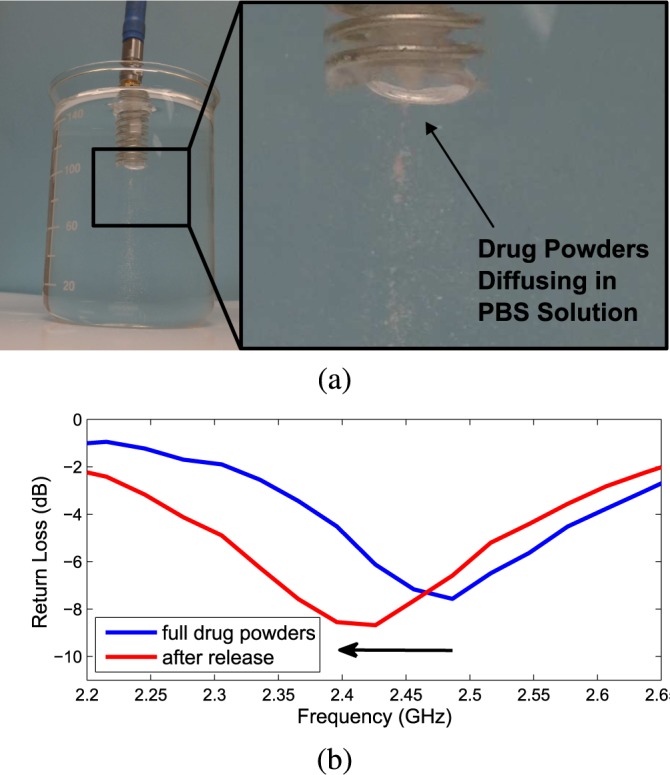
The in-vitro experiment to test the antenna sensor performance is carried out using an Agilent E8361C 10 MHz–67 GHz PNA network analyzer connected with a DC–40 GHz co-axial RF cable. The experimental setups are different for transdermal drug delivery and implanted drug delivery demonstrations. For transdermal drug delivery it is air surrounded environment. In the demonstration, the reservoir was initially empty and gradually filled in with liquid drugs (5% glucose solution, with estimated  very similar to water) from a syringe, as shown in Fig. 7(a). This is the reverse process of releasing the liquid drugs out of the reservoir, but because it is quasi-static process the test results will represent the actual drug dosage level. For implanted drug delivery it is body fluids surrounded environment. Instead of real serum or blood, we use phosphate buffered saline (PBS) solution (with estimated
  ) to mimic the body fluids. The device is tested inside PBS and the reservoir is initially filled with drug powders (resveratrol, with material
  while its powder state effective
  should be much lower). Through the outlets, drug powders will naturally diffuse into the PBS solution and at the same time the incoming PBS solution will gradually replace the volume inside the reservoir as shown in Fig. 8(a). In order to slow down and control the diffusion rate, a simple filter is placed at the outlet. This experiment only includes simple drug delivery control but the test for the real time monitoring ability of the helix antenna sensors are applicable for any advanced drug delivery system.
Fig. 7. In-vitro experiment on the dosage monitoring sensor for intradermal drug delivery applications: (a). The test equipments with for an 7 turn helix antenna sensor with liquid drugs (5% glucose solution) injected. (b). The measured sensitivity curve of the sensor. (c). The measured return loss of the sensor with different volumes of drugs filled in the reservoir.
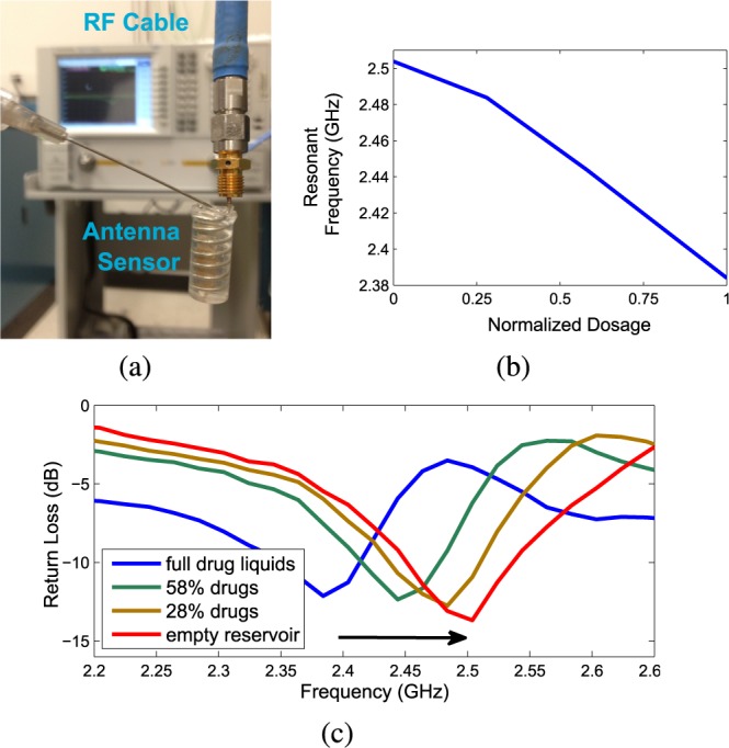
Fig. 8. In-vitro experiment on the dosage monitoring sensor for implanted drug delivery applications: (a). The experimental setup for an 8 turn helix antenna sensor loaded with solid drugs (resveratrol powders) inside a PBS solution surrounding environment. (b). The measured return loss of the sensor before and after the drugs released in the PBS solution.
B. Practical Design and Measurement Results
The simulation of Fig. 6 helps the antenna sensor design with PDMS package, while our practical designs are achieved through additional empirical adjustment. It is important to comply with Federal Communications Commission (FCC) regulations and only use the frequency bands that are allocated for medical applications. In this paper, for demonstration purpose, we target at the 2.4–2.5 GHz ISM band (the industrial, scientific and medical radio band). One transdermal drug delivery monitoring sensor and one implanted drug delivery monitoring sensor have been realized.
During the in-vitro experiment the sensor performance is more predictable in the air-surrounded environment than in the fluid-surrounded environment. The effect of surrounding liquid is difficult to be accurately represented in the simulation. For the implanted drug delivery monitoring demonstration, even though factors like the shape of the beaker, have all been included in the simulation, fine tuning of the feeding line and antenna parameters is still necessary during experiment. It can be expected that for in-vivo test and for real applications inside human body, the implanted antenna sensor design will be even more challenging.
The transdermal senors is a 4.9mm mm radius, 7-turn, 2.7 mm pitch gap helix with a 0.127 ml reservoir. It was designed to resonate at 2.4 GHz as the initial full liquid state and gradually shift up toward 2.5 GHz as the release process goes on. The kr value [17] of the antenna is 0.51, so the antenna is electrically small. The whole drug delivery procedure is a quasi-static process and the actual drug dosage in the reservoir is tractable throughout the experiment. The linearity of the antenna sensor is noticeable from the sensitivity curve shown in Fig. 7(b). Fig. 7(c) shows the measured  of the antenna sensor at four different dosage levels. The measured
  bandwidth of the antenna is 150 MHz (6.25% relative bandwidth) and sensitivity of the sensor is about 1.27
  .
.
The implanted sensor is a 4.8mm mm radius 8-turn 2.3mm mm pitch gap helix antenna (kr value is 0.50, also electrically small antenna) with a 0.221 ml reservoir, its picture is also shown in the middle of Fig. 5. The measurement results show that throughout the drug release the antenna resonance frequency shifts from 2.5 GHz down to 2.41 GHz as illustrated in Fig. 8(b). The measured  bandwidth of the antenna in the liquid surrounding environment is 110 MHz (4.58% relative bandwidth). The sensor linearity is not tested because in the fluid environment the drug release is driven by natural diffusion so that the actual drug dosage inside the reservoir is hardly tractable during the release process. The average sensitivity of this sensor for implanted drug delivery is about 2.76
  .
.
VI. Transceiver and Wireless Communication System for the Antenna Sensors
In the in-vitro test described in the previous section, test equipment like a network analyzer has been used for the comprehensive measurement of the antenna sensor performance. In practice, the complete system also need specifically designed low cost RFID reader and tag circuits integrated with the antenna sensor. Considering the fact that most controllable drug delivery devices also require some receiving antenna and receiver circuits for the drug delivery control, in this section a RFID tag circuit architecture is proposed to combine the functionalities of drug dosage monitoring transmitter and drug delivery control receiver.
As shown in Fig. 9, the antenna sensor itself is also served as a RFID tag antenna for the drug delivery control system. The power management unit contains some wake-up circuit to turn on the tag if it has a battery, or some energy harvesting circuit if it is completely relying on external power source. After the tag gets turned on, like any standard RFID system [25], the reader first sends some commends to identify the tag in which the identification information is stored in the state machine or memory unit. The central digital logic in the tag will then follow and generate some reply signal, which will be modulated and sent back to the reader through the helix antenna. During the next step, the reader will send commend to the tag to start monitoring the drug dosage level inside the tag drug capsule, and it will enable the frequency synthesizer to sweep the frequencies within the band of interest. The reader will then compare the received power at those frequencies and determine the tag antenna resonant frequency, which represents the drug dosage level. The detailed frequency synthesizer circuitry and sensor decision mechanism can be varied depends on the application precision requirements. The reader can also send commends to control the drug delivery process as the control unit is integrated.
Fig. 9. The proposed block diagram for the RFID tag circuits integrated with antenna sensor and drug delivery control.
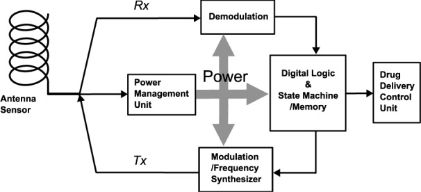
As both drug control unit and frequency synthesizer in the tag will be power consuming, comparing to general purpose RFID tags, the power budget for the RFID tag sensor/controller is more challenging. The state-of-art miniaturized battery technology, wireless powering technology, and ambient energy harvesting technology will help resolve such challenge and push the RFID drug delivery monitoring/control tag into practice. The detailed circuit level design and test of the RFID sensor tag is still in progress.
VII. Conclusion
This paper proposed the concept of using RFID tag helix antenna as a wireless sensor to directly track the drug dosage inside a reservoir integrated with the antenna sensor. The sensor was designed based on cavity resonator perturbation theory and electromagnetic simulation using HFSS, fabricated with the PDMS packaged drug reservoir by utilizing a low cost molding process with the help of selective laser sintering, and tested in-vitro using a Agilent PNA network analyzer. The measurement results have shown high sensitivity and good linearity. Tag circuit block diagram is also specifically designed to be integrated with the antenna sensor and some drug delivery control unit. Such tag sensor/controller can be used as a multifunctional node in the wireless health networks.
Acknowledgement
The authors would like to thank Mark Philips from Department of Mechanical Engineering at the University of Texas at Austin for selective laser sintering technical support.
Biographies

Haiyu Huang (S'07) received the M.Sc. degree in electrical engineering from Columbia University, New York, NY, in 2008. He is currently pursuing the Ph.D. degree in electrical and computer engineering from the University of Texas at Austin, and also a Research Assistant with the Methodist Hospital Research Institute. His research interests include wireless medical telemetry and novel nanoelectronic devices for healthcare applications.

Peisen Zhao (S'12) is currently pursuing the Ph.D. degree with the University of Texas at Austin. He received the B.S. degree in electronic engineering from Tsinghua University in 2013. His current research interests include biomedical instrumentation and high-throughput screen enabled by microfluidic technology.

Pai-Yen Chen (S'09–M'13) is a Research Scientist with the Intellectual Venture Laboratories, Bellevue, WA, USA. He received the Ph.D. degree in electrical and computer engineering from the University of Texas at Austin in 2013, and the B.S. and M.S. degrees in mechanical engineering (major) and electrooptical engineering from the National Chiao Tung University, Taiwan, in 2004 and 2006, respectively. From 2006 to 2009, he was an Assistant Researcher with the National Nano Device Laboratories, Taiwan.
His research interests include various topics in physical and wave electronics, including high-frequency electronics, electromagnetism, active and passive antennas, metamaterials, plasmonics, nanophotonics, and vacuum/solid-state nanoelectronic devices. He has co-edited a scientific book and authored over 70 referred papers in peer-reviewed journals and conference proceedings and several book chapters on these topics. He has organized and chaired several special sessions in International symposia and conferences. He was officially nominated a Chinese Phi Tau Phi Honorable Member in 2006. He was the recipient of the United Microelectronics Corporation Scholarship in 2005, the Honorable Mention Student Contest Award from the IEEE Antennas and Propagation Symposium in 2010, and the finalist in the same conference in 2011 and 2013, the Study Aboard Award from Taiwan Ministry of Education in 2010, the 3rd Prize Student Contest Award in Metamaterials Congress in 2011, the 3rd Prize Student Contest Award in USNC-URSI National Radio Science Meeting in 2012, and the Donald D. Harrington Dissertation Fellowship and Professional Development Award from the University of Texas at Austin in 2012 and 2013, respectively.

Yong Ren (M'11) received the B.S., M.S., and Ph.D. degrees in electronic engineering from the Harbin Institute of Technology, China, in 1984, 1987, and 1994, respectively. He was a Post-Doctor with the Department of Electrical Engineering, Tsinghua University, China, from 1995 to 1997. He is currently a Professor and the Director of the Complex Engineered System Laboratory, Tsinghua University. He holds 15 patents, and has authored and co-authored over 120 technical papers in Internet complexity, and P2P network and wireless communication. He has served as the Reviewer of the IEEE and IEICE Transactions, Chinese Physics, Chinese Journal of Electronics. His research interests include the complexity of the body area network, Internet information sharing, wireless extension of mobile terminals, and architecture of IoT with the mobile gateways.

Xuewu Liu was an Assistant Professor of nanomedicine and biomedical engineering with the University of Texas Health Science Center, Houston, in 2006. In 2010, he was with the Methodist Hospital Research Institute, to develop a nanoengineering core facility. His research focus is the development of silicon-based nanotechnology platforms for prevention, diagnosis, and treatment of human disease. His current interests include mass production of porous silicon particles, surface chemistry of porous silicon, nanowire theranostic platforms, multifunctional nanoparticles, and microfluidics devices for isolation and analysis of exosomes.

Mauro Ferrari serves as the President and CEO of the Houston Methodist Research Institute, where he holds the Ernest Cockrell Jr. Distinguished Endowed Chair. He is also the Director of the Institute of Academic Medicine and the Executive Vice President of Houston Methodist, and is the President of the Alliance for NanoHealth, Houston.

Ye Hu received the Ph.D. degree in biomedical engineering from the University of Texas at Austin in 2009. He is currently an Assistant Member of the Methodist Hospital Research Institute. He directs a nanomedicine research program focusing on the development of novel nanomaterials and nanodevices, and their applications to biomarker detection.

Deji Akinwande (M'98-SM'13) received the B.S. degree in electrical engineering and the M.S. degree in applied physics from Case Western Reserve University, Cleveland, OH, USA, and the Ph.D. degree in electrical engineering from Stanford University, Stanford, CA, USA, where he conducted research on the experimental synthesis, device physics, and circuit applications of carbon nanotubes and graphene. His master's research involved the design, development, and characterization of evanescent microwave probes for nondestructive imaging of materials. He is currently an Assistant Professor with the University of Texas, Austin. He is a Co-Inventor of a high-frequency bondwire interconnect. He has been honored with the inaugural IEEE Nano Geim and Novoselov Graphene Prize, the NSF CAREER Award, the Army and DTRA Young Investigator Awards, the 3M Nontenured Faculty Award, and was a past recipient of the 2005 Stanford Cheesy Award for outstanding LNA design and the Ford Foundation, Alfred P. Sloan Foundation, and Stanford DARE Fellowships.
Funding Statement
The authors would like to thank Mark Philips from Department of Mechanical Engineering at the University of Texas at Austin for selective laser sintering technical support.
References
- [1].Kerbel R. S. and Kamen B. A., “The anti-angiogenic basis of metronomic chemotherapy,” Nature Rev. Cancer, vol. 4, no. 6, pp. 423–436, 2004. [DOI] [PubMed] [Google Scholar]
- [2].Fine D., Grattoni A., Zabre E., Hussein F., Ferrari M., and Liu X., “A low-voltage electrokinetic nanochannel drug delivery system,” Lab Chip, vol. 11, no. 15, pp. 2526–2534, Aug. 2011. [DOI] [PubMed] [Google Scholar]
- [3].Fine D., et al. , “A robust nanofluidic membrane with tunable zero-order release for implantable dose specific drug delivery,” Lab Chip, vol. 10, no. 22, pp. 3074–3083, Nov. 2010. [DOI] [PubMed] [Google Scholar]
- [4].Yang Y.-J., et al. , “A release-on-demand wireless CMOS drug delivery SoC based on electrothermal activation technique,” in IEEE Int. Solid-State Circuits Conf., Dig. Tech. Papers, Feb. 2009, pp. 288–289. [Google Scholar]
- [5].Mansoor I., Hafeli U. O., and Stoeber B., “Arrays of solvent cast hollow out-of-plane polymer microneedles for drug delivery,” in Proc. IEEE 24th Int. Conf. Micro Electro Mech. Syst. (MEMS), Cancun, Mexico, Jan. 2011, pp. 1027–1030. [Google Scholar]
- [6].Rahimi S., Sarraf E. H., Wong G., and Takahata K., “Implantable drug delivery device using frequency-controlled wireless hydrogel microvalves,” Biomed. Microdevices, vol. 13, no. 2, pp. 267–277, Apr. 2011. [DOI] [PubMed] [Google Scholar]
- [7].Woods S. P. and Constandinou T. G., “Wireless capsule endoscope for targeted drug delivery: Mechanics and design considerations,” IEEE Trans. Biomed. Eng., vol. 60, pp. 945–953, Apr. 2013. [DOI] [PubMed] [Google Scholar]
- [8].Rajian J., Fabiilli M., Fowlkes J., Carson P., and Wang X., “Drug delivery monitoring by photoacoustic tomography with an ICG encapsulated double emulsion,” Opt. Exp., vol. 19, no. 15, pp. 14335–14347, Jul. 2011. [DOI] [PMC free article] [PubMed] [Google Scholar]
- [9].Lurie D. J. and Mäder K., “Monitoring drug delivery process by EPR and related techniques-principles and applications,” Adv. Drug Delivery Rev., vol. 57, no. 8, pp. 1171–1190, 2005. [DOI] [PubMed] [Google Scholar]
- [10].Weinstain R., Segal E., Satchi-Fainaro R., and Shabat D., “Real-time monitoring of drug release,” Chem. Commun., vol. 46, no. 4, pp. 553–555, 2010. [DOI] [PubMed] [Google Scholar]
- [11].in MiniMed insulin pump therapy, Scottsdale, AZ USA: MiniMed, 2013, [Online]. Available: http://www.medtronicdiabetes.com/. [Google Scholar]
- [12].in Empi action patch, 2013, [Online]. Available: http://www.empi.com/.
- [13].in Smart Pill, Smart Pill: Yokneam, Israel, 2012, [Online]. Available: http://www.smartpillcorp.com/. [Google Scholar]
- [14].in Philips iPill, 2008, [Online]. Available: http://www.research.philips.com/.
- [15].MicroCHIPS' Drug Delivery Device, Scottsdale, AZ USA: MicroCHIPS, 2013, [Online]. Available: http://www.mchips.com/. [Google Scholar]
- [16].Cho N., Bae J., and Yoo H.-J., “A 10.8 mW body channel communication/MICS dual-band transceiver for a unified body sensor network controller,” IEEE J. Solid-State Circuits, vol. 44, pp. 3459–3468, Dec. 2009. [Google Scholar]
- [17].Balanis C. A., Antenna theory: Analysis and design, 3rd ed., New York, NY USA: Wiley, 2005. [Google Scholar]
- [18].Bianco B., Drago G. P., Marchesi M., Martini C., Mela S., and Ridella S., “Measurements of complex permittivity of human sera and erythrocytes,” IEEE Trans. Instrum. Meas., vol. 28, pp. 290–295, Dec. 1979. [Google Scholar]
- [19].Pozar D. M., Microwave Engineering, 3rd ed., New York, NY USA: Wiley, 2005. [Google Scholar]
- [20].Chen P. Y., Monticone F., and Alu A., “Suppressing the electromagnetic scattering with an helical mantle cloak,” IEEE Antenna Wireless Propag. Lett., vol. 10, no. 4, pp. 1598–1601, Dec. 2011. [Google Scholar]
- [21].in Ansys HFS, Ansys HFS: Irvine, CA USA, 2012, [Online]. Available: http://www.ansys.com/. [Google Scholar]
- [22].Adams J. J., et al. , “Conformal printing of electrically small antennas on three-dimensional surfaces,” Adv. Mater., vol. 23, no. 11, pp. 1335–1340, Mar. 2011. [DOI] [PubMed] [Google Scholar]
- [23].Huang H., Nieman K., Chen P., Ferrari M., Hu Y., and Akinwande D., “Properties and applications of electrically small folded ellipsoidal helix antenna,” IEEE Antennas Wireless Propag. Lett., vol. 11, no. 1, pp. 678–681, Jun. 2012. [Google Scholar]
- [24].Guo L., Meacham K. W., and DeWeerth S. P., “A PDMS-based conical-well microelectrode array for surface stimulation of neural tissues,” IEEE Trans. Biomed. Eng., vol. 57, pp. 2485–2494, Oct. 2010. [DOI] [PMC free article] [PubMed] [Google Scholar]
- [25].Rida A., Yang L., and Tentzeris M., RFID-Enabled Sensor Deisgn and Applications, Norwood, MA USA: Artech House, 2010. [Google Scholar]


