

Abstract
Comparisons of the focusing properties for the radially and azimuthally polarized beams with different pupil functions, such as uniform, Gaussian and Bessel-Gauss profiles, are presented. The results show that, for any pupil function, the spot sizes of the azimuthally polarized beam modulated with the vortex-0-2π-phase plate or the π-phase-step plate are smaller than that of the radially polarized beam encoded with or without these two types of plates. Then a type of multi-zone phase plate for generating tighter multifocal arrays from azimuthally polarized beams is proposed. The position and the linear polarization of the multifocal spots can be controlled by varying the pattern of the multi-zone phase plate and rotating the direction of the π-phase-step plate. In addition, for the radially polarized beam with Gaussian or Bessel-Gauss profiles and with the specified ratio of pupil diameter to beam diameter, the focal spot can be further reduced after modulated with the vortex-0-2π-phase plate, and the focal spot will be split into two after modulated with the π-phase-step plate. The latter property can be used to double the efficiency of parallel micro-manipulation.
Tight focusing of the kinds of polarized vector beams has aroused wide interests over the last decade due to its versatile properties, especially for unconventional polarization beams such as cylindrical vector [1-5] and hybrid polarization beams [6-8]. Radially and azimuthally polarized beams are two important types of cylindrical vector. While a tight circular focal spot is generated directly from a radially polarized beam, only a donut focal spot can be produced from an azimuthally polarized beam [4]. However, versatile focal spot can be produced with special phase modulation.
For example, an optical needle was produced from radially polarized beams by using a binary phase pupil filter [9, 10], or from an azimuthally polarized beam with a double-ring shape [11]. To produce a tight circular focal spot from the azimuthally polarized beam, a vortex-0-2π-phase plate was employed to encode the beam and to make the interference constructive along each radial direction [5, 12, 13]. The resulted focal spot is circularly shaped and the electric field in the focal plane is mixed with circularly and elliptically polarized states. Similarly, a π-phase-step plate is also used to produce a tight focal spot from the radially and azimuthally polarized vectors. The resulted focal spot is elliptically shaped and has a linearly polarized state [14, 15]. The size of the focal spot is narrowed across the polarization direction. For the azimuthally polarized beam, the linear polarization direction is parallel to the π-phase-step line. In contrast, the linear polarization direction is perpendicular to the π-phase-step line for the radially polarized beam. The focal spots with different orientations of linear polarization can be generated by varying the orientation of the phase-step line.
Recently, the method for simultaneously generating multifocal array, especially producing multifocal array with controllable position and polarization, has becomes an interesting subject [16-18]. It has many potential applications in the fields of parallel fabrication of polarization sensitive photonic devices, parallel optical recording, multi-dimensional optical data storage, parallel polarization optical imaging, and dynamic parallel optical manipulation. Ren et al. [15] used a programmable spatial light modulator to encode the π-phase-step plates in the four quadrants of an azimuthally polarized beam and produced four focal spots withdifferent polarization directions. To producemore focal spots with controllable position and polarization, Zhu et al. [19] designed a type of multi-zone plate for radially polarized Bessel-Gaussian beam according to the Fourier analytical form of Richards–Wolf integral. Comparedto the complex iterative algorithmsneeded in the spatial light modulator, it is easier to control focal position and polarization with the multi-zone plate.
In this paper, we will extend the latter method for the azimuthally polarized beam. A type of multi-zone plate is designed and combined with a vortex-0-2π-phase plate or π-phase-step plates to produce a multifocal array with controllable position and polarization. The main reasons are that pure-transverse focal fields with enhanced energy density can be obtained by focusing azimuthally polarized beam [13]. The spot size of the azimuthally polarized beam with any pupil function, modulated with the vortex-0-2π-phase plate or the π-phase-step plate, are smaller than that of the radially polarized beam modulated with or without these two types of plates. This point will be detailed in the following text.
As shown in Fig. 1, the electric field in the focal region Q (ρ, φf, z) of an aplanatic objective formed by linearly polarized illumination can be expressed using Richards and Wolf integral as [20]
| (1) |
Fig. 1.
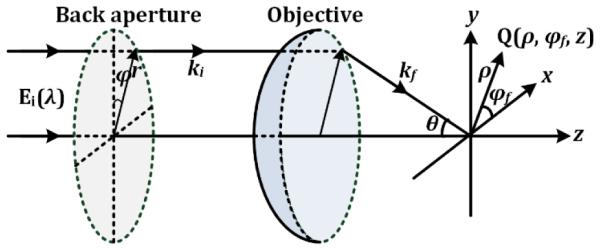
The geometry for the focusing of the incident polarized beam.
where A is a complex constant related to the focal length f of the objective and wavelength, k = 2π/λ is wavenumber, (ρ, φf , z) are the cylindrical coordinates in focal volume, (r, φ) are polar coordinates at the back aperture plane, θ = arcsin [r·NA/(n·rmax)] is the aperture angle of the objective, rmax and θmax are the maximum aperture and aperture angle of the objective, n is refractive index in focal volume, NA is the numerical aperture of the objective; Ei is the electric vector of incident beam, M(θ, φ) is a 3×3 focusing matrix, and P(θ) is pupil function for incident light. The pupil function can be uniform (PU), Gaussian (PG), or Bessel-Gauss (PBG) profiles, and these functions with their waists in the pupil can be expressed as, respectively [3],
| (2a) |
| (2b) |
| (2c) |
where β is the ratio of the pupil diameter to the beam diameter, J1 is Bessel function of the first order. Most previous research [1-5, 9-15] only checked special values of βG and βBG, so the resulted conclusions are limited and many important focusing properties will be missed.
In this letter, we will first compare the focusing properties of the radially and azimuthally polarized beams with different pupil functions such as radially polarized uniform (RPU) beam, radially polarized Gaussian (RPG) beam, radially polarized Bessel-Gauss (RPBG) beam, azimuthally polarized uniform (APU) beam, azimuthally polarized Gaussian (APG) beam, and azimuthally polarized Bessel-Gauss (APBG) beam. Specially, some of them will be modulated with the vortex-0-2π-phase plate or the π-phase-step plate. The calculations of the integral in Eq. (1) are performed numerically by using the parameters λ = 532 nm, NA = 1.4, and n = 1.518. After getting the full width at half maximum (xFWHF and yFWHF) of the focal spot along x and y directions, the spot area can be calculated with π × xFWHF/2 × yFWHF/2 and shown in Fig. 2.
Fig. 2.
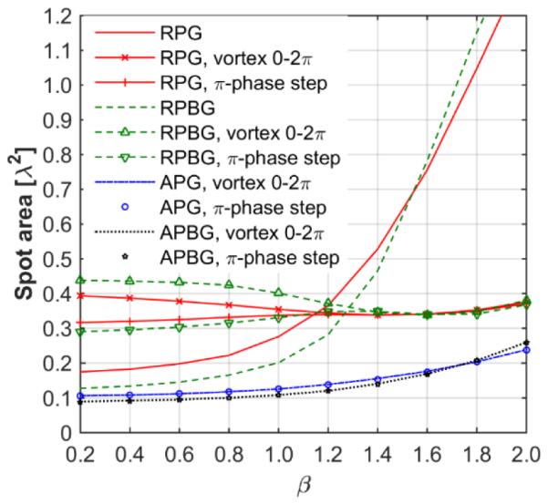
The spot sizes of the radially and azimuthally polarized beams with Gaussian or Bessel-Gauss profiles, after modulation by different phase plates, vary with the ratio β of the pupil diameter to the beam diameter
Obviously, for the Gaussian and Bessel-Gauss beam profiles, the spot areas of the azimuthally polarized beam modulated by two types of plates are smaller than the radially polarized beam modulated with or without two types of plates. Furthermore, following properties are also interesting for different focusing beams.
The spot size of RPG beam modulated by the vortex 0-2π-phase plate is smaller than pure RPG beam when β ≥ 1.2. The spot size of RPG beam modulated by the π-phase-step plate is smaller than that of pure RPG beamor RPG beam modulated by thevortex 0-2π phase plate. It is noted that two peaks will be generated from the RPG beam modulated by the π-phase-step plate when β ≤ 1.1, and both of them are linearly polarized fields with the same polarization direction, as show in Fig. 3(a). The two peaks will become more distinguished with the decrease of β. Two distinguishable peaks can be used to manipulate two particles simultaneously for improving parallel efficiency. The spot areas of RPBG beam modulated by the two type of plates are smaller than pure RPBG beam when β >1.3. However, annular peak will be produced from the pure RPBG beam when β ≥ 1.8, or from the RPBG beam modulated by the vortex 0-2π-phase plate when β ≤ 0.8, as shown in Fig. 3(b). Similarly, two peaks will be generated from the RPBG beam modulated by the π-phase-step plate when β ≤ 1.3, and they also will become more distinguished with the decrease of β as shown in Fig. 3(c). The spot sizes of APG (or APBG) beam modulated by the two types of plates are similar to each other. The spot sizes of the modulated APBG beam is smaller than the modulated APG beam when β ≤ 1.8. However, by comparing Figs. 3(d) and 3(e), the side-lobe intensities of the modulated APBG beam are a bit high and increase with the decrease of β.
Fig. 3.
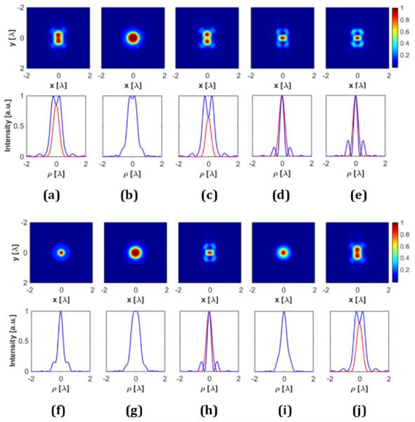
The focal spots (upper) and profiles (lower) of different beams: (a) RPG, (c) RPBG, (d) APG and (e) APBG beams modulated by the π-phase-step plate, and (b) RPBG beam modulated by the vortex 0-2π phase plate, where β = 0.5; (f) pure RPU beam, (g) RPU and (h) APU beams modulated by the vortex 0-2π phase plate, and (i) RPU and (j) APU beams modulated by the π-phase-step plate.
In Figs. 3(f)-3(i), the spot areas of RPU beam modulated by the two types of plates become larger than that of pure RPU. Furthermore, two peaks are generated from the RPU beam modulated by the π-phase-step plate. In contrast, the spot areas of APU beam modulated by the two type of plates are only 0.1λ2, it is smaller than that of pure RPU beam, even APBG beam modulated by the two types plates when β >1.0. Furthermore, for the radially polarized vector, the focal spot of RPU beam is smallest, the RPBG beam with β = 1.5 is worst, and the RPG beam with β = 1.26 is moderate. This result is similar to that in reference [3]. For the azimuthally polarized vector modulated with the vortex 0-2π phase plate, the APBG with β = 0.5 is best, the APG with β = 0.5 is worst, and the APU is moderate. The result is the same to that in references [5, 12]. However, these phenomena cannot be preserved for other values of β.
As shown, the azimuthally polarized beams with different profiles modulated by the two types of plates are the best choices to get tighter focal spot under the condition of without considering the side-lobe intensity. Although the above focusing properties are generated at the special parameters of objective, they are also adapted to the objective with different NA, refractive index n, or wavelength, the only change will be the inflection points of β.
To produce multifocal array analytically, the Richards and Wolf integral in Eq. (1) should be rewritten as a Fourier transform of the weighted field Et with a vector angular spectrum form [19, 21],
| (3) |
where F { · } indicates Fourier transform, ξ = −ncosφsinθ/λ and η = −nsinφsinθ/λ. Therefore the lateral displacement (Δx, Δy) ofthe focal spot can be performed by forcing the phase shift in the incident field as
| (4) |
Therefore, combining the multiply specified phase shift in Eq. (4) with the vortex-0-2π-phase plate or the π-phase-step plate, tighter multifocal array with controllable position and polarization can be produced from the azimuthally polarized beam.
Different from the multi-zone phase plate designed for the radially polarized beam in reference [19], special attention should be paid to the phase modulation for the azimuthally polarized beam. The azimuthal polarization in each zone of multi-zone phase plate should be preserved first, so the above mentioned tight focusing properties can be maintained. Each zone is then modulated with the same vortex 0-2π phase plate or combined with the diverse π-phase step plates. As shown in Fig. 4, the back aperture of the objective in Fig. 1 is divided into N annuli, and each annulus is then divided into M smaller annuli, where N and M are positive integers. Each smaller annulus can be divided with the same aperture angle interval, with the same area, or with the same intensity according to the pupil function. Regardless of the method, there will be an optimal configuration that can produce multifocal array with high relative uniformity, since each annulus occupies different aperture angle that mainly determines the distributions of the focal intensity. The cost function for the uniformity is needed for optimization and is defined as χ = argmax {2Imin/(Imax+Imin)}, where Imax and Imin represent the maximum and minimum intensity in foci. The optimal configuration can be obtained within a limited annuli number N. Fewer annuli is recommended for subsequent fabrication. This is different from that in reference [19] where the aperture angel of each fan is similar and then the uniformity increases with the number N.
Fig. 4.
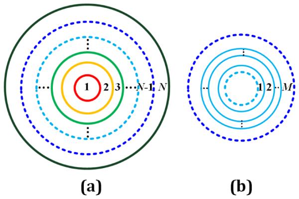
Configuration of multi-zone phase plate. (a) The back aperture of the objective is divided into N annuli, and (b) the annulus formed with two dotted lines in (a) is then divided into M smaller annuli.
To verify the proposed method, several types of multi-zone phase plates will be designed for APG beam with β = 0.5, because tighter focal spot with a relatively low sidelobe can be generated from this beam as stated in Fig. 2 and Fig, 3. Herein, each smaller annulus is divided with the same area. First, a type of multi-zone phase plate that work with the vortex 0-2π phase plate are designed. While the multi-zone phase plate produces multifocal array, the vortex 0-2π phase plate translates each donut focal spot into circular focal spot. Fig. 5(a) shows the phase pattern of an optimal multi-zone phase plate with M=4 and N=16. The lateral shifts of the four focal spots are [(2, 2), (2, −2), (−2, 2) (−2, −2)] λ. The uniformity of the focal array is approximately 96%. If high uniformity is required, a wider range of annuli number N should be explored. For example, the uniformity will become 98% when N = 40. Fig. 5(b) shows the multi-zone phase plate with M=5 and N=23. Different from that in Fig. 5(a), the black center means that there is no additional phase shift for the central focal spot. The lateral shifts of the five focal spots are [(0, 0), (0, 2), (0, −2), (2, 0) (−2, 0)] λ. The uniformity is approximately 94%. Fig. 5(c) shows the multi-zone phase plate with M=7 and N=17. The locations of seven focal spots are (0, 0) and [Δx=2λcos(mπ/3). Δx=2λsin(mπ/3), m= 1, 2 … 6]. The uniformity is approximately 92%.
Fig. 5.

The patterns of the designed multi-zone phase plates (upper) and the corresponding multifocal arrays (lower) with controllable position and polarization that generated from the APG beam with β = 0.5. The configuration of the multi-zone phase plats are (a) M=4, N=16, (b) M=5, N=23, (c) M=7, N=17, (d) M=4, N=16, (e) M=5, N= 15, (f) M=7, N=17. While there are only phase shift in the mulit-zone phase plates (a)-(c), there are additional π-phase step in (d)-(f). The straight line, circle and ellipse on the multifocal array indicate linear, circular and elliptic polarization states respectively.
Second, a type of multi-zone phase plate that combines with diverse π-phase step plates are designed, which means π-phase step with diverse step line direction are added into each smaller annulus for controlling the linear polarization direction of each focus. Fig. 5(d) shows the phase pattern of an optimal multi-zone phase plate with M=4 and N=16. The uniformity of the corresponding multifocal array is 96%. As can be seen, the polarization directions in the four foci are oriented at different specified direction. Fig. 5(e) and 5(f) shows the multi-zone phase plates with M=5, N=15 and M=7, N=17. Half of the center is not black due to the additional π-phase step shift. The uniformities of the multifocal array are 95% and 92%, respectively. As can be seen, our proposed method can produce tighter multifocal arrays with controllable position and polarization from the azimuthally polarized beam than that from the radially polarized beam.
In fact, the proposed multi-zone phase plates are also adapted to the radially polarized beam, because the radial polarization states in each annulus are also preserved. Fig. 6(a) shows the multifocal array generated from the RPBG with β = 0.5 and the used multi-zone plate is similar to that in Fig. 5(c) and 5(f). The uniformities are approximately 94% and 83%. Although the polarization state in Fig. 6(a) is linear, it is uncontrollable, just determined from the state of incident beam. The uniformity in Fig. 6(b) increases to 92% for N=40 as shown in Fig. 6(c). Especially, in Fig. 6(b) and 6(c), each focal spot consists of two foci, the parallel efficiency is two times of previously reported multifocal arrays.
Fig. 6.
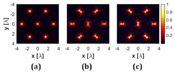
The multifocal arrays with controllable position and polarization that produced from RPBG beam with β = 0.5. The multi-zone plates used in (a) and (b) are similar to that in Fig. 5(e) and 5(f) respectively. The multi-zone plate used in (c) increase to N=40.
In conclusion, diverse focusing properties of the radially and azimuthally polarized beams with different pupil functions (such as uniform, Gaussian, and Bessel-Gauss profiles) that modulated with the vortex 0-2π phase plate or the π-phase step plate are explored. Azimuthally polarized beam produce tighter focal spot with any pupil function. A type of multi-zone phase plate to produce tighter multifocal array is proposed for the azimuthally polarized beams, which is also applicable to the radially polarized beams. The produced multifocal array with controllable position and polarization will be beneficial to the parallel optical micro-manipulation.
Acknowledgments
Funding. The China Scholarship Council (201406285048), the Fundamental Research Funds for the Central Universities of China (xjj2013044), the Specialized Research Fund for the Doctoral Program of Higher Education of China (20130201120047), the Natural Science Basic Research Plan in Shaanxi Province of China (2014JQ8362), the National Natural Science Foundation (61405153, 61275184, 41530422) of China, and the 863 Program (2012AA121101) of China.
References
Set references at the back of the manuscript. Optics Letters uses an abbreviated reference style. Citations to journal articles should omit the article title and final page number. However, full references (to aid the editor and reviewers) must be included as well on a fifth page that will not count against page length.
- 1.Youngworth K, Brown T. Opt. Express. 2000;7:77. doi: 10.1364/oe.7.000077. [DOI] [PubMed] [Google Scholar]
- 2.Dorn R, Quabis S, Leuchs G. Phys. Rev. Lett. 2003;91:233901. doi: 10.1103/PhysRevLett.91.233901. [DOI] [PubMed] [Google Scholar]
- 3.Yew EYS, Sheppard CJR. Opt. Lett. 2007;32:3417. doi: 10.1364/ol.32.003417. [DOI] [PubMed] [Google Scholar]
- 4.Zhan Q. Adv. Opt. Photonics. 2009;1:1–57. [Google Scholar]
- 5.Cheng Z, Zhou Y, Xia M, Li W, Yang K, Zhou Y. Opt. Laser Tech. 2015;73:77. [Google Scholar]
- 6.Beckley AM, Brown TG, Alonso MA. Opt. Express. 2010;18:10777. doi: 10.1364/OE.18.010777. [DOI] [PubMed] [Google Scholar]
- 7.Lerman GM, Stern L, Levy U. Opt. Express. 2010;18:27650. doi: 10.1364/OE.18.027650. [DOI] [PubMed] [Google Scholar]
- 8.Wang XL, Chen J, Li Y, Ding J, Guo CS, Wang HT. Phys. Rev. Lett. 2010;105:253602. doi: 10.1103/PhysRevLett.105.253602. [DOI] [PubMed] [Google Scholar]
- 9.Wang H, Shi L, Lukyanchuk B, Sheppard C, Chong CT. Nat Photon. 2008;2:501. [Google Scholar]
- 10.Guo H, Weng X, Jiang M, Zhao Y, Sui G, Hu Q, Wang Y, Zhuang S. Opt. Express. 2013;21:5363. doi: 10.1364/OE.21.005363. [DOI] [PubMed] [Google Scholar]
- 11.Tian B, Pu J. Opt. Lett. 2011;36:2014. doi: 10.1364/OL.36.002014. [DOI] [PubMed] [Google Scholar]
- 12.Hao X, Kuang C, Wang T, Liu X. Opt. Lett. 2010;35:3928. doi: 10.1364/OL.35.003928. [DOI] [PubMed] [Google Scholar]
- 13.Li X, Venugopalan P, Ren H, Hong M, Gu M. Opt. Lett. 2014;39:5961. doi: 10.1364/OL.39.005961. [DOI] [PubMed] [Google Scholar]
- 14.Khonina SN, Golub I. Opt. Lett. 2011;36:352. doi: 10.1364/OL.36.000352. [DOI] [PubMed] [Google Scholar]
- 15.Ren H, Li X, Gu M. Opt. Lett. 2014;39:6771. doi: 10.1364/OL.39.006771. [DOI] [PubMed] [Google Scholar]
- 16.Gu M, Lin H, Li X. Opt. Lett. 2013;38:3627–3630. doi: 10.1364/OL.38.003627. [DOI] [PubMed] [Google Scholar]
- 17.Ren H, Lin H, Li X, Gu M. Opt. Lett. 2014;39:1621–1624. doi: 10.1364/OL.39.001621. [DOI] [PubMed] [Google Scholar]
- 18.You S, Kuang C, Toussaint KC, Zhou R, Xia X, Liu X. Opt. Lett. 2015;40:3532. doi: 10.1364/OL.40.003532. [DOI] [PubMed] [Google Scholar]
- 19.Zhu L, Sun M, Zhang D, Yu J, Wen J, Chen J. Opt. Express. 2015;23:24688–24698. doi: 10.1364/OE.23.024688. [DOI] [PubMed] [Google Scholar]
- 20.Richards B, Wolf E. Proc. R. Soc. Lond. A Math. Phys. Sci. 1959;253:358. [Google Scholar]
- 21.Leutenegger M, Rao R, Leitgeb RA, Lasser T. Opt. Express. 2006;14:11277. doi: 10.1364/oe.14.011277. [DOI] [PubMed] [Google Scholar]
- 22.Youngworth K, Brown T. Focusing of high numerical aperture cylindrical-vector beams. Opt. Express. 2000;7:77–87. doi: 10.1364/oe.7.000077. [DOI] [PubMed] [Google Scholar]
- 23.Dorn R, Quabis S, Leuchs G. Sharper Focus for a Radially Polarized Light Beam. Phys. Rev. Lett. 2003;91:233901. doi: 10.1103/PhysRevLett.91.233901. [DOI] [PubMed] [Google Scholar]
- 24.Yew EYS, Sheppard CJR. Tight focusing of radially polarized Gaussian and Bessel-Gauss beams. Opt. Lett. 2007;32:3417–3419. doi: 10.1364/ol.32.003417. [DOI] [PubMed] [Google Scholar]
- 25.Zhan Q. Cylindrical vector beams: from mathematical concepts to applications. Advances in Optics and Photonics. 2009;1(1):1–57. [Google Scholar]
- 26.Cheng Z, Zhou Y, Xia M, Li W, Yang K, Zhou Y. Tight focusing of the azimuthally polarized light beam for a sharper spot. Optics & Laser Technology. 2015;73:77–81. [Google Scholar]
- 27.Beckley AM, Brown TG, Alonso MA. Full Poincare beams. Opt. Express. 2010;18:10777–10785. doi: 10.1364/OE.18.010777. [DOI] [PubMed] [Google Scholar]
- 28.Lerman GM, Stern L, Levy U. Generation and tight focusing of hybridly polarized vector beams. Opt. Express. 2010;18:27650–27657. doi: 10.1364/OE.18.027650. [DOI] [PubMed] [Google Scholar]
- 29.Wang X-L, Chen J, Li Y, Ding J, Guo C-S, Wang H-T. Optical orbital angular momentum from the curl of polarization. Phys. Rev. Lett. 2010;105:253602. doi: 10.1103/PhysRevLett.105.253602. [DOI] [PubMed] [Google Scholar]
- 30.Wang H, Shi L, Lukyanchuk B, Sheppard C, Chong CT. Creation of a needle of longitudinally polarized light in vacuum using binary optics. Nat Photon. 2008;2:501–505. [Google Scholar]
- 31.Guo H, Weng X, Jiang M, Zhao Y, Sui G, Hu Q, Wang Y, Zhuang S. Tight focusing of a higher-order radially polarized beam transmitting through multi-zone binary phase pupil filters. Opt. Express. 2013;21:5363–5372. doi: 10.1364/OE.21.005363. [DOI] [PubMed] [Google Scholar]
- 32.Tian B, Pu J. Tight focusing of a double-ring-shaped, azimuthally polarized beam. Opt. Lett. 2011;36:2014–2016. doi: 10.1364/OL.36.002014. [DOI] [PubMed] [Google Scholar]
- 33.Hao X, Kuang C, Wang T, Liu X. Phase encoding for sharper focus of the azimuthally polarized beam. Opt. Lett. 2010;35:3928–3930. doi: 10.1364/OL.35.003928. [DOI] [PubMed] [Google Scholar]
- 34.Li X, Venugopalan P, Ren H, Hong M, Gu M. Super-resolved pure-transverse focal fields with an enhanced energy density through focus of an azimuthally polarized first-order vortex beam. Opt. Lett. 2014;39:5961–5964. doi: 10.1364/OL.39.005961. [DOI] [PubMed] [Google Scholar]
- 35.Khonina SN, Golub I. Optimization of focusing of linearly polarized light. Opt. Lett. 2011;36:352–354. doi: 10.1364/OL.36.000352. [DOI] [PubMed] [Google Scholar]
- 36.Ren H, Li X, Gu M. Polarization-multiplexed multifocal arrays by a π-phase-step-modulated azimuthally polarized beam. Opt. Lett. 2014;39:6771–6774. doi: 10.1364/OL.39.006771. [DOI] [PubMed] [Google Scholar]
- 37.Gu M, Lin H, Li X. Parallel multiphoton microscopy with cylindrically polarized multifocal arrays. Opt. Lett. 2013;38:3627–3630. doi: 10.1364/OL.38.003627. [DOI] [PubMed] [Google Scholar]
- 38.Ren H, Lin H, Li X, Gu M. Three-dimensional parallel recording with a Debye diffraction-limited and aberration-free volumetric multifocal array. Opt. Lett. 2014;39:1621–1624. doi: 10.1364/OL.39.001621. [DOI] [PubMed] [Google Scholar]
- 39.You S, Kuang C, Toussaint KC, Zhou R, Xia X, Liu X. Iterative phase-retrieval method for generating stereo array of polarization-controlled focal spots. Opt. Lett. 2015;40:3532–3535. doi: 10.1364/OL.40.003532. [DOI] [PubMed] [Google Scholar]
- 40.Zhu L, Sun M, Zhang D, Yu J, Wen J, Chen J. Multifocal array with controllable polarization in each focal spot. Opt. Express. 2015;23:24688–24698. doi: 10.1364/OE.23.024688. [DOI] [PubMed] [Google Scholar]
- 41.Richards B, Wolf E. Electromagnetic diffraction in optical systems II. Structure of the image field in an aplanatic system. Proc. R. Soc. Lond. A Math. Phys. Sci. 1959;253:358–379. [Google Scholar]
- 42.Leutenegger M, Rao R, Leitgeb RA, Lasser T. Fast focus field calculations. Opt. Express. 2006;14:11277–11291. doi: 10.1364/oe.14.011277. [DOI] [PubMed] [Google Scholar]