Abstract
Objective
Lower limb amputees are at high risk of falling as current prosthetic legs provide only limited functionality for recovering balance after unexpected disturbances. For instance, the most established control method used on powered leg prostheses tracks local joint impedance functions without taking the global function of the leg in balance recovery into account. Here we explore an alternative control policy for powered transfemoral prostheses that considers the global leg function and is based on a neuromuscular model of human locomotion.
Methods
We adapt this model to describe and simulate an amputee walking with a powered prosthesis using the proposed control, and evaluate the gait robustness when confronted with rough ground and swing leg disturbances. We then implement and partially evaluate the resulting controller on a leg prosthesis prototype worn by a non-amputee user.
Results
In simulation, the proposed prosthesis control leads to gaits that are more robust than those obtained by the impedance control method. The initial hardware experiments with the prosthesis prototype show that the proposed control reproduces normal walking patterns qualitatively and effectively responds to disturbances in early and late swing. However, the response to mid-swing disturbances neither replicates human responses nor averts falls.
Conclusions
The neuromuscular model control is a promising alternative to existing prosthesis controls, although further research will need to improve on the initial implementation and determine how well these results transfer to amputee gait.
Significance
This work provides a potential avenue for future development of control policies that help improve amputee balance recovery.
Index Terms: Powered prosthesis, neuromuscular model, prosthesis control, transfemoral prosthesis
I. INTRODUCTION
There are currently an estimated six hundred thousand lower-limb amputees in the United States, a number expected to rise in the coming decades due to a growing diabetes epidemic [1]. A major problem that confronts this population is falls, which can cause bodily harm and trigger a fear of physical activity. This issue especially affects transfemoral amputees due to limited actuation and control in commercial prostheses. For instance, manufacturers have released a number of prosthetic devices such as the Ottobock C-leg and the Ossur Rheo Knee [2], which employ microprocessor-controlled knee dampers that improve steady gait characteristics over passive mechanical prostheses. However, without active components, these products cannot match the performance of human limbs as they cannot generate positive net work over a gait cycle. Consequently, transfemoral amputees wearing these prostheses suffer from increased energy consumption, slower ambulation speeds, and a limited ability to respond to unexpected disturbances such as trips, slips and pushes [3], [4].
To address the kinematic, energetic, and robustness problems caused by mechanical-passivity, researchers have developed powered knee-ankle prostheses and controllers that generate desired walking motions. One recent example is Vanderbilt University’s powered lower limb prosthesis [5]–[7], which features motors at both the ankle and knee joints that enable it to generate positive net work over a gait cycle. Research efforts have produced several control methods for this prosthesis: One such method is quasi-stiffness control, which uses the torque versus angle relationships seen during intact walking to produce torque references for the prosthesis. This control strategy can also achieve speed adaptation via interpolation between two sets of quasi-stiffness profiles, one for slow walking and one for fast walking [8]. Another method, minimum jerk swing control, uses the estimated swing duration and the joint angles and velocities at toe off to generate smooth torque trajectories that dorsiflex the ankle, flex the knee in order to achieve ground clearance, and then extend the knee before heel strike [9]. Finally, virtual constraint control enforces biomimetic ankle-foot and knee-ankle-foot rollover shapes via a partial feedback linearizing controller [10].
The most established control method used on this and similar powered prostheses is impedance control. This strategy uses piecewise impedance functions to approximate the torque versus joint angle relationships for each phase of the intact human gait cycle. With this control method, Sup and colleagues produced joint angles and torques for the knee and ankle similar to those seen during normal, level-ground walking [7]. However, they also found that the required impedance functions vary greatly with the environment [11] and need to be augmented with a separate stumble classifier and recovery controller to react to disturbances [12].
An alternative approach to joint control in prostheses is to mimic the underlying dynamics and control policies of the human neuromuscular system. Instead of replicating recorded torque profiles with impedance or similar functions, modeling the human system that generates these torques may yield more natural motions. Moreover, the human neuromuscular system may provide guidance for integrating high-level objectives and, thus, for generalizing a prosthesis control to unexpected situations. This approach has been successfully applied to a powered ankle prosthesis [13], which mimics the kinematics and kinetics of the ankle joint in human walking including its adaptation to sloped environments. It remains unclear, however, whether the approach generalizes to the more complex function of the knee joint in gait and balance recovery.
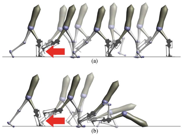
Here we extend the neuromuscular control approach to knee-ankle prostheses for transfemoral amputees. First, we review and modify a neuromuscular model of intact human locomotion to design a prosthesis controller based on muscle reflexes and local feedbacks (Sec. II). Next, to evaluate neuromuscular prosthesis control, we construct a simulation of an amputee walking on a powered prosthesis and perform optimizations to identify parameters that lead to robust locomotion over rough terrain (Sec. III). We then compare the performance of the proposed control to that of impedance control and find that the proposed control improves robustness to elevation changes and unexpected deviations from nominal walking, suggesting that it may help amputees prevent trips and falls (Fig. 1). Finally, we present preliminary results toward implementing the proposed control on a powered leg prosthesis currently under development. We investigate the resulting controller’s ability to reproduce the leg behavior of human gait in steady walking and probe the response of the prosthesis to impulse disturbances during swing (Sec. IV).
Fig. 1.
Snapshots following a simulated tripping event. Response of the proposed prosthetic control (A) and impedance control (B) to a 15 N ·s impulse applied shortly after toe-off (red arrow). The proposed neuromuscular model control successfully responds to the trip and continues walking. In contrast, impedance control cannot effectively react to the same disturbance and subsequently falls.
II. REFLEXIVE WALKING CONTROL
We propose a prosthesis control based on a neuromuscular model of unimpaired human locomotion similar to that presented in [14]. This work uses approximate models of muscle dynamics and hypothesized reflex pathways to generate joint torques for a seven-link planar biped, producing gaits that are kinetically, kinematically, and electromyographically similar to observed human locomotion patterns.
A drawback of the model presented in [14] is a lack of robust foot placement during swing, which is essential for balance recovery [15]–[17]. To address this issue, [18] analyzed the passive double-pendulum dynamics of a leg during swing and proposed a heuristic control that shapes these dynamics to achieve ground clearance and placement of the foot into target positions. Integrating this swing leg control with the previous muscle reflex control during stance allows the model to walk across terrain featuring unexpected steps with elevation changes in the range of −9 to +12 cm [19]. We adapt this hybrid neuromuscular model to derive a transfemoral prosthesis control.
A. Neuromuscular Stance Control
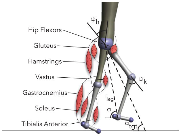
In stance, a leg of the hybrid model is actuated by seven Hill-type muscle tendon units [20] (soleus, gastrocnemius, tibialis anterior, vastus, hamstring, hip flexors, and gluteus) illustrated in Figure 2. These muscles produce torques about the ankle, knee and hip,
Fig. 2.
Unimpaired human walking model with labeled muscles and definitions of hip and knee angles, leg length, and current and target swing leg angles.
| (1) |
where rm(ϕi) is the variable moment arm of muscle m about joint i, and Fm(S, lmtc, lce) is the force produced by the muscle-tendon unit given stimulation S, muscle-tendon unit length lmtc, and contractile element length lce.
The muscles of the stance leg are stimulated by reflexes primarily in the form of muscle length and force feedbacks. In general, the stimulation Sm(t) of muscle m is modeled as
| (2) |
where is a constant pre-stimulation, is the time-delayed length or force signal from muscle n acting on muscle m, and is the gain on that signal. The reflexes encode several key functions of legged locomotion: generating compliant leg behavior, preventing knee overextension, and balancing the trunk.
The first function, generating compliant leg behavior, is achieved by positive force feedback reflexes on leg extensors: the soleus, vastus and gluteus. For example, the vastus is stimulated in part by
| (3) |
The second function, preventing knee overextension, is implemented via two mechanisms. The first mechanism is positive force feedback of biarticular muscles, the gastrocnemius and hamstrings, which helps counteract the tendency for knee overextension caused by ankle plantarflexion and hip extension torques, respectively. For example, the hamstring has a force feedback reflex,
| (4) |
which helps prevent both knee extension and hip flexion caused by heel-strike. A second mechanism further protects the knee by inhibiting the vastus stimulation in proportion to knee extension beyond a threshold, resulting in the complete vastus stimulation
| (5) |
where ϕoff is the angle beyond which the vastus is inhibited.
The final function of balancing the trunk is accomplished by a proportional-derivative control which produces stimulations for the hip muscles (hip flexors, gluteus, and hamstrings) to stabilize the trunk at a reference lean. Because muscles can only pull but not push, the proportional derivative control signal is distributed as hip flexor stimulation if the signal represents flexion torque and as simultaneous stimulation for the gluteus and hamstrings if it represents hip extension torque. For example, the complete hamstrings stimulation becomes
| (6) |
where the last two terms are the reflex contributions from the trunk balance control. A more detailed description of the stance reflex control can be found in [19].
B. Swing Leg Placement Control
The swing control comprises two layers. In the first layer, a leg placement policy
| (7) |
prescribes desired foot placement locations, where αtgt is the target leg angle, α0 is the default leg angle, d is the horizontal distance between the stance leg ankle and the model’s center of mass, v is the velocity of the center of mass, and cd and cv are constants. This policy is taken from [21] and presents an empirical generalization of the leg placement strategies that recover the linear inverted pendulum model of human walking from disturbances [16], [17].
The target angle generated by this policy forms a central input to the second layer, the swing limb control detailed in [18]. The portion of this control that governs the knee action uses a finite state machine to switch between three phases. The first phase allows the knee to passively flex in response to hip moments generated at the onset of swing. If the passive knee flexion is insufficient (the foot swings forward with a tendency to scuff the ground), the control produces active flexion torque of the knee in proportion to the rate α̇ of forward leg motion,
| (8) |
where ki is the flexion gain and the leg angle α is defined as the angle between the horizontal and the hip-ankle line.
The second phase activates when the leg length, defined as the distance between the hip and ankle, contracts below a threshold. In this phase, the knee torque is given by
| (9) |
where and are damping coefficients. The first case dampens knee flexion, while the second case dampens knee extension, but allows progressively more extension as the leg angle approaches its target. The modulation term (α̇ − ϕ̇k) prevents premature landing of the leg by damping the knee if it extends faster than the overall leg angle.
The third phase engages when the leg angle gets within a threshold of the target leg angle. The control then applies torque to stop and extend the knee,
| (10) |
where α̇max is the maximum leg retraction velocity for which the stopping knee torque is applied. When this torque brings the leg velocity to zero, a knee extension torque is added,
| (11) |
where l0 is the rest leg length, l is the current leg length, and kext is a proportional gain.
The swing leg control also specifies a hip torque in the form of a proportional derivative control on the leg angle,
| (12) |
This hip torque is supplemented by a feed forward term
| (13) |
that neutralizes the coupling dynamics between the knee and hip during the knee’s stop and extend phase (Eq. 10).
The torques produced by the swing controller augment the net torques produced by the Hill-type muscles and reflexes during stance. At heel strike, the control policy switches from using the swing leg control torques to the stance torques generated by the muscle models. In late stance, the policy mixes the torques specified by the stance and swing controllers by scaling the stance and swing torques and muscle stimulations in proportion to the normalized ground reaction force,
| (14) |
| (15) |
During swing, only the swing leg torques are used.
C. Reflex Prosthesis Design and Control
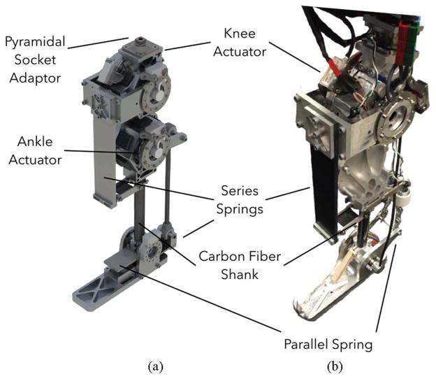
Balance recovery in humans can require peak torques and speeds at the knee joint of about 120 N ·m and 1.8 rev/s [22], [23]. Figure 3 shows a CAD rendering and an initial prototype of a powered knee-ankle prosthesis designed to achieve this performance envelope. The design includes two identical series elastic actuators (SEAs), each consisting of a brushless motor (TQ-Group ILM85-13HS), a Harmonic Drive gearset (CSG-25-50), and a series composite leaf spring. One actuator drives the knee joint and the other drives the ankle joint (Fig. 3a). Both are designed to produce peak joint speeds of about 1.67 rev/s, and peak joint torques of about 170 N ·m, assuming 75% gear efficiency. In addition, the ankle has a parallel spring that can store and release energy during the gait cycle. The design also includes two absolute encoders (Renishaw Resolute) per joint located on either side of each joint’s series elastic spring. These encoders measure the knee and ankle angles (θk and θa), and the deflection of the series springs, thereby providing an estimate of joint torques (τk and τa). Finally, the prosthesis also includes an IMU (YEI Technology 3-Space Sensor) mounted on the thigh side of the knee joint to estimate the thigh angle θt with respect to the vertical axis (Fig. 7). The complete prototype will weigh about 6 kg with an additional 5 kg carried in a backpack for batteries and motor controllers. Figure 3b shows our current development stage of the prototype with the powered knee joint and a passive ankle-foot.
Fig. 3.
Prosthesis prototype. (A) CAD render of proposed design of powered knee and ankle prosthesis used in simulated experiments. (B) Current stage of prototype with active knee and passive ankle used for hardware evaluation experiments.
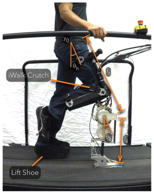
Fig. 7.
A non-amputee experimenter tests the prosthesis using an iWalk Crutch as a knee adaptor. The experimenter wears a lift shoe on the contralateral leg to compensate for the added thigh length of the prosthesis and knee adaptor.
The control of the prosthesis distinguishes between a lower level and a behavior level. At the lower level, each actuator is controlled by a SEA control [24], [25] that regulates a desired joint torque by commanding motor torque. The desired joint torques for the knee and ankle are generated at the behavior level by the control reviewed in sections II-A and II-B.
During stance, the behavior control simulates five virtual muscles that span the knee and ankle joints (Fig. 4; virtual soleus, gastrocnemius, tibialis anterior, vastus, and hamstring shown in blue). These muscles and their reflex controls realize the net torques at the knee and ankle joints required to generate compliant behavior and to prevent knee joint overextension (Sec. II-A). The virtual stimulations of these muscles require information about the knee and ankle angles of the prosthesis, which is provided by the joint position encoders. In addition, the biarticular hamstring stimulation requires knowledge of the amputee’s hip angle, which is estimated by the IMU mounted on the thigh (θh ≈ θt).
Fig. 4.
Control overview of the amputee walking model. The amputee and the prosthesis are driven by nearly identical neuromuscular controls. During stance, reflex stimulations of Hill-type muscles generate torques about the joints. During swing, the control specifies torques that drive the legs to desired landing angles αtgt (compare Fig. 2). To control the prosthesis, the torques produced by the muscles and the swing control are converted to motor voltages by series elastic actuator controllers.
During swing, the prosthesis uses the reviewed swing leg control to specify the knee torque (Sec. II-B). However, there is an important difference between the previously reviewed control and the control implemented on the prosthesis. As the prosthesis does not have access to information about the user’s center of mass and stance leg ankle position, we replace the adaptive leg placement policy (Eq. 7) with a constant target leg angle, αtgt = const. The prosthesis obtains information about the leg length and leg angle from the knee encoder and a thigh-mounted IMU using and α = π/2 − θh +arcsin ((ls sin θk)/l) respectively. In addition, during swing a length feedback reflex on a virtual tibialis anterior muscle dorsiflexes the ankle and improves foot ground clearance.
III. BALANCE RECOVERY IN SIMULATED EXPERIMENTS
A. Amputee Walking Simulation
We study the performance of the proposed transfemoral prosthesis controller in a simulation model of a unilateral amputee equipped with the proposed powered prosthesis. To more accurately model an amputee’s anatomy, we sever the femur of the unimpaired human model 11 cm above the knee and attach the hamstring muscle to the distal end of the shortened bone as recommended in [26]. This change converts the biarticular hamstring into a monoarticular muscle that only extends the hip. Next, we attach a model of the full prosthesis (Fig. 3A) to the severed femur (Fig. 4). The prosthesis model includes series elastic actuators for the knee and ankle, the electrical dynamics of the motors, gearbox ratios and resultant reflected inertias, and current-based SEA control for these actuators [24].
The reference torques for the SEAs are generated by the behavior control. The behavior control implements the hybrid neuromuscular control with one modification. Because the attachment of the hamstring muscle is relocated, the hip swing control on the prosthesis side does not have the feed-forward term neutralizing the disturbance created by the knee’s stop and extend phases (Eq. 13).
To compare the performance of the proposed control, we also simulate the state-of-the-art impedance control method at the behavior level [5]–[7], [11]. Specifically, we implement the impedance control presented in [6] as it tended to perform better than other versions in our simulations. This control partitions the gait cycle into four phases. In each phase i, the torque of an actuated joint is governed by an impedance function
| (16) |
where θ is the joint angle, θ1,i and θ2,i are angle offsets, and k1,i, k2,i and bi are the impedance parameters.
B. Controller Optimization for Natural and Robust Walking
For both the hybrid neuromuscular controller and the impedance controller, we use optimization to search for gaits that appear natural and are robust to disturbances. For the hybrid neuromuscular model, we optimize 53 parameters that include reflex feedback gains and swing leg control parameters for both the amputee and prosthesis as well as the SEA control gains. To reduce the number of parameters to optimize, we use fixed values for many parameters, such as the muscle properties and prestimulations. For the impedance controller, we optimize 59 parameters that include the reflex feedback gains and the swing leg control parameters for the amputee model, and the impedance parameters and SEA controller gains for the prosthesis. Again, to reduce the number of parameters to optimize, the impedance parameters that are set to zero according to [6] are fixed to zero during the optimization.
We rely on the covariance matrix adaptation evolution strategy (CMA-ES) [27] and perform optimization in two steps. In the first step, we search for control parameters that generate a gait with natural kinematics and kinetics. To this end, we take advantage of the observation that human gait seems to result from minimizing metabolic energy consumption [28], and use the cost of transport
| (17) |
as optimization criterion. In the cost, W accounts for the energy consumption of both the modeled amputee’s muscles and the prosthesis’ virtual muscles according to [29], τcmd is the sum of the torques commanded by the neuromuscular swing control or the impedance control, τlimit is the sum of torques produced by the model’s mechanical hardstops, which prevent knee and ankle hyperextension, m is the mass of the amputee, g is the gravitational acceleration, and x is the distance travelled in 20 seconds. The hand tuned constants, c1 = 0.1 and c2 = 0.01, ensure that the terms of the cost function have similar order-of-magnitude.
We run the above optimization for 300 iterations, and use the best resulting set of control parameters to seed an optimization for robustness to unexpected changes in ground height. For this second step, the cost function becomes
| (18) |
rewarding the distance travelled and penalizing joint hyperextension (c3 = 0.0005). Instead of level ground, we evaluate the cost using terrain that is flat for the first 10 meters (to allow the model to reach steady walking) and then features steps, spaced one meter apart and drawn from a uniform random distribution. The width of the distribution grows at a rate of 2.5 cm per meter distance travelled, resulting in steps that grow progressively rougher the farther the model walks. To avoid overfitting, we perform the evaluation on five different terrains, resulting in an average cost. Like in the first step, we stop the optimization after 300 iterations, resulting in the final, best set of control parameters.
C. Prosthesis Performance on Rough Terrain
We evaluate the performance of the proposed control and of impedance control by subjecting the amputee model to terrains that are flat for 10 meters and then feature steps drawn from uniform distributions for another 90 meters. The widths of the distributions are constant but vary among the terrains to test the control performance on steps of increasing steepness (0 cm to ±14 cm, 2cm increments, total of 8 terrains).
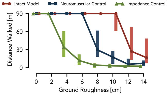
Figure 5 shows the distances the amputee model walks over 50 trials at each roughness level (proposed neuromuscular control in blue, impedance control in green). Most of the trials with the impedance-controlled prosthesis cover the full distance up to a roughness of 2 cm. At a roughness of 4 cm, however, the median distance drops to 34 m, which further declines as the roughness increases. In contrast, the prosthesis using the neuromuscular control, allows the amputee model to walk the full distance up to a roughness of 6 cm. Moreover, neuromuscular control has a similar distribution of distances walked at a roughness of 8 cm as impedance control has at a roughness of 4 cm.
Fig. 5.
Control performance of simulated prosthesis on rough terrain. The distances walked over terrains with different ground roughness are compared between the amputee model using a powered knee-ankle prosthesis with impedance control (green) and hybrid neuromuscular control (blue) as well as with the unimpaired human model (red). Shown are the median and range (25th and 75th percentiles) of the covered distances for 50 terrains sampled at each roughness level.
Although the prosthesis using neuromuscular control significantly improves the robustness of the amputee model on rough terrain, the performance trails by a large margin that of an unimpaired model (Fig. 5, red line), for which most of the trials covered the full distance up to a roughness of 10 cm. Limiting the swing leg placement targets in the neuromuscular prosthesis control to constant angles may account for some of this performance gap. In future work, we may overcome this limitation by estimating the amputee’s center of mass velocity and stance ankle position so that the prosthesis control can take advantage of the full leg placement policy (Eq. 7). Other sources for the performance gap could stem from differences in the inertial properties between the prosthesis and the healthy leg, delay and inaccuracy in the series elastic actuator torque tracking, and the increased number of parameters in the asymmetric amputee model, which can reduce the quality of the optimized solutions.
D. Prosthesis Response to Simulated Trips
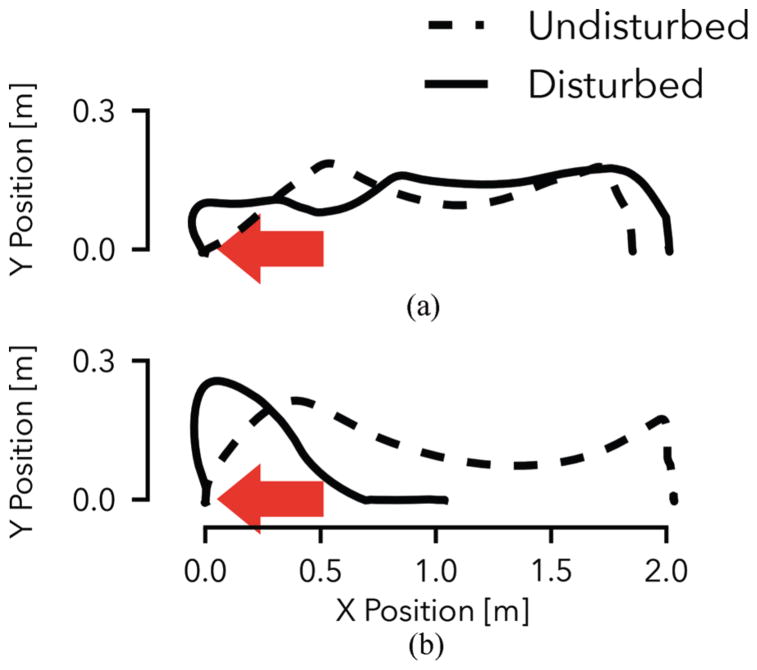
A possible explanation for why the neuromuscular control produces more robust behavior than impedance control is the former’s attempt to mimic the underlying dynamics and goals of human motor control rather than to track impedance behavior about a predefined motion for each individual joint. To illustrate this difference, we subject the amputee model with both control strategies to a simulated trip in the form of a 15 N ·s impulse applied at 5% of the undisturbed swing duration.
Figure 6A shows the toe trajectory of the prosthesis using neuromuscular control both in the undisturbed and disturbed cases. While the impulse causes a large deviation from the nominal trajectory in early swing, the controller quickly recovers. From mid-swing onward, the foot follows a qualitatively similar path, maintains adequate ground clearance, and successfully reaches a similar foot placement as in the undisturbed case. In contrast, the prosthesis with impedance control does not respond adequately when subjected to the disturbance (Fig. 6B). This is illustrated by the prosthesis behavior in mid swing, during which it does not react appropriately to maintain ground clearance of the toe. Rather, the joint-based impedance functions drive the knee into extension prematurely, and the prosthetic foot scuffs the ground resulting in a trip and subsequent fall (compare also Fig. 1).
Fig. 6.
Tripping response of the amputee model with neuromuscular (A) and impedance control (B) of the prosthesis. Shown are the prosthetic toe trajectories during undisturbed gait (dashed line) and when disturbed by a 15 N ·s impulse (solid line). The neuromuscular controller effectively responds to the disturbance and maintains a qualitatively similar toe trajectory. The impedance controller leads to foot scuffing and an eventual fall (compare Fig. 1).
IV. Initial Control Evaluation on Hardware
Our simulation results suggest that the proposed prosthesis design and control can improve balance recovery in transfemoral amputee walking in some situations. Towards a full realization and study on amputee subjects, we present a partial implementation and evaluation of the control on the current prosthesis prototype worn by a non-amputee user.
A. Experimental Testbed
Figure 7 shows an able-bodied user wearing our current prosthesis prototype. The current prosthesis prototype has an active knee SEA unit and an unpowered, spring-loaded, ankle (compare Fig. 3B). We connect the prosthesis to a knee crutch (iWalk 2.0 Hands Free Crutch) in order to allow a non-amputee experimenter to test the control. Additionally, the experimenter wears a lift shoe to compensate for the added thigh length of the knee crutch and prosthesis.
To control the prosthesis knee, we use Simulink Real-Time (Mathworks, USA), which samples all sensors (joint encoders, IMU on thigh, force sensors in foot), runs a low level SEA control [25], and sends commands to the motor controller at a rate of 1 kHz (compare Sec. II-C). In addition, the realtime software executes the hybrid neuromuscular behavior control at a rate of 5 kHz, ensuring that the integration (ode1) of the simulated muscle dynamics remains stable.
The behavior control of the knee is identical in swing to the one used in the simulation experiments (Eqs. 8–11); however, the missing ankle actuation in the current prosthesis prototype restricts the neuromuscular stance control to those muscles that span the knee: the vastus, hamstring, and gastrocnemius. The hamstring and vastus are stimulated according to equations 4 and 5 respectively. Similarly, the gastrocnemius is stimulated by positive force feedback (compare Sec. II-A). (The torso balance contribution of the complete hamstring stimulation, Eq. 6, is neglected.)
B. Slow Walking Behavior
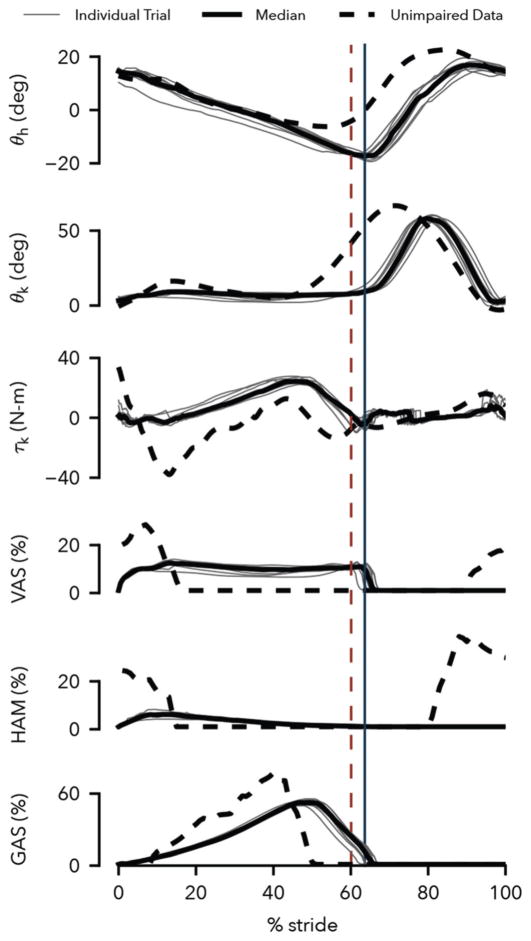
We first test if the prosthesis control can reproduce normal stance and swing behavior of the lower limb in steady-state walking. For this purpose, we capture joint kinematics and kinetics as well as the virtual muscle activations of the prosthesis control while an experimenter walks for ten trials with the crutch and prosthesis system on a treadmill. Because the fit of the crutch to the experimenter’s leg is not very tight, we limit the walking speed to 0.5 m/s and the experimenter holds onto handrails for safety (Figure 7).
The control generates steady-state prosthesis behavior that qualitatively reproduces human leg behavior in walking. Figure 8 compares the observed prosthesis leg behavior (solid lines) to corresponding human data at the preferred walking speed (dashed lines, adapted from [30], [31]). The hip and knee kinematics match overall, although later transitions from stance to swing are observed in both joints (θh and θk) and the prosthesis knee flexes less in stance (θk). The knee torque follows trends similar to human data, but the peak flexion and extension torques in the early stance phase are diminished (τk). These lower peaks are caused by reduced activations of the virtual vastus and hamstring muscles (VAS and HAM) in this phase, a clear difference to these muscles’ activations in humans, in which bursts of activity at heel strike are followed by relative silence. Finally, the activity of the virtual gastrocnemius muscle (GAS) bears strong similarity to the activity of this muscle in human walking.
Fig. 8.
Prosthesis behavior at walking speed of 0.5 m/s. Shown are the hip and knee trajectories, the knee controller torque, and the activations of the vastus, hamstring, and gastrocnemius muscles generated by the prosthesis control in the testbed. Solid black lines show averaged data of ten trials with the individual trials depicted in gray. Dashed lines show corresponding data from human walking at preferred speed (joint angles and knee torque: [30], muscle surface electromyograms: [31]). Solid and dashed vertical lines indicate median toe off times for the prosthesis and human data respectively.
To some extent, limitations of our current experimental testbed may account for observed discrepancies. The imposed slow walking speed of 0.5 m/s required less energy absorption in early stance than a normal walking speed. Moreover, the experimenter held onto the handrails to assist with lateral balance, which may have channeled some impact energy through the arms. In addition, the hybrid nature of the proposed control prevents the virtual muscles from activating in swing, which is the case in humans (Fig. 8, VAS and HAM activities from 80% to 100% of gait cycle), and would alter the response of the virtual muscles at heel strike. Finally, the lack of an active ankle and its control in the current prosthesis prototype further limits how closely the leg behaviors can match.
C. Response to Swing Leg Tripping
In a second set of experiments, we evaluate the response of the prosthesis controller to trip disturbances. We apply disturbances during treadmill walking by commanding flexion knee torques to the prosthesis in addition to its swing-leg control torque. The added torque simulates an obstacle encounter modeled in the same way as the stopping torque of the swing leg control (Eq. 10), with αthr replaced by a disturbance leg angle. The foot can pass the simulated obstacle if the leg length contracts beyond a threshold of 94 cm. For an early-, mid-, or late-swing encounter, the disturbance angle is set to 110, 95, or 80 degrees, respectively. In addition, anticipation of the trip by the experimenter is prevented by applying the disturbance only with a probability of 25%.
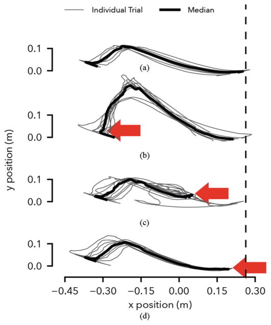
The experiments reveal that in response to disturbances during early and late swing, the prosthesis control places the swing leg with high repeatability and produces leg elevating and lowering strategies observed in humans. Figure 9 shows the Cartesian ankle trajectory in swing over 10 trials for the undisturbed (A) and disturbed conditions (B-D). In the undisturbed condition, the leg placement is repeatable with an interquartile range (IQR) of landing positions of 3.1 cm and a bias of 2.7 cm (median) from the target (dashed line). (Further tuning of the control parameters should improve the landing position accuracy.)
Fig. 9.
Response to simulated tripping disturbance. (A) Undisturbed ankle trajectory calculated from hip and knee angles assuming constant hip height. (B-D) Ankle trajectories with disturbance applied in early, mid and late swing (arrows). The vertical dashed line shows the target landing position of the foot, which corresponds to a 75 degree landing angle.
In the early disturbance condition (Fig. 9B), the prosthesis generates large knee flexion roughly doubling the peak ground clearance. Nonetheless, the median landing position remains within 5.3 cm of the target (IQR: 10.2 cm), demonstrating the knee control’s ability to compensate for early swing disturbances. This response is similar to the leg elevating strategy observed in humans when disturbed shortly after toe-off [32], [33]. The biological strategy, however, shows active knee flexor muscle contributions, while the prosthesis knee flexion is entirely passive, as the leg angular velocity does not become negative during the disturbance (Eq. 8, Sec. II-B).
In the late disturbance condition (Fig. 9D), the prosthesis leg behavior resembles the lowering strategy of humans [33], in which knee extensor muscles quickly extend the leg. This behavior is triggered on the prosthesis in the third phase of the swing control before the leg angle starts to retract (Eq. 11). The prosthesis achieves ground contact slightly earlier with a median landing point of 8.8 cm before the target (IQR: 3 cm).
Finally, Figure 9C shows the response of the prosthesis to a mid-swing disturbance. When humans are confronted with disturbances in mid swing, they may use either elevating or lowering strategies [32], [33]. However, the prosthesis response resembles neither strategy. During mid swing, the prosthesis control uses a holding policy, damping both knee flexion and extension (Eq. 9). Consequently, in most cases the knee angle neither flexes adequately to clear the obstacle nor extends quickly enough to make timely ground contact. In these trials, falling was only prevented via support from the treadmill handrails.
V. Discussion
Our simulation results suggest that the hybrid neuromuscular control policy can improve amputee gait stability over existing impedance control methods. An amputee model walking with a powered prosthesis showed substantial improvements in balance recovery on rough ground and after swing leg trips when using the hybrid neuromuscular control policy as opposed to impedance control. One possible reason for the improvement is that the proposed controller considers global leg information such as the target leg angle (Eqs. 8–10), and it is well known that without placing the feet into proper target points on the ground, legged systems fail to balance [15]–[17], [34]–[36]. A second reason could be that the design of the swing leg control policy explicitly accounts for large disturbances to the lower limb dynamics in order to achieve desired leg placements [18]. Neither is the case for current impedance control policies; however, future research may show that impedance or other control policies can equally make use of this global information and design criterion.
Whether the simulation results transfer to amputee gait remains to be determined. In an initial test with a non-amputee experimenter wearing the prosthesis via a knee adaptor, we found the hybrid neuromuscular control reproduces normal walking patterns qualitatively and effectively responds to disturbances in early and late swing. To understand if these initial results generalize to amputee locomotion requires further research. First, we only simulated disturbances in the hardware tests by commanding disturbance torques to the prosthesis knee. This approach allowed us to apply reproducible disturbances, but it does not capture real tripping or obstacle encounters, which will, for instance, exert torques about the hip joint as well. Second, the use of the knee adaptor creates abnormal kinematics and inertias and provides only a loose fit between user and prosthesis. In consequence, we only tested slow walking at 0.5 m/s holding onto hand rails.
Finally, the simulation and hardware tests captured only a small portion of the balance disturbances that humans typically encounter [37]. Other disturbances may evoke amputee responses that the simulation model does not capture; especially since it is driven solely by a reflexive walking controller that ignores conscious interventions. Already, the hardware experiments revealed that the control’s response to mid-swing disturbances does not match observed human responses and risks allowing the user to fall. This result suggests the model and corresponding hardware implementation require additional reflexes or structural changes in the control to better capture human locomotion and balance recovery. Foot placement into target points, while beneficial in particular for responding to early swing disturbances and for rough ground walking, may not be a goal that the human system prioritizes in response to other disturbances. Identifying human objectives in these situations could lead to improved leg prosthesis behaviors independent of the proposed approach, impedance-like approaches, or other control design approaches.
VI. CONCLUSION
We extended a neuromuscular model to formulate a control policy for powered knee-ankle prostheses. The proposed control approach differs from existing methods like impedance control as it incorporates high-level goals such as the target leg angle, which may help improve amputee gait stability and stumble recovery.
We evaluated the proposed control in simulation experiments with an amputee gait model and presented preliminary results captured from a non-amputee experimenter wearing a prototype of a powered leg prosthesis with a knee-adaptor. Our simulation results suggest that the proposed control enables an amputee to walk over rougher terrain and recover from larger disturbances than an amputee walking with an otherwise identical impedance controlled prosthesis. Our results from the initial hardware implementation of the proposed control indicate that it qualitatively reproduces human leg behavior of steady walking and shows biological responses to disturbances to the swing leg during early and late swing. However, evaluating if these results truly lead to improved balance recovery as performed by amputees will require more experiments. In addition, improving the control’s response to mid-swing disturbances and investigating how well it extends to other types of balance disturbances that humans typically encounter will require further research.
Acknowledgments
This work is supported in part by the Eunice Kennedy Shriver National Institute of Child Health & Human Development (award no. 1R01HD075492) and by the National Science Foundation Graduate Research Fellowship (grant no. 0946825).
Contributor Information
Nitish Thatte, The Robotics Institute, Carnegie Mellon University, 5000 Forbes Ave, Pittsburgh, PA 15213.
Hartmut Geyer, The Robotics Institute, Carnegie Mellon University, 5000 Forbes Ave, Pittsburgh, PA 15213.
References
- 1.Ziegler-Graham K, MacKenzie EJ, Ephraim PL, Travison TG, Brookmeyer R. Estimating the prevalence of limb loss in the united states: 2005 to 2050. Archives of physical medicine and rehabilitation. 2008;89(3):422–429. doi: 10.1016/j.apmr.2007.11.005. [DOI] [PubMed] [Google Scholar]
- 2.Pasquina PF, Bryant PR, Huang ME, Roberts TL, Nelson VS, Flood KM. Advances in amputee care. Archives of Physical Medicine and Rehabilitation. 2006;87(3 Supplement):34–43. doi: 10.1016/j.apmr.2005.11.026. [DOI] [PubMed] [Google Scholar]
- 3.Waters R, Perry J, Antonelli D, Hislop H. Energy cost of walking of amputees: the influence of level of amputation. J Bone Joint Surg Am. 1976;58(1):42–46. [PubMed] [Google Scholar]
- 4.Bellmann M, Schmalz T, Blumentritt S. Comparative biomechanical analysis of current microprocessor-controlled prosthetic knee joints. Archives of physical medicine and rehabilitation. 2010;91(4):644–652. doi: 10.1016/j.apmr.2009.12.014. [DOI] [PubMed] [Google Scholar]
- 5.Sup F, Bohara A, Goldfarb M. Design and control of a powered knee and ankle prosthesis,” in. Robotics and Automation, 2007 IEEE International Conference on. 2007:4134–4139. [Google Scholar]
- 6.Sup F, Bohara A, Goldfarb M. Design and control of a powered transfemoral prosthesis. The International Journal of Robotics Research. 2008;27(2):263–273. doi: 10.1177/0278364907084588. [DOI] [PMC free article] [PubMed] [Google Scholar]
- 7.Sup F, Varol HA, Mitchell J, Withrow TJ, Goldfarb M. Preliminary evaluations of a self-contained anthropomorphic transfemoral prosthesis. Mechatronics, IEEE/ASME Transactions on. 2009;14(6):667–676. doi: 10.1109/TMECH.2009.2032688. [DOI] [PMC free article] [PubMed] [Google Scholar]
- 8.Lenzi T, Hargrove L, Sensinger J. Speed-adaptation mechanism: Robotic prostheses can actively regulate joint torque. Robotics & Automation Magazine IEEE. 2014;21(4):94–107. [Google Scholar]
- 9.Lenzi T, Hargrove L, Sensinger J. Minimum jerk swing control allows variable cadence in powered transfemoral prostheses. Conference proceedings:... Annual International Conference of the IEEE Engineering in Medicine and Biology Society. IEEE Engineering in Medicine and Biology Society. Annual Conference; 2014; 2014. pp. 2492–2495. [DOI] [PubMed] [Google Scholar]
- 10.Gregg RD, Lenzi T, Hargrove LJ, Sensinger JW. Virtual constraint control of a powered prosthetic leg: From simulation to experiments with transfemoral amputees. Robotics IEEE Transactions on. 2014;30(6):1455–1471. doi: 10.1109/TRO.2014.2361937. [DOI] [PMC free article] [PubMed] [Google Scholar]
- 11.Sup F, Varol HA, Goldfarb M. Upslope walking with a powered knee and ankle prosthesis: initial results with an amputee subject. Neural Systems and Rehabilitation Engineering IEEE Transactions on. 2011;19(1):71–78. doi: 10.1109/TNSRE.2010.2087360. [DOI] [PubMed] [Google Scholar]
- 12.Lawson BE, Varol HA, Sup F, Goldfarb M. Stumble detection and classification for an intelligent transfemoral prosthesis. Engineering in Medicine and Biology Society (EMBC), 2010 Annual International Conference of the IEEE; IEEE; 2010. pp. 511–514. [DOI] [PubMed] [Google Scholar]
- 13.Eilenberg MF, Geyer H, Herr H. Control of a powered ankle–foot prosthesis based on a neuromuscular model. Neural Systems and Rehabilitation Engineering IEEE Transactions on. 2010;18(2):164–173. doi: 10.1109/TNSRE.2009.2039620. [DOI] [PubMed] [Google Scholar]
- 14.Geyer H, Herr H. A muscle-reflex model that encodes principles of legged mechanics produces human walking dynamics and muscle activities. Neural Systems and Rehabilitation Engineering IEEE Transactions on. 2010;18(3):263–273. doi: 10.1109/TNSRE.2010.2047592. [DOI] [PubMed] [Google Scholar]
- 15.Raibert MH. Legged robots that balance. MIT press; Cambridge: 1986. [Google Scholar]
- 16.Kajita S, Kanehiro F, Kaneko K, Yokoi K, Hirukawa H. The 3D linear inverted pendulum mode: a simple modeling for a biped walking pattern generation. Proceedings. 2001 IEEE/RSJ International Conference on Intelligent Robots and Systems; 2001. pp. 239–246. [Google Scholar]
- 17.Pratt J, Carff J, Drakunov S, Goswami A. Capture Point: A Step toward Humanoid Push Recovery. Proceedings of the 6th IEEE-RAS Intl Conf on Humanoid Robots; 2006. [Google Scholar]
- 18.Desai R, Geyer H. Robust swing leg placement under large disturbances. Robotics and Biomimetics (ROBIO), 2012 IEEE International Conference on; 2012. pp. 265–270. [Google Scholar]
- 19.Song S, Desai R, Geyer H. Integration of an adaptive swing control into a neuromuscular human walking model. Engineering in Medicine and Biology Society (EMBC), 2013 35th Annual International Conference of the IEEE; 2013. pp. 4915–4918. [DOI] [PubMed] [Google Scholar]
- 20.van Leeuwen JL. Muscle function in locomotion. In: Alexander R, editor. Mechanics of animal locomotion. Vol. 11. Springer-Verlag; New York: 1992. pp. 191–249. [Google Scholar]
- 21.Yin K, Loken K, van de Panne M. ACM Transactions on Graphics (TOG) 3. Vol. 26. ACM; 2007. Simbicon: Simple biped locomotion control; p. 105. [Google Scholar]
- 22.Madigan ML, Lloyd EM. Age-related differences in peak joint torques during the support phase of single-step recovery from a forward fall. The Journals of Gerontology Series A: Biological Sciences and Medical Sciences. 2005;60(7):910–914. doi: 10.1093/gerona/60.7.910. [DOI] [PubMed] [Google Scholar]
- 23.Grabiner MD, Koh TJ, Lundin TM, Jahnigen DW. Kinematics of recovery from a stumble. Journal of gerontology. 1993;48(3):M97–M102. doi: 10.1093/geronj/48.3.m97. [DOI] [PubMed] [Google Scholar]
- 24.Pratt G, Williamson M. Series elastic actuators. Intelligent Robots and Systems 95. ’Human Robot Interaction and Cooperative Robots’, Proceedings. 1995 IEEE/RSJ International Conference on; 1995. pp. 399–406. [Google Scholar]
- 25.Schepelmann A, Taylor MD, Geyer H. Development of a Testbed for Robotic Neuromuscular Controllers. Robotics: Science and Systems VIII - Online Proceedings. 2012 [Online]. Available: http://www.roboticsproceedings.org/rss08/p49.html.
- 26.Brown BJ, Crone CG, Attinger CE. Seminars in Vascular Surgery. 2. Vol. 25. Elsevier; 2012. Amputation in the diabetic to maximize function; pp. 115–121. [DOI] [PubMed] [Google Scholar]
- 27.Hansen N. The cma evolution strategy: A comparing review. In: Lozano J, Larraaga P, Inza I, Bengoetxea E, editors. Towards a New Evolutionary Computation. Vol. 192. Springer; Berlin Heidelberg: 2006. pp. 75–102. ser. Studies in Fuzziness and Soft Computing. [Google Scholar]
- 28.McNeill Alexander R. Energetics and optimization of human walking and running: the 2000 raymond pearl memorial lecture. American Journal of Human Biology. 2002;14(5):641–648. doi: 10.1002/ajhb.10067. [DOI] [PubMed] [Google Scholar]
- 29.Umberger BR, Gerritsen KG, Martin PE. A model of human muscle energy expenditure. Computer methods in biomechanics and biomedical engineering. 2003;6(2):99–111. doi: 10.1080/1025584031000091678. [DOI] [PubMed] [Google Scholar]
- 30.Winter DA. Biomechanics and motor control of human movement. John Wiley & Sons; 2009. [Google Scholar]
- 31.Perry J, Burnfield J. Gait Analysis: Normal and Pathological Function. SLACK. 2010 [Online]. Available: https://books.google.com/books?id=DICTQAAACAAJ.
- 32.Eng JJ, Winter DA, Patla AE. Strategies for recovery from a trip in early and late swing during human walking. Experimental Brain Research. 1994;102(2):339–349. doi: 10.1007/BF00227520. [DOI] [PubMed] [Google Scholar]
- 33.Schillings A, Van Wezel B, Mulder T, Duysens J. Muscular responses and movement strategies during stumbling over obstacles. Journal of Neurophysiology. 2000;83(4):2093–2102. doi: 10.1152/jn.2000.83.4.2093. [DOI] [PubMed] [Google Scholar]
- 34.Townsend MA. Biped gait stabilization via foot placement. J Biomech. 1985;18(1):21–38. doi: 10.1016/0021-9290(85)90042-9. [DOI] [PubMed] [Google Scholar]
- 35.Seyfarth A, Geyer H, Günther M, Blickhan R. A movement criterion for running. J of Biomech. 2002;35:649–655. doi: 10.1016/s0021-9290(01)00245-7. [DOI] [PubMed] [Google Scholar]
- 36.Wu A, Geyer H. The 3-D Spring-Mass Model Reveals a Time-Based Deadbeat Control for Highly Robust Running and Steering in Uncertain Environments. IEEE Transactions on Robotics. 2013;29(5):1114–1124. [Google Scholar]
- 37.Robinovitch SN, Feldman F, Yang Y, Schonnop R, Leung PM, Sarraf T, Sims-Gould J, Loughin M. Video capture of the circumstances of falls in elderly people residing in long-term care: an observational study. The Lancet. 2013;381(9860):47–54. doi: 10.1016/S0140-6736(12)61263-X. [DOI] [PMC free article] [PubMed] [Google Scholar]


