Abstract
Spin-Cherenkov effect enables strong excitations of spin waves (SWs) with nonlinear wave dispersions. The Dzyaloshinskii-Moriya interaction (DMI) results in anisotropy and nonreciprocity of SWs propagation. In this work, we study the effect of the interfacial DMI on SW Cherenkov excitations in permalloy thin-film strips within the framework of micromagnetism. By performing micromagnetic simulations, it is shown that coherent SWs are excited when the velocity of a moving magnetic source exceeds the propagation velocity of the SWs. Moreover, the threshold velocity of the moving magnetic source with finite DMI can be reduced compared to the case of zero DMI. It thereby provides a promising route towards efficient spin wave generation and propagation, with potential applications in spintronic and magnonic devices.
The Cherenkov radiation of light1 occurs when a charged particle moves faster than the light speed within a medium. This effect is named after Pavel Alekseyevich Cherenkov, who studied this phenomenon experimentally. Cherenkov radiation is used frequently in particle identification detectors in particle physics2. The Cherenkov effect is analogous to the sonic boom produced by shock waves propagating away from an aircraft, if its speed exceeds the sound velocity. Similar to the Doppler effect observed in different physical system3,4,5,6,7, the Cherenkov effect belongs to one of the fundamental phenomena induced by the radiation of moving sources. The Cherenkov-like effect of SWs has been theoretically studied in ferromagnets, which can be used to excite coherent SWs without the necessity of external alternating magnetic field or current8,9. Recently, the study of the influence of the antisymmetric exchange interaction, namely the Dzyaloshinskii-Moriya interaction (DMI), on magnetic excitations such as domain walls and vortex is one of the hottest topics in nanomagnetism and spintronics10,11,12,13,14,15,16,17,18,19,20. DMI is an antisymmetric interaction induced by spin-orbital coupling due to broken inversion symmetry in lattices or at the interface of magnetic films12, which has been measured for both magnetic interfaces21,22 and bulk materials23,24. DMI facilitates the creation of topologically protected spin textures in chiral magnetic materials, i.e. magnetic skyrmions, which are favorable information carriers in the next-generation data storage and spin logic devices. On the other hand, theoretical13,14,16 and experimental10,15,25 studies have demonstrated that DMI leads to an asymmetrical spin-wave dispersion. DMI has also been measured in a wide range of materials including permalloy22,26,27. Specifically, the asymmetry in the formation of a vortex state in a permalloy nanodisk has been studied by micromagnetic simulations with interfacial DMI22.
In this paper, the influence of interfacial DMI on the Spin-Cherenkov effect (SCE) in permalloy strip are studied by micromagnetic simulations. Pictorial illustrations of the setup is shown in Fig. 1, where a rectangular moving magnetic field pulse is applied to the permalloy strip with a magnitude of 10 mT along the +z-direction. Our numerical results show that the interfacial DMI leads to a reduction of the threshold velocity of moving source, i.e. the minimum SW phase velocity, for coherent SW excitation in the absence of external ac magnetic field. Therefore it provides a promising route to reducing SCE threshold to facilitate experimental realization of such effect in magnetic medium.
Figure 1. Schematics of the micromagnetically modeled system.
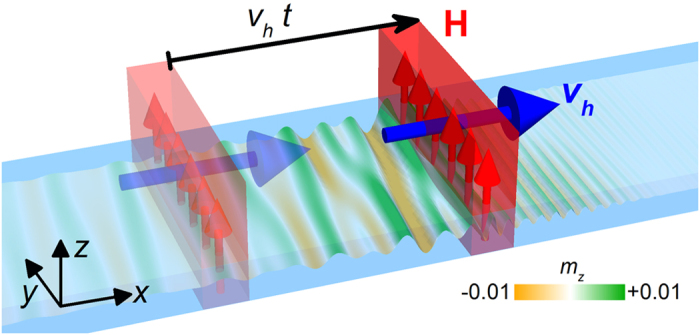
An external rectangular shape field pulse (H), 12 nm wide in the x-direction and 100 nm long in the y-direction, is applied to a 12-μm-long, 100-nm-wide, and 10-nm-thick magnetic strip with a magnitude of 10 mT in the z-direction and constant speed of vh. The color scale represents the out-of-plane component of the magnetization mz, which has been used throughout this paper.
Results
SW excitation via SCE in permalloy strips
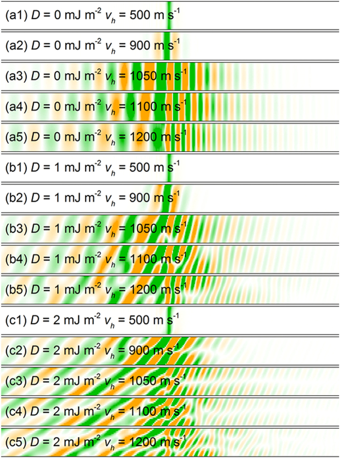
The response of the magnetization distribution to the pulse velocity vh is shown in Fig. 2. A localized magnetic field of constant magnitude traveling along the wire axial direction with velocity of vh, is applied to mimic the interacting force with the magnetization. The magnetization dynamics is strongly dependent on the pulse velocity vh. For D = 0 mJ m−2 and vh = 500 m s−1 and 900 m s−1 (see Fig. 2(a1), the moving magnetic field pulse only causes a distortion of the magnetization distribution traveling with the pulse. There is no spin wave (SW) excitation by the moving pulse. As the velocity of the magnetic pulse increases, SW excitations are observed for vh = 1050 m s−1, 1100 m s−1 and 1200 m s−1, as shown in Fig. 2(a3–a5). At vh = 1050 m s−1, the SWs proceeding the source and lagging the source are well-distinguished with different wave lengths. Upon the application of a moving dc magnetic field pulse, the system reaches a dynamic equilibrium and the excited spin waves comprise of two branches, giving rise to the SCE as reported in Ref. 9.
Figure 2. Snapshots of the z-component of the magnetization in a magnetic strip in the vicinity of the field pulse traveling at a constant speed.
(a1) D = 0 mJ m−2 and vh = 500 m s−1, (a2) D = 0 mJ m−2 and vh = 900 m s−1, (a3) D = 0 mJ m−2 and vh = 1050 m s−1, (a4) D = 0 mJ m−2 and vh = 1100 m s−1, (a5) D = 0 mJ m−2 and vh = 1200 m s−1, (b1) D = 1 mJ m−2 and vh = 500 m s−1, (b2) D = 1 mJ m−2 and vh = 900 m s−1, (b3) D = 1 mJ m−2 and vh = 1050 m s−1, (b4) D = 1 mJ m−2 and vh = 1100 m s−1, (b5) D = 1 mJ m−2 and vh = 1200 m s−1, (c1) D = 2 mJ m−2 and vh = 500 m s−1, (c2) D = 2 mJ m−2 and vh = 900 m s−1, (c3) D = 2 mJ m−2 and vh = 1050 m s−1, (c4) D = 2 mJ m−2 and vh = 1100 m s−1, (c5) D = 2 mJ m−2 and vh = 1200 m s−1.
For the permalloy nanostrip with interfacial DMI, similar magnetization dynamics occur as the moving field pulse is applied. For the case of D = 1 mJ m−2, there is no SW excitation by the moving magnetic field with the speed of vh = 500 m s−1 and 900 m s−1. The Cherenkov emission of SWs emerge at vh = 1050 m s−1, 1100 m s−1 and 1200 m s−1 in the permalloy strip as shown in Fig. 2(b3–b5). The SWs excited in permalloy nanostrip are distorted due to the presence of DMI. The interfacial DMI term for any in-plane direction u can be expressed as Dz × u28, which may be treated as an effective field transverse to the magnetic track, resulting in the distorted spin waves. As D = 2 mJ m−2, spin wave is excited when vh = 900 m s−1, indicating that the presence of interfacial DMI leads to the decreasing of the threshold velocity of the moving field source for spin wave excitation. It should be noticed that the SWs with more significant distortions are observed at vh = 1050 m s−1, 1100 m s−1 and 1200 m s−1 as shown in Fig. 2(c3–c5). Moreover, the difference between the SW branches proceeding and lagging the source becomes even more obvious with increasing DMI strength for a given pulse velocity.
Figure 3 shows the numerically determined SW phase velocity vp(k) and group velocity vg(k) for D = 0 mJ m−2. The inset of Fig. 3 shows the SW dispersion in the permalloy strip, which agrees well with the analytical results for zero DMI (proportional to k2). In Fig. 3, the phase velocity vp and vg of the SWs are extracted from the dispersion relation of vp(k) = ω/k and vg(k) = dω/dk. The minimum of the phase velocity occurs around 1000 m s−1, meaning that no SW is excited by the moving field pulse in the permalloy strip for the pulse velocities below the minimum v0. In other words, the velocity v0 is the threshold velocity of SCE, below which there is no coherent SWs excitation. As the field pulse moves at a velocity larger than v0, there are two SW modes excited with different group velocity vg but equal phase velocity vp. The SW packet with larger  (vg > vp) moves in the front of the source and leaves the one with smaller
  (vg < vp) behind. The field pulses with different velocity vh are applied and the corresponding responses of the magnetization distribution are shown in Fig. 2(a1–a5). The calculated k are shown with color stars in Fig. 3. As vh is below the critical velocity, there is no SW excitation by the moving field pulse. When vh = 1050 m s−1, there are two SW modes observed in the permalloy strip. The spin waves formed in front of and behind the pulse exhibit different characteristics in Fig. 2(a3), and the corresponding k values are shown in Fig. 3. The Cherenkov emission of SWs can also be observed for the case of vh = 1100 m s−1 and 1200 m s−1. The dispersions are in an excellent agreement with the curves of vp(k) and vg(k). The curves of vp(k) and vg(k) extracted from the numerical SW dispersion relation ω(k), which is obtained by applying a localized ac field and extracting the wavelength of the excited spin waves, can predict the Cherenkov excitation of SWs precisely.
Figure 3. Numerically determined phase velocity vp(k) and group velocity vg(k) of SWs in the magnetic strip which is 12 μm long, 100 nm wide, and 10 nm thick as D = 0 mJ m−2.
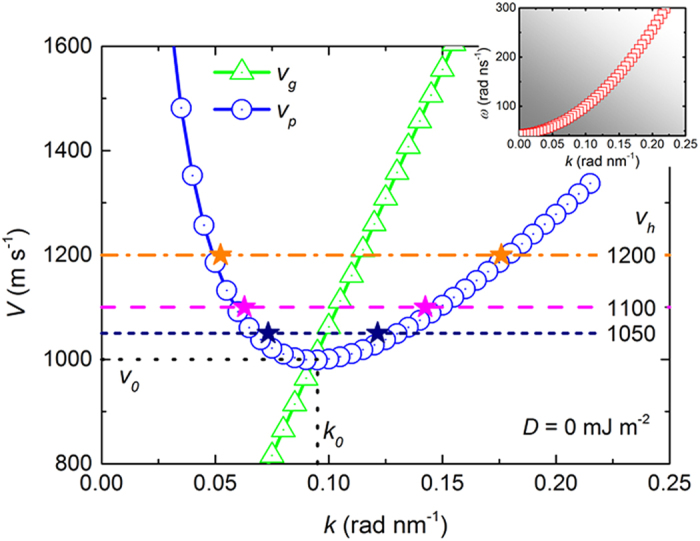
The value of vp(k) and vg(k) are extracted from the SW dispersion relation ω(k) shown in the inset. vp(k) has a minimum v0 at k0, where the two curves vp(k) and vg(k) cross. The colored stars represent the wave vectors of the SW tails excited by the moving field pulse applied to the strip at the corresponding speed. The colored horizontal line, indicating the speed of the field pulse, connect the two SW branches.
Influence of DMI on SCE in permalloy
Figure 4 shows the numerically determined phase velocity vp(k) and group velocity vg(k) with D = 2 mJ m−2, where vp(k) and vg(k) are calculated from the SW dispersion relation ω(k) shown in the inset. Similar to the case of D = 0 mJ m−2, there exists a critical velocity v0 for the Cherenkov excitation of SWs. The Cherenkov excitation of SWs can be observed for vh > v0 (887 m s−1). We also investigate the evolution of the SW branches by varying vh for D = 2 mJ m−2. At vh = 1050 m s−1, the Cherenkov excitation of SWs is observed with two SW modes formed in the permalloy strip. The calculated k marked with color stars agrees very well with the numerically determined curve of vp(k). The curves of vp(k) and vg(k) extracted from the SW dispersion relation ω(k) can predict the Cherenkov excitation of SWs precisely with the presence of finite DMI.
Figure 4. Numerically determined phase velocity vp(k) and group velocity vg(k) of SWs in the magnetic strip, with a length of 12 μm, a width of 100 nm, and a thickness of 10 nm when D = 2 mJ m−2.
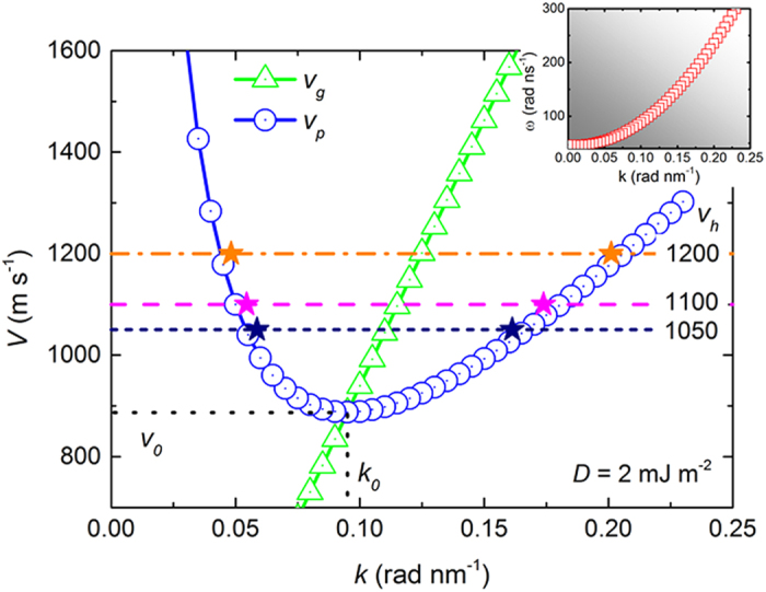
The value of vp(k) and vg(k) are extracted from the SW dispersion relation ω(k) shown in the inset. vp(k) has a minimum v0 at k0, where the curve vp(k) crosses the curve vg(k). The colored stars show the wave vectors of the SW tails excited by the moving field pulse applied to the strip at the corresponding speed. The colored horizontal line, indicating the speed of the field pulse, connects the two SW branches.
Figure 5 shows the minimum velocity v0 of the Spin-Cherenkov excitation for D = 0 mJ m−2, 1 mJ m−2, 2 mJ m−2 and 3 mJ m−2, as well as the corresponding dispersion relation. Only the branches of positive k are shown. The critical velocity for the SCE decreases linearly with increasing DMI in the investigated DMI range. As shown in the inset of Fig. 5, the dispersion relation for D = 1 mJ m−2 deviates from the case of D = 0 mJ m−2, resulting in a smaller critical velocity v0. v0 = 1000 m s−1 for D = 0 mJ m−2 whereas v0 = 944 m s−1 for D = 1 mJ m−2. The critical velocity further drops to 887 m s−1 as D increases to 2 mJ m−2, indicating that the Cherenkov emission of SWs in permalloy strip with finite DMI can be excited more easily than the case of zero DMI. The SW dispersion relations without DMI (D = 0 mJ m−2) is a parabolic function of SW vector k when k is large9,13,29,30. In Refs. 14 and 25, the SW dispersion relation is given analytically when DMI is included, indicating that the interfacial DMI results in the asymmetric dispersion. Such asymmetric dependence due to the interfacial DMI depends on the spin wave vector k and equilibrium magnetization distributions. Different with the typical Damon-Eshbach spin waves studied in Refs. 14 and 25, the SWs in our case propagate along the ±x-directions while the equilibrium magnetization is along the +x-direction, corresponding to the back-volume mode. The SW dispersion is given by  when the DMI is considered. Here
  and ω0 is the angular frequency in the absence of DMI. mz0 is the z-component of the magnetization. The SW dispersion relation remains symmetric, when the interfacial DMI is included. The SCE threshold can be calculated by
  , which decreases with DMI9.
Figure 5. The minimum velocity v0 for the Spin-Cherenkov excitation as D = 0 mJ m−2, 1 mJ m−2, 2 mJ m−2 and 3 mJ m−2.
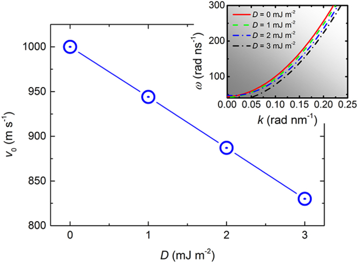
The insets shows the corresponding dispersion relations, which are obtained by applying a localized ac magnetic field and extracting the wavelength of the excited spin waves.
Discussions
The Cherenkov emission of spin waves has been numerically studied by considering the effect of DMI in permalloy strip. The resonant Spin-Cherenkov effect can be excited as the velocity of moving magnetic field pulse exceeds a certain threshold velocity. The Spin-Cherenkov effect threshold can be reduced in the presence of finite DMI. By further tuning the material parameters and geometries, resonant spin waves can be excited through Spin-Cherenkov effect at much lower threshold velocity of the moving dc field source. On the other hand, it is also feasible to increase the interaction region of the moving dc field source on the magnetic strip in real experiments. Indeed, we have investigated the Spin-Cherenkov effect with different sizes of the moving dc field source (see Supplementary Fig. 1), as well as with different thicknesses of the magnetic strip (see Supplementary Fig. 2). The Spin-Cherenkov effect in finite-DMI system might be interesting for fundamental physics and also promising for potential applications in spintronic and magnonic devices, easing the experimental complexity and difficulty of applying an external ac magnetic field or current for resonant SW excitations.
Methods
Modeling and simulation
The micromagnetic simulations are performed using the Object Oriented MicroMagnetic Framework (OOMMF) software including the interface-induced Dzyaloshinskii-Moriya interaction (DMI) extension module19,20,21,31,32,33. The three-dimensional time-dependent magnetization dynamics is controlled by the Landau-Lifshitz-Gilbert (LLG) ordinary differential equation34,35,36
 |
where M is the magnetization, Heff is the effective field, γ0 is the Gilbert gyromagnetic ration, and α is the Gilbert damping coefficient. The effective field reads as follows
 |
The average energy density E as a function of M is given by
 |
where A and K are the exchange and anisotropy energy constants, respectively. H and Hd(M) are the applied and magnetostatic self-interaction fields while MS = |M(r)| is the spontaneous magnetization. The EDM is the energy density of the interfacial DMI of the form21,31,36,37
 |
where the Mx, My, Mz are the components of the magnetization M and D is the interfacial DMI constant. The five terms at the right side of equation (3) correspond to the exchange energy, the anisotropy energy, the applied field (Zeeman) energy, the magnetostatic (demagnetization) energy and the interfacial DMI energy, respectively. The typical material parameters of permalloy, μ0MS = 1 T, exchange constant A = 1.3 × 10⁻¹¹ J m−1, and zero anisotropy are adopted8,9,22,26. Considering that the value of the effective interfacial DMI constant in the Py/Pt bilayers has been estimated to be within the range of 1.0~2.2 mJ m−2 in Refs. 27 and 38, the interfacial DMI constant D is varied from 0 to 3 mJ m−2 in this paper. A rectangular shape field pulse is applied to 12-μm-long, 100-nm-wide, and 10-nm-thick magnetic strip with a magnitude of 10 mT in the +z-direction and a 12 nm width in the x-direction, as shown in Fig. 1. The moving field pulse can be realized, for example, with a laser beam scanning over the surface of magnetic thin films39. The results with different widths of the moving field pulse are shown in Supplementary Fig. 1. The results with different thicknesses of the magnetic strip are shown in Supplementary Fig. 2. For simplicity, the uniform field along the film thickness is assumed. All samples are discretized into cells of 3 nm × 5 nm × 5 nm in the simulation. Gilbert damping coefficient α is set to be 0.02 and the value for Gilbert gyromagnetic ratio γ0 equals 2.211 × 10⁵ m A−1 s−1. Initially, the magnetization orients along the +x-direction due to the shape anisotropy. The absorbing boundary condition has been implemented at both ends of the nanostrip, which effectively avoids the spurious spin wave reflections40.
Additional Information
How to cite this article: Xia, J. et al. Spin-Cherenkov effect in a magnetic nanostrip with interfacial Dzyaloshinskii-Moriya interaction. Sci. Rep. 6, 25189; doi: 10.1038/srep25189 (2016).
Supplementary Material
Acknowledgments
Y.Z. acknowledges the support by National Natural Science Foundation of China (Project No. 1157040329), the Seed Funding Program for Basic Research and Seed Funding Program for Applied Research from the HKU, ITF Tier 3 funding (ITS/171/13 and ITS/203/14), the RGC-GRF under Grant HKU 17210014, and University Grants Committee of Hong Kong (Contract No. AoE/P-04/08). W.S.Z. acknowledges the support by the projects from the Chinese Postdoctoral Science Foundation (No. 2015M570024), National Natural Science Foundation of China (Projects No. 61501013, No. 61471015 and No. 61571023), Beijing Municipal Commission of Science and Technology (Grant No. D15110300320000), and the International Collaboration Project (No. 2015DFE12880) from the Ministry of Science and Technology of China. M.Y. acknowledges the support by National Natural Science Foundation of China (Project No. 11374203). X.Z. was supported by JSPS RONPAKU (Dissertation Ph.D.) Program and was partially supported by Scientific Research Fund of the Sichuan Provincial Education Department (Grant No. 16ZA0372). X.Z. thanks M.J. Donahue for useful discussions.
Footnotes
Author Contributions Y.Z. conceived the problem. Y.Z. and W.Z. coordinated the work. X.Z. carried out the numerical simulations. J.X. performed the theoretical analysis with the input from M.Y. All authors discussed the results and co-wrote the manuscript.
References
- Čerenkov P. A. Visible radiation produced by electrons moving in a medium with velocities exceeding that of light. Phys. Rev. 52, 378–379 (1937). [Google Scholar]
- Jelley J. V. Cerenkov radiation and its applications. Br. J. Appl. Phys. 6, 227–232 (1955). [Google Scholar]
- Berger H. Complex Doppler effect in dispersive media. Am. J. Phys. 44, 851–854 (1976). [Google Scholar]
- Hu X., Hang Z., Li J., Zi J. & Chan C. T. Anomalous Doppler effects in phononic band gaps. Phys. Rev. E 73, 015602 (2006). [DOI] [PubMed] [Google Scholar]
- Lisenkov I. V. & Nikitov S. A. The complex Doppler effect in double negative media. J. Commun. Technol. Electron. 56, 687–689 (2011). [Google Scholar]
- Vlaminck V. & Bailleul M. Current-induced spin-wave Doppler Shift. Science 322, 410–413 (2008). [DOI] [PubMed] [Google Scholar]
- Sekiguchi K. et al. Time-domain measurement of current-induced spin wave dynamics. Phys. Rev. Lett. 108, 017203 (2012). [DOI] [PubMed] [Google Scholar]
- Yan M., Andreas C., Kákay A., García-Sánchez F. & Hertel R. Fast domain wall dynamics in magnetic nanotubes: suppression of Walker breakdown and Cherenkov-like spin wave emission. Appl. Phys. Lett. 99, 122505 (2011). [Google Scholar]
- Yan M., Kákay A., Andreas C. & Hertel R. Spin-Cherenkov effect and magnonic mach cones. Phys. Rev. B 88, 220412 (2013). [Google Scholar]
- Zakeri K. et al. Asymmetric spin-wave dispersion on Fe(110): direct evidence of the Dzyaloshinskii-Moriya interaction. Phys. Rev. Lett. 104, 137203 (2010). [DOI] [PubMed] [Google Scholar]
- Nagaosa N. & Tokura Y. Topological properties and dynamics of magnetic skyrmions. Nat. Nanotech. 8, 899–911 (2013). [DOI] [PubMed] [Google Scholar]
- Fert A., Cros V. & Sampaio J. Skyrmions on the track. Nat. Nanotech. 8, 152–156 (2013). [DOI] [PubMed] [Google Scholar]
- Cortes-Ortuno D. & Landeros P. Influence of the Dzyaloshinskii-Moriya interaction on the spin-wave spectra of thin films. J. Phys.: Condens. Matter. 25, 156001 (2013). [DOI] [PubMed] [Google Scholar]
- Moon J.-H. et al. Spin-wave propagation in the presence of interfacial Dzyaloshinskii-Moriya interaction. Phys. Rev. B 88, 184404 (2013). [Google Scholar]
- Cho J. et al. Thickness dependence of the interfacial Dzyaloshinskii-Moriya interaction in inversion symmetry broken systems. Nat. Commun. 6, 7635 (2015). [DOI] [PMC free article] [PubMed] [Google Scholar]
- Kravchuk V. P. Influence of Dzialoshinskii-Moriya interaction on static and dynamic properties of a transverse domain wall. J. Magn. Magn. Mater. 367, 9–14 (2014). [Google Scholar]
- Wang W. et al. Magnon-driven domain-wall motion with the Dzyaloshinskii-Moriya interaction. Phys. Rev. Lett. 114, 087203 (2015). [DOI] [PubMed] [Google Scholar]
- Zhou Y. & Ezawa M. A reversible conversion between a skyrmion and a domain-wall pair in junction geometry. Nat. Commun. 5, 4652 (2014). [DOI] [PubMed] [Google Scholar]
- Zhang X., Ezawa M. & Zhou Y. Magnetic skyrmion logic gates: conversion, duplication and merging of skyrmions. Sci. Rep. 5, 9400 (2015). [DOI] [PMC free article] [PubMed] [Google Scholar]
- Zhang X. et al. All-magnetic control of skyrmions in nanowires by a spin wave. Nanotechnology 26, 225701 (2015). [DOI] [PubMed] [Google Scholar]
- Rohart S. & Thiaville A. Skyrmion confinement in ultrathin film nanostructures in the presence of Dzyaloshinskii-Moriya interaction. Phys. Rev. B 88, 184422 (2013). [Google Scholar]
- Im M. Y. et al. Symmetry breaking in the formation of magnetic vortex states in a permalloy nanodisk. Nat. Commun. 3, 983 (2012). [DOI] [PubMed] [Google Scholar]
- Mühlbauer S. et al. Skyrmion lattice in a chiral magnet. Science 323, 915–919 (2009). [DOI] [PubMed] [Google Scholar]
- Huang S. X. & Chien C. L. Extended skyrmion phase in epitaxial FeGe(111) thin films. Phys. Rev. Lett. 108, 267201 (2012). [DOI] [PubMed] [Google Scholar]
- Di K. et al. Direct observation of the Dzyaloshinskii-Moriya interaction in a Pt/Co/Ni film. Phys. Rev. Lett. 114, 047201 (2015). [DOI] [PubMed] [Google Scholar]
- Chen S. J. et al. Effect of Dzyaloshinskii-Moriya interaction on the magnetic vortex oscillator driven by spin-polarized current. J. Appl. Phys. 117, 17B720 (2015). [Google Scholar]
- Stashkevich A. A. et al. Experimental study of spin-wave dispersion in Py/Pt film structures in the presence of an interface Dzyaloshinskii-Moriya interaction. Phys. Rev. B 91, 214409 (2015). [Google Scholar]
- Boulle O. et al. Domain wall tilting in the presence of the Dzyaloshinskii-Moriya interaction in out-of-plane magnetized magnetic nanotracks. Phys. Rev. Lett. 111, 217203 (2013). [DOI] [PubMed] [Google Scholar]
- You C.-Y. & Kim N.-H. Critical Dzyaloshinskii-Moriya interaction energy density for the skyrmion states formation in ultrathin ferromagnetic layer. Curr. Appl. Phys. 15, 298–301 (2015). [Google Scholar]
- You C.-Y. Curie temperature of ultrathin ferromagnetic layer with Dzyaloshinskii-Moriya interaction. J. Appl. Phys. 116, 053902 (2014). [Google Scholar]
- Sampaio J., Cros V., Rohart S., Thiaville A. & Fert A. Nucleation, stability and current-induced motion of isolated magnetic skyrmions in nanostructures. Nat. Nanotech. 8, 839–844 (2013). [DOI] [PubMed] [Google Scholar]
- Donahue M. J. & Porter D. G. OOMMF User’s Guide, Version 1.0 Interagency Report NISTIR 6376 (National Institute of Standards and Technology, Gaithersburg, MD, 1999).
- Boulle O., Buda-Prejbeanu L. D., Jué E., Miron I. M. & Gaudin G. Current induced domain wall dynamics in the presence of spin orbit torques. J. Appl. Phys. 115, 17D502 (2014). [Google Scholar]
- Gilbert T. L. A Lagrangian formulation of the gyromagnetic equation of the magnetization field. Phys. Rev. 100, 1243 (1955). [Google Scholar]
- Landau L. & Lifshitz E. On the theory of the dispersion of magnetic permeability in ferromagnetic bodies. Physik. Z. Sowjetunion 8, 153–169 (1935). [Google Scholar]
- Thiaville A., Rohart S., Jué É., Cros V. & Fert A. Dynamics of Dzyaloshinskii domain walls in ultrathin magnetic films. Europhys. Lett. 100, 57002 (2012). [Google Scholar]
- Bogdanov A. N. & Yablonskii D. A. Thermodynamically stable “vortices” in magnetically ordered crystals. The mixed state of magnets. Zh. Eksp. Teor. Fiz. 95, 178–182 (1989). [Google Scholar]
- Nembach H. T., Shaw J. M., Weiler M., Jué E. & Silva T. J. Linear relation between Heisenberg exchange and interfacial Dzyaloshinskii-Moriya interaction in metal films. Nat. Phys. 11, 825–829 (2015). [Google Scholar]
- Vorobev P. V. & Kolokolov I. V. Cherenkov emission of magnons by a slow monopole. JETP Lett. 67, 910–912 (1998). [Google Scholar]
- Venkat G., Franchin M., Fangohr H. & Prabhakar A. Mesh size and damped edge effects in micromagnetic spin wave simulations. arXiv 1405.4615, http://arxiv.org/abs/1405.4615 (Accessed: 1st June 2014) (2014).
Associated Data
This section collects any data citations, data availability statements, or supplementary materials included in this article.


