Abstract
The concept of a phase variable, a mechanical measurement of the body’s progression through the gait cycle, has been used to parameterize the leg joint patterns of autonomous bipedal robots, producing human-like gaits with robustness to external perturbations. It was recently proposed that the kinematic response of humans to a perturbation could also be parameterized by a phase variable. In order to properly study this phase variable hypothesis with human subjects, a custom perturbation mechanism was built to cause phase shifts in the gait cycle. The main goals of this study are to introduce the design of a novel perturbation mechanism and experimentally demonstrate its ability to effect phase changes during the gait cycle.
I. INTRODUCTION
Gait locomotion is a daily activity, yet there are many aspects of this process that we do not fully understand. Even though there are multiple hypotheses on the neural mechanisms allowing animals to adapt to perturbations (ranging from CPGs [1], [2] to muscle reflex models [3]), it still remains unclear how humans’ sensory feedback parameterizes gait cycle phase. This has left questions unresolved in the context of gait analysis and prosthetic control, such as how to represent phase across perturbations, when time is no longer able to parameterize the gait cycle [1], [4], [5].
During recent years, researchers have tried to understand how the gait cycle phase can be accurately represented in the presence of disturbances. Due to the fact that the neural control architecture of human locomotion remains unknown, various models (CPGs [2], coupled oscillators [4], [5], synchronized oscillators [6], etc.) have been proposed as estimates of phase, but these methods tend to be computationally complex to implement in real-time control applications (i.e., biped robots, prosthetic legs, exoskeletons, etc.). In contrast, the time-invariant concept of a mechanical phase variable has shown recent promise in controlling autonomous bipedal robots [7]–[9] and assistive wearable robots [10]–[12]. A phase variable is a mechanical signal that changes monotonically over time, i.e., strictly increases or decreases, and therefore is able to parameterize a rhythmic process, e.g., the gait cycle. Given the phase variable at a current time, the specific state of the process can be determined as well as the nominal behavior of future states. In the case of bipedal locomotion a phase variable can control the progression of leg joints through their kinematic patterns, allowing the joints to seamlessly respond to changes in gait cycle phase due to external perturbations.
Typically related to the progression of the body’s center of mass, a phase variable can measure the gait cycle being perturbed forward or backwards, by which the joint patterns can synchronize to the body’s progression. Multiple phase variable candidates have been derived and analyzed across several locomotion tasks [13]. Investigations of phase variables capable of parameterizing human gait have focused primarily on variables related to the hip joint [13] or ground reaction forces (GRF) [14], which are known to influence the initiation of phase-specific behaviors in mammals [15]. Both hip-based [12] and GRF-based [10] phase variables have been successfully used to control wearable robots in synchrony with human gait. However, it is currently unclear which if any of these variables provide the best representation of phase for non-steady human locomotion.
The extent to which phase variables are able to parameterize the human gait cycle (i.e., the phase variable hypothesis) can be studied using perturbations, which can cause a characteristic shift forward or backward with respect to the steady-state cycle. In particular, a proper phase variable increase or decrease in proportion to the change in phase of the joint kinematics after a perturbation. This question was first studied using rotational perturbations to evaluate the center of pressure (COP) as a phase variable candidate [14]. Subjects walked overground and stepped on a perturbation platform that was designed with an AC servomotor to rapidly dorsiflex or plantarflex the ankle joint and a force plate to measure the GRF/COP. However, kinematic data collection was limited to the ankle joint during the stance period of the gait cycle. The use of rotational perturbations—a design choice originally made to study ankle impedance [16]—also caused a secondary response to the slope change that was difficult to separate from the potential phase shift. The slope change associated with rotational perturbations could be avoided with translational perturbations.
In order to properly study the phase variable hypothesis, this paper presents the design and experimental validation of a perturbation mechanism that induces phase shifts via translational perturbations. This mechanism is capable of producing a perturbation to change multiple joint angles without drastically modifying steady gait, i.e., keeping the kinematic variables within their normal range of motion to prevent the compensatory slip or trip responses studied in [17]–[20]. It is also strong enough to withstand the impact forces exerted by a human walking or running, which can sum up to three times the body weight [21]. We achieve these requirements with an electrically actuated mechanism that is lighter, more portable, and less expensive than previously designed hydraulically actuated mechanisms (e.g., the Stewart platform in [22]). Perturbation experiments are conducted with a human subject to validate the design specifications and demonstrate its ability to induce a kinetic and kinematic phase change to advance or delay the human gait cycle. This work aims to motivate future and more extensive studies regarding the phase variable hypothesis.
II. METHODS
A. Hypothesis
If the perturbation mechanism successfully induces a shift in gait cycle phase, a change in the step time period (i.e., time between heel strike and toe off of the same leg) would be observed. Recall that the stance leg starts ahead and ends behind the body’s center of mass during a normal step. When a perturbation occurs in the forward direction (i.e., in the walking direction), the stance leg moves ahead of the body’s center of mass, effectively pushing the subject backwards in the gait cycle. The subject would then need more time to move his/her center of mass over the stance leg, so the expected response is to take longer to complete the step. Thus, the overall gait cycle duration should increase. When the perturbation occurs in the backward direction (i.e., against the walking direction), the stance leg is moved behind the center of mass (i.e., a forward shift in the gait cycle), possibly requiring less time to complete the step. This would yield a shorter time in the gait cycle. This paper thus tests the following hypothesis (see Section II-E for statistics):
Hypothesis: A forward perturbation would produce a backward shift in the trajectories of the joint angles, thus yielding a longer step period and gait cycle period. A backward perturbation would produce a forward shift in the trajectories of the joint angles, yielding a shorter step period and gait cycle period. Thus, the end time of the non-perturbed and perturbed gait cycles would be different: greater for a forward perturbation and lesser for a backward perturbation.
B. Design
The perturbations elicited by the machine needed to be as fast as possible in order to produce an almost instantaneous kinematic change in the gait cycle of the subject (i.e., phase change). The perturbation duration was chosen to be approximately 100 ms. In order to avoid a trip response, the magnitude of the perturbation (i.e., total linear displacement of the mechanism) needed to be within a specific range to modify steady gait without interrupting the gait cycle (i.e., without deviating the leg joint angles outside their nominal range of motion). Mathematically this type of perturbation could keep the dynamical state of the human nearby the nominal periodic orbit but with a shift in phase (or location along the orbit). The largest perturbation considered for this purpose would cause a 5 degree change in the global leg angle (the angle between vertical and the vector going from the hip joint to the ankle), which normally has a 60 degree range of motion [13]. Assuming the hip position remains stationary during the perturbation, a 10 cm displacement would cause this 5 degree change in the global leg angle, according to an inverted pendulum model. Although the mechanism was designed for this maximum displacement, this validation study only considered 5 cm perturbations for safety reasons. The values of the acceleration and speed necessary for the perturbation were calculated using a linear segment with parabolic blends (LSPB) method, where the constraints enforced were the specific displacement and time duration for the perturbation.
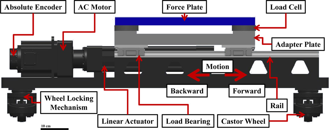
These perturbations needed to be produced in both the forward and backward directions (i.e., in and against the direction of walking, respectively, as shown in Figure 1) to induce both forward and backward phase shifts and to prevent subjects from compensating for anticipated perturbations in any one direction. The mechanism was also designed to withstand normal impact loads of up to 240 kg, since future experiments may involve subjects running.
Fig. 1.
Top view of the experimental setup. The subject walked along an 8 m walkway, stepping on the force plate in the center. The perturbation mechanism produced a perturbation at random when the subject stepped on it. The subject was asked to walk naturally from the starting position to the final position, after which the subject turned around and repeated.
A rod-style ball nut screw drive linear actuator (Model: SPL-RSA50-BN01-SK9-LMI-MP2-CLV, Tolomatic, Inc., Hamel, MN, USA) was used to move the force plate (i.e., contact surface) horizontally on top of the mechanism, Figure 2. This actuation system was custom made to achieve the specified displacement, speed, and loading requirements. The actuator was set in motion by a 2 kW AC servomotor (Model: R2AA13200DXP00M, SANYO DENKI CO., LTD., Tokyo, Japan). The motor was mounted in-line with the linear actuator to give a direct drive actuation. This yielded a faster and more efficient mechanism. The motor required a 3 phase, 220 VAC power input and was fused at 20 A. The rated torque of the motor was 6.37 Nm. It was controlled by a servo amplifier (Model: RS1A10AA, SANYO DENKI CO., LTD., Tokyo, Japan) with closed-loop position control using an optical, high resolution absolute encoder (Model: PA035, SANYO DENKI CO., LTD., Tokyo, Japan). The control scheme was a PID controller, where the PID gains could be set for the motor to get a desired performance response for the actuation system. The combination of the servomotor and the rod-style actuator fulfilled the desired specifications.
Fig. 2.
Schematic diagram of the translational perturbation mechanism with highlighted features. The force plate on top of the mechanism is able to measure the GRF of the subject.
A portable force plate (Model: 9260AA6, Kistler, Winterthur, Switzerland) was mounted onto an adapter plate on top of the actuator. When a subject stepped on the force plate, the mechanism would activate the motor after a predetermined time delay, thus setting the mechanism in motion. The adapter plate was guided by four linear load bearings through steel rails. These rails permitted only a horizontal motion of the adapter plate and the force plate, Figure 2. The end-effector of the actuator was attached to the center of the adapter plate from below. As a safety measure, the perturbation mechanism had two reed switches that could stop the actuator outside its specific range of motion.
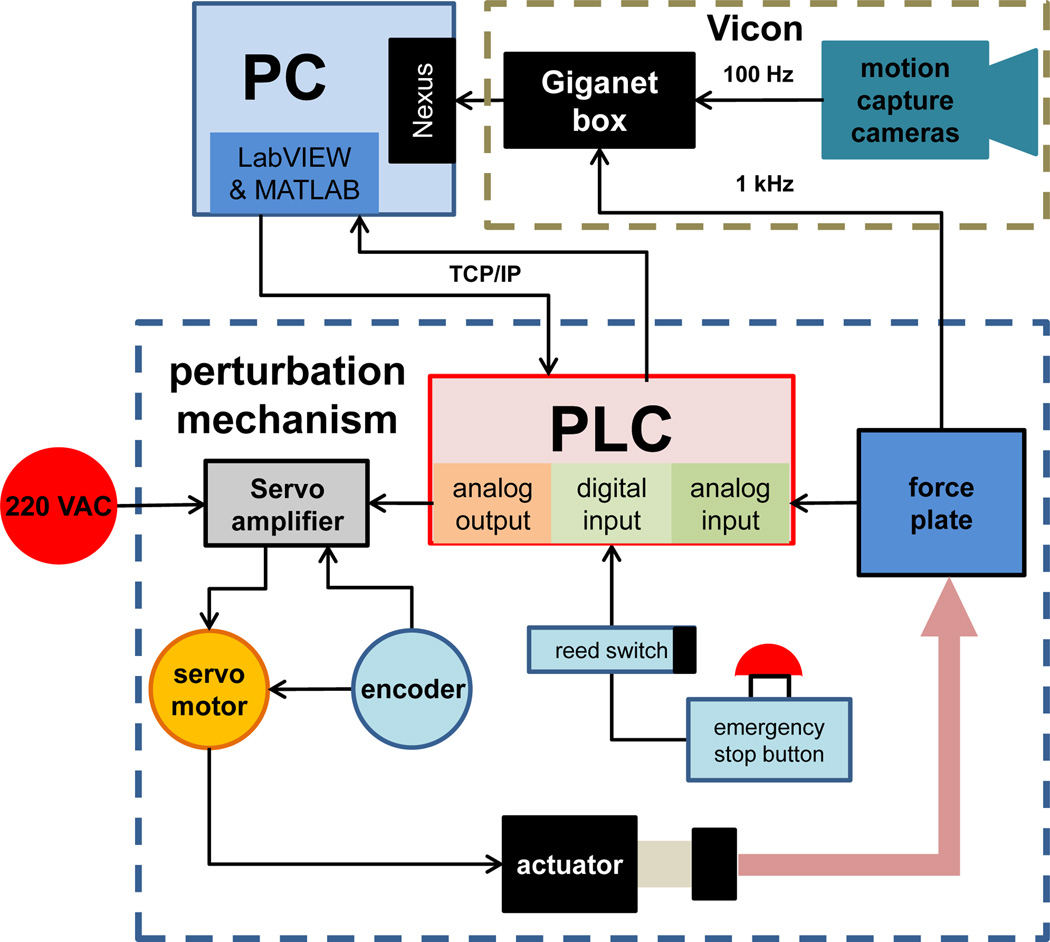
In order to integrate the sensing and actuation instruments of the perturbation mechanism, a Programmable Logic Controller (PLC, Model: CTC5220, Control Technology Corporation, MA, USA) was used. The PLC had multiple analog and digital I/Os. The reed switches and the emergency stop button were connected to the digital inputs. Two channels of the force plate were connected to the analog inputs of the PLC and a threshold signal was set to detect contact with the force plate. The digital and analog outputs of the PLC were connected to the servo amplifier, allowing control of the servomotor. Low-level algorithms were programmed in the PLC to control different actions of the motor. An external PC was used to oversee and direct these algorithms according to the experimental protocol described in the following section. The communication between the PLC and the computer was done using TCP/IP through an ethernet cable and an OPC server client. Figure 3 shows a general overview of the routing connections and hardware components.
Fig. 3.
Connection diagram of the perturbation mechanism with highlighted hardware. The perturbation mechanism reads the analog signal from the force plate to later actuate the platform through a servomotor. The motion capture cameras and Giganet box acquire and synchronize the experimental data to be stored and post-processed in a PC.
C. Experimental Procedure
The experimental protocol was approved by the Institutional Review Board at the University of Texas at Dallas. One subject was tested in order to validate the design of the mechanism. The human subject gave written informed consent of the experimental protocol prior to the experimentation. Anthropomorphic measurements (e.g., leg length, hip width, knee width, etc.) were taken from the subject and later entered into the motion capture software Nexus (Vicon, Oxford, UK) to create a 3D kinematic model with the help of Plug-in-Gait simulation software (Vicon, Oxford, UK). Reflective markers were attached to the subject’s bony landmarks to measure their kinematic behavior during the experiment. The subject was asked to wear comfortable clothes that would not interfere with motion capture.
The perturbation mechanism was embedded in the middle of an 8 m walkway (Figure 1), where the top of the force plate was level with the walkway surface. The experiment contained four sets of 72 trials, where each trial consisted of the subject walking from a fixed starting point, stepping with their right foot on the force plate in the middle of the walkway, and continuing to walk until the end of the walkway. Although force plate targeting does not significantly alter gait kinetics [23] or kinematics [24], the subject was given time before data collection to find a preferred starting point on the walkway to achieve consistent, clean contact on the force plate with minimal targeting. Handrails were located along the walkway to mitigate the risk of falling, but the subject did not use them at any time during the experiment.
The perturbation start time was chosen randomly as 100 ms, 250 ms, or 500 ms after initial contact (IC) with the force plate. At these specific times, the hip, knee, and ankle joints are typically in a monotonic region of the gait cycle as will be seen later [21]. Thus, a perturbation at these instants would not cause the joints to deviate from their usual range of motion during a steady gait cycle. A supplemental video of these perturbation conditions is available for download.
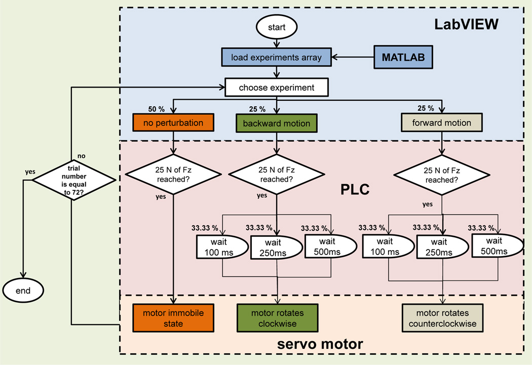
The PLC initiated one of three preprogrammed subroutines whenever the subject stepped on the force plate (triggered by a vertical force of 25 N). The first option set the motor into an immobile state for no perturbation. The second and third options respectively set the mechanism into forward or backward motion—in or against the direction of walking—after a randomized delay of 100 ms, 250 ms, or 500 ms from IC (Figure 2). The force plate traveled a distance of 5 cm over 100 ms in either direction. In order to decide what perturbation condition would occur, a randomized array of conditions was created using MATLAB (MathWorks, Natick, MA, USA). This array was configured to give non-perturbations a 50% probability of incidence, and the forward or backward conditions (5 cm displacement in 100 ms) a 25% probability of incidence. For the forward or backward conditions the perturbation timings were randomized with equal probability. This array was set into LabVIEW (National Instruments, Austin, TX, USA) and used to control the onset of each subroutine programmed in the PLC, Figure 4.
Fig. 4.
Flow diagram of the algorithm used to control the perturbation mechanism across all trials. The percentages represent the probability of incidence of each experiment across all trials.
D. Data Acquisition
Besides serving as a triggering device, the force plate mounted on the perturbation mechanism was also used to collect the subject’s GRF at a sample rate of 1 kHz. A second-order low-pass Butterworth filter (8 Hz cutoff) was implemented in MATLAB to post-process the force plate’s raw data. The main purpose of this filter was to eliminate noise from the GRF signal.
Kinematic data was collected by ten motion capture cameras (Model: T20S, Vicon, Oxford, UK) that measured the 3D spatial coordinates of reflective markers attached to bony landmarks on the subject’s body. The data acquisition rate for the cameras was set to 100 Hz. The hip, knee, and ankle joint angle kinematics were captured for both legs during the experiment. All data collected from the force plate and cameras were synchronized through the use of a Giganet box (Vicon, Oxford, UK). This data was then stored in Nexus, which directly filtered and post-processed the kinematic data. Impulses in the force plate measurements and the velocity of the heel marker were used to define the gait cycle period.
E. Statistical Analysis
A 2-tail t-test was used to analyze the collected data using MATLAB. The end times of each perturbed gait cycle were compared to the end times of each non-perturbed gait cycle. A p-value less than 0.05 would indicate a statistical difference in the time durations, thus confirming the hypothesis stated in Section II-A.
III. Experimental Results
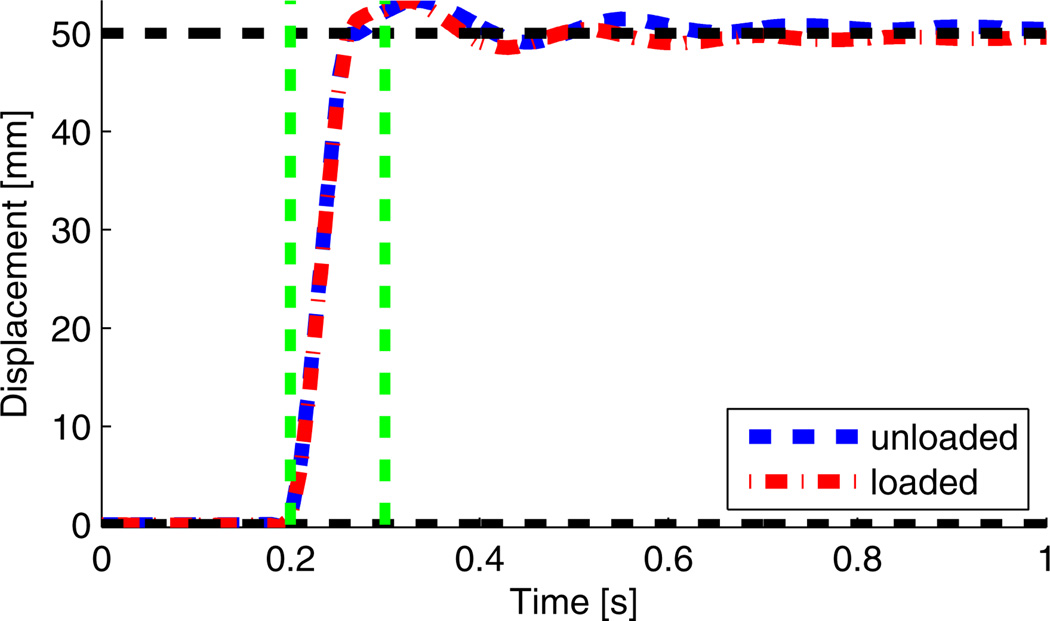
Prior to performing the human subject study, we validated the ability of the mechanism to produce the desired perturbation trajectory. The magnitude and timing of the perturbation were corroborated by the motion capture system (Vicon, Oxford, UK). Figure 5 shows the perturbation produced by the mechanism with and without a human stepping on it. Observe that the perturbation has a 5 cm magnitude over a span of approximately 100 ms. Further analysis of the perturbation showed that it has a 40 ms rise time.
Fig. 5.
Motion of the perturbation unloaded (blue dashed line) and loaded (red dash-dot line) in the forward direction. Green dashed vertical lines show the time span of the perturbation, roughly 100 ms. Black dashed horizontal lines are the initial and final desired values of the perturbation.
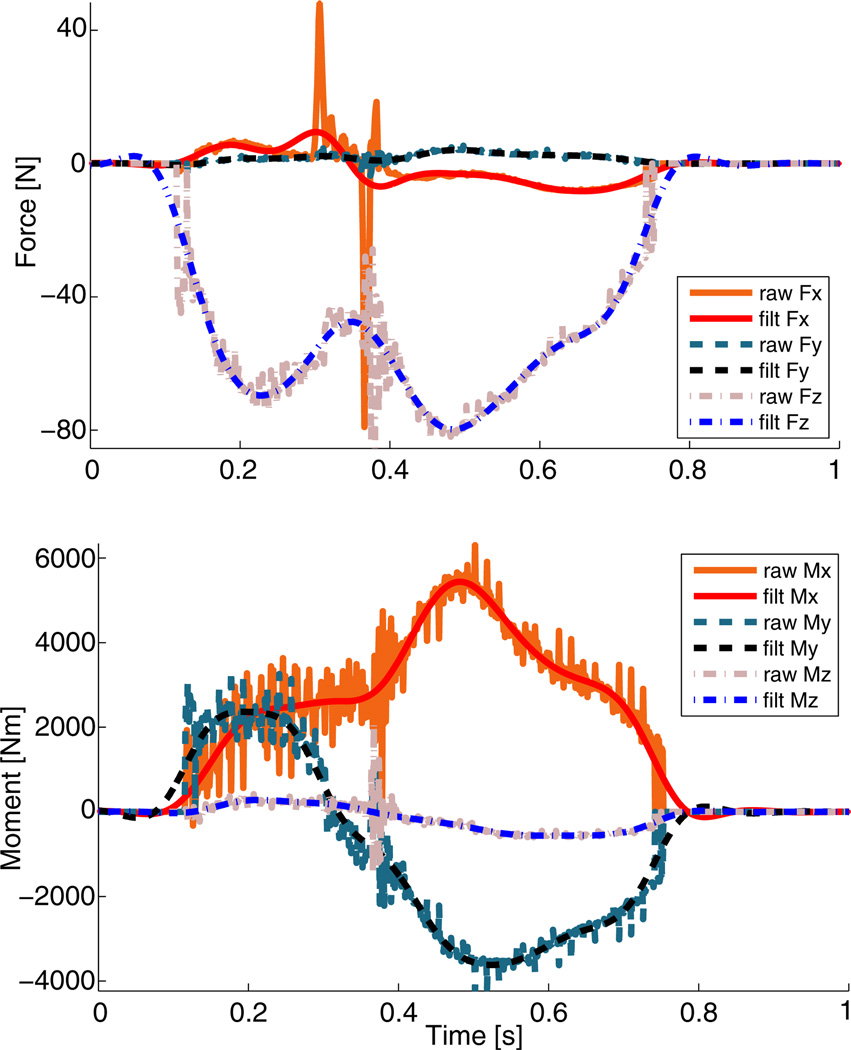
The human subject study aimed to validate both the sensing abilities of the mechanism and its effect on the human gait cycle. Figure 6 shows how the filter effectively removed the high frequency noise in the signals from the force plate. The COP trajectory in Figure 7 was calculated from the filtered force plate signals. The non-perturbed COP trajectory closely resembles that of normal walking [21].
Fig. 6.
Comparison between raw and filtered (filt) forces and moments collected from the loaded force plate. Top: Fx, Fy, and Fz are the forces in the x, y, and z axes, respectively. Bottom: Mx, My, and Mz are the moments in the x, y, and z axes, respectively.
Fig. 7.
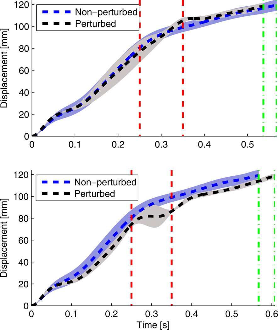
COP trajectory during stance with backward (top) and forward (bottom) perturbations. Red dashed vertical lines show the time span of the perturbation, i.e, 250 ms to 350 ms. Green dash-and-dot vertical lines show the time difference between the perturbed and non-perturbed stance periods.
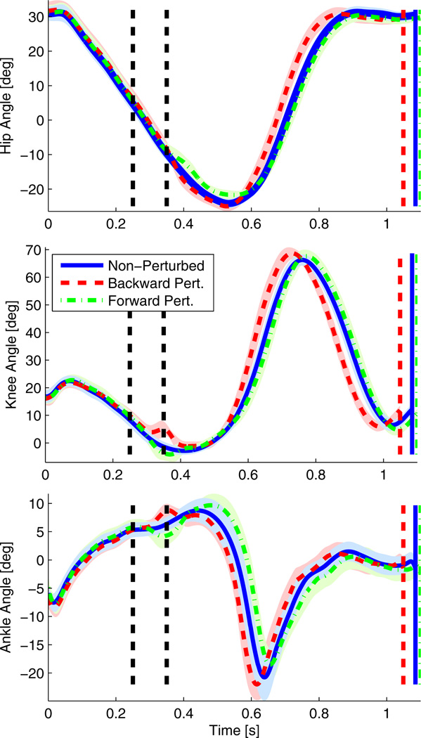
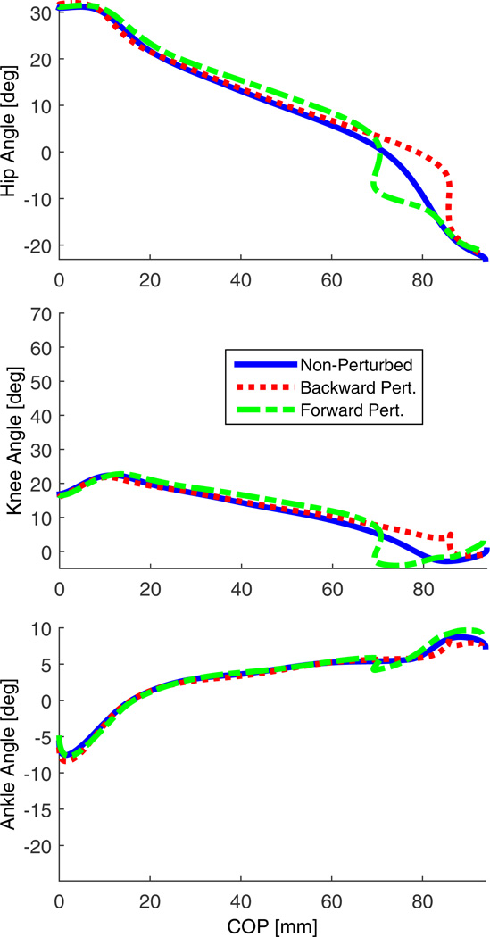
A phase shift in both kinetics and kinematics can be observed after forward and backward perturbations. Focusing on the 250 ms onset condition, Figure 8 shows that backward perturbations caused a noticeable acceleration of the COP towards the toe, whereas forward perturbations caused a deceleration of the COP trajectory. Figure 8 compares the perturbed and non-perturbed kinematics of the hip, knee, and ankle joints of the initiating leg (i.e., the leg contacting the force plate) through the gait cycle. A kinematic phase shift is clearly observed, thus supporting the hypothesis stated in Section II-A. Figure 9 shows the COP encoding this kinematic phase shift as a phase variable during stance, resulting in synchrony between the perturbed and non-perturbed trajectories as observed with rotational perturbations in [14]. The results for the 100 ms perturbation onset are similar but are withheld due to space limitations. The 500 ms onset produced inconclusive results, likely because the subject was in the process of stepping off the force plate.
Fig. 8.
Hip, knee, and ankle angles of the initiating leg (i.e., leg stepping on the force plate) over time with and without perturbations 250 ms after IC. Black dashed vertical lines indicate the time span of the perturbation (i.e, 250 ms to 350 ms). Blue solid, red dashed, and green dash-and-dot vertical lines show the time difference between the perturbed and non-perturbed gait cycles. Shaded regions correspond to one SD away from the mean.
Fig. 9.
Mean hip, knee, and ankle angles of the initiating leg (i.e., leg stepping on the force plate) over mean COP during stance with and without perturbations 250 ms after IC. Note that the perturbed trajectories appear to converge back to the nominal trajectories over the phase variable candidate.
Focusing again on the 250 ms onset condition, Table I shows the p-values in the analysis of the hypothesized difference between the perturbed and non-perturbed gait cycles. This table also shows the statistical analysis of the time during the stance period only, which is when the COP could be measured. According to Section II-E, the p-values shown in this table suggest a statistical difference in the gait cycle and stance period durations. This demonstrates that the perturbation exerted by the machine can produce a backward or forward shift of the joint kinematics over time. Table II displays the mean and standard deviation (SD) values related to the statistical analysis of the time shift hypothesis. It can be noticed that a backward perturbation yields a shorter gait cycle and stance period whereas a forward perturbation yields a longer gait cycle and stance period. The 100 ms perturbation onset produced similar statistics.
TABLE I.
Time shift hypothesis [P-values]
| Condition | Gait cycle period | Stance period time |
|---|---|---|
| BWD pert. | <<0.05 | 0.0022 |
| FWD pert. | 0.0234 | <<0.05 |
P-values for the time shift hypothesis applied to both the stance period and the gait cycle period.
TABLE II.
Time shift hypothesis [Mean & SD]
| Condition | Gait cycle period [s] | Stance period [s] | ||
|---|---|---|---|---|
| Mean | SD | Mean | SD | |
| Non-pert. | 1.084 | 0.028 | 0.590 | 0.019 |
| BWD pert. | 1.048 | 0.024 | 0.575 | 0.013 |
| FWD pert. | 1.100 | 0.034 | 0.612 | 0.019 |
Mean and SD values for the time shift hypothesis.
IV. Discussion
These results demonstrate that this perturbation mechanism is appropriately designed to study the phase variable hypothesis. The mechanism was able to perturb the joint angles during the stance period of the gait cycle at specific times. Tables I and II show the p-values, means, and SDs associated to the statistical tests done for the hypothesis stated in Section II-A. In particular, the perturbations caused a phase shift in both kinetics (Figure 7) and kinematics (Figure 8) by accelerating or slowing the gait cycle as hypothesized. Therefore, this mechanism can be used to investigate the potential relationship between the kinematic response and phase variable candidates as in Figure 9. This preliminary phase-based analysis of the stance period will soon be extended to the entire gait cycle with phase variables that are well defined during both stance and swing.
Compared to a slip where the distance and time of gliding cannot be controlled [17]–[20], the perturbation mechanism built is able to accurately perturb an exact magnitude over a specific period of time. In addition, the friction coefficient between the force plate and the person’s foot is enough to avoid true slipping. Another difference is that the mechanism can reach greater accelerations with smaller displacements than those normally experienced during a slip. This allows the subject to have a faster response to the perturbation without halting steady gait.
Future work will involve experiments with more subjects, more perturbation conditions, and additional statistical tests with a phase variable capable of parameterizing the complete gait cycle. Electromyography (EMG) measurements will also be studied to determine whether a phase variable can characterize the timing of muscle activations. Additional perturbation timings will be thoroughly analyzed to evaluate the robustness of the phase variable hypothesis across different instances of the gait cycle. Therefore a study involving ten human subjects is planned with four sets of 72 trials per subject using the perturbation mechanism.
V. Conclusions
This paper presented the design and experimental validation of a translational perturbation mechanism for inducing phase shifts in the human gait cycle. Not only can this mechanism be used to study the phase variable hypothesis, it can also be used to study other biomechanical properties of human gait. One example could be evaluating dynamic joint impedance as in [16] where perturbation experiments were essential to the understanding of this biomechanical property. The mechanism could also be used to study various balance metrics during standing, walking, and running. Future work will focus on identifying a robust phase variable for the entire human gait cycle, which could be a major breakthrough for non-steady gait analysis and controlling robotic prostheses and exoskeletons [10]–[12].
Supplementary Material
Acknowledgments
The authors wish to thank Shepherd Controls (Allen, TX, USA) for assembling the perturbation mechanism. We also thank Elliot Rouse for inspiring the mechanism design and Perrine Mathieu for helping in the composition of this paper.
Robert D. Gregg, IV, Ph.D., holds a Career Award at the Scientific Interface from the Burroughs Wellcome Fund. This work was also supported by the Eunice Kennedy Shriver National Institute of Child Health & Human Development of the National Institutes of Health under Award Number DP2HD080349. The content is solely the responsibility of the authors and does not necessarily represent the official views of the NIH. Dario J. Villarreal holds a Graduate Fellowship from the National Council of Science and Technology (CONACYT) from Mexico.
References
- 1.Vogelstein RJ, Etienne-Cummings R, Thakor NV, Cohen AH. Phase-dependent effects of spinal cord stimulation on locomotor activity. IEEE Transactions on Neural Systems and Rehabilitation Engineering. 2006 Sep.14(3):257–265. doi: 10.1109/TNSRE.2006.881586. [DOI] [PubMed] [Google Scholar]
- 2.Dzeladini F, Van Den Kieboom J, Ijspeert A. The contribution of a central pattern generator in a reflex-based neuromuscular model. Frontiers in Human Neuroscience. 2014;8(371) doi: 10.3389/fnhum.2014.00371. [DOI] [PMC free article] [PubMed] [Google Scholar]
- 3.Geyer H, Herr H. A muscle-reflex model that encodes principles of legged mechanics produces human walking dynamics and muscle activities. IEEE Transactions on Neural Systems and Rehabilitation Engineering. 2010;18(3):263–273. doi: 10.1109/TNSRE.2010.2047592. [DOI] [PubMed] [Google Scholar]
- 4.Taghvaei A, Hutchinson SA, Mehta PG. A coupled oscillators-based control architecture for locomotory gaits. 53rd IEEE Conference on Decision and Control. 2014:3487–3492. [Google Scholar]
- 5.Tilton AK, Hsiao-Wecksler ET, Mehta PG. Filtering with rhythms: Application to estimation of gait cycle. American Control Conference. 2012:3433–3438. [Google Scholar]
- 6.Revzen S, Guckenheimer J. Estimating the phase of synchronized oscillators. Physical Review E. 2008;78(5):051907. doi: 10.1103/PhysRevE.78.051907. [DOI] [PubMed] [Google Scholar]
- 7.Grizzle J, Westervelt E, Chevallereau C, Choi J, Morris B. Feedback Control of Dynamic Bipedal Robot Locomotion. Boca Raton, FL: CRC Press; 2007. [Google Scholar]
- 8.Ramezani A, Hurst JW, Akbari Hamed K, Grizzle JW. Performance analysis and feedback control of ATRIAS, a three-dimensional bipedal robot. Journal of Dynamic Systems, Measurement, and Control. 2013 Dec;136(2):021012. [Google Scholar]
- 9.Sreenath K, Park H-W, Poulakakis I, Grizzle JW. A compliant Hybrid Zero Dynamics controller for stable, efficient and fast bipedal walking on MABEL. The International Journal of Robotics Research. 2010 Sep.30(9):1170–1193. [Google Scholar]
- 10.Gregg RD, Lenzi T, Hargrove LJ, Sensinger JW. Virtual constraint control of a powered prosthetic leg: From simulation to experiments with transfemoral amputees. IEEE Transactions on Robotics. 2014;30(6):1455–1471. doi: 10.1109/TRO.2014.2361937. [DOI] [PMC free article] [PubMed] [Google Scholar]
- 11.Holgate MA, Sugar TG, Bohler AW. A novel control algorithm for wearable robotics using phase plane invariants. IEEE Int. Conf. Robotics & Automation. 2009:3845–3850. [Google Scholar]
- 12.Sugar TG, Bates A, Holgate M, Kerestes J, Mignolet M, New P, Ramachandran RK, Redkar S, Wheeler C. Limit cycles to enhance human performance based on phase oscillators. Journal of Mechanisms and Robotics. 2014 Feb;7:1–8. [Google Scholar]
- 13.Villarreal DJ, Gregg RD. A survey of phase variable candidates of human locomotion. IEEE Engineering in Medicine and Biology Conf. 2014:4017–4021. doi: 10.1109/EMBC.2014.6944505. [DOI] [PMC free article] [PubMed] [Google Scholar]
- 14.Gregg RD, Rouse EJ, Hargrove LJ, Sensinger JW. Evidence for a time-invariant phase variable in human ankle control. PLoS ONE. 2014 Jan.9(2):e89163. doi: 10.1371/journal.pone.0089163. [DOI] [PMC free article] [PubMed] [Google Scholar]
- 15.Rossignol S, Dubuc R, Gossard J. Dynamic sensorimotor interactions in locomotion. Physiological reviews. 2006 Jan.86(1):89–154. doi: 10.1152/physrev.00028.2005. [DOI] [PubMed] [Google Scholar]
- 16.Rouse EJ, Hargrove LJ, Perreault EJ, Peshkin M, Kuiken T. Development of a mechatronic platform and validation of methods for estimating ankle stiffness during the stance phase of walking. Journal of biomechanical engineering. 2013;135(8):81009. doi: 10.1115/1.4024286. [DOI] [PMC free article] [PubMed] [Google Scholar]
- 17.Trkov M, Yi J, Liu T, Li K. Shoe-floor interactions during human slip and fall: Modeling and experiments. ASME Dynamic Systems and Control Conference. 2014 [Google Scholar]
- 18.Haynes C, Lockhart TE. Evaluation of gait and slip parameters for adults with intellectual disability. Journal of biomechanics. 2012 Sep.45(14):2337–2341. doi: 10.1016/j.jbiomech.2012.07.003. [DOI] [PMC free article] [PubMed] [Google Scholar]
- 19.Forner-Cordero A, Ackermann M, de Lima Freitas M. A method to simulate motor control strategies to recover from perturbations: application to a stumble recovery during gait. IEEE Engineering in Medicine and Biology Conf. 2011:7829–7832. doi: 10.1109/IEMBS.2011.6091929. [DOI] [PubMed] [Google Scholar]
- 20.Shirota C, Simon AM, Rouse EJ, Kuiken TA. The effect of perturbation onset timing and length on tripping recovery strategies. IEEE Engineering in Medicine and Biology Conf. 2011:7833–7836. doi: 10.1109/IEMBS.2011.6091930. [DOI] [PubMed] [Google Scholar]
- 21.Winter D. In: Biomechancis and Motor Control of Human Movement. Wiley J, Inc S, editors. Hoboken, NJ: 2009. [Google Scholar]
- 22.van Doornik J, Sinkjaer T. Robotic platform for human gait analysis. IEEE Transactions on Biomedical Engineering. 2007;54(9):1696–1702. doi: 10.1109/TBME.2007.894949. [DOI] [PubMed] [Google Scholar]
- 23.Grabiner MD, Feuerbach JW, Lundin TM, Davis BL. Visual guidance to force plates does not influence ground reaction force variability. Journal of biomechanics. 1995;28(9):1115–1117. doi: 10.1016/0021-9290(94)00175-4. [DOI] [PubMed] [Google Scholar]
- 24.Verniba D, Vergara ME, Gage WH. Force plate targeting has no effect on spatiotemporal gait measures and their variability in young and healthy population. Gait & posture. 2015;41(2):551–556. doi: 10.1016/j.gaitpost.2014.12.015. [DOI] [PubMed] [Google Scholar]
Associated Data
This section collects any data citations, data availability statements, or supplementary materials included in this article.


