Abstract
Robot-assisted minimally invasive surgery (MIS) has gained popularity due to its high dexterity and reduced invasiveness to the patient; however, due to the loss of direct touch of the surgical site, surgeons may be prone to exert larger forces and cause tissue damage. To quantify tool–tissue interaction forces, researchers have tried to attach different kinds of sensors on the surgical tools. This sensor attachment generally makes the tools bulky and/or unduly expensive and may hinder the normal function of the tools; it is also unlikely that these sensors can survive harsh sterilization processes. This paper investigates an alternative method by estimating tool–tissue interaction forces using driving motors' current, and validates this sensorless force estimation method on a 3-degree-of-freedom (DOF) robotic surgical grasper prototype. The results show that the performance of this method is acceptable with regard to latency and accuracy. With this tool–tissue interaction force estimation method, it is possible to implement force feedback on existing robotic surgical systems without any sensors. This may allow a haptic surgical robot which is compatible with existing sterilization methods and surgical procedures, so that the surgeon can obtain tool–tissue interaction forces in real time, thereby increasing surgical efficiency and safety.
Keywords: sensorless force estimation, motor current, decoupling, robot-assisted minimally invasive surgery
1. Introduction
Robot-assisted MIS has gained in popularity around the world because it can improve surgical accuracy and dexterity and minimize trauma to the patient, and it has made a large impact on many kinds of surgeries [1]. However, because the surgeon cannot directly touch the surgical site, the tactile information is lost, which is a very important cue for the surgeon to conduct the surgical operation. The lack of haptic feedback is believed to have an adverse effect on surgical efficiency and safety [2].
To obtain the tool–tissue interaction forces, researchers have tried to attach different kinds of force sensors on surgical tools [3]. For example, Fischer et al. integrated strain gauges on the jaws of a surgical grasper to measure 2-DOF bending forces and axial forces [4]; Menciassi and Payne applied strain gauges on the jaws of microgrippers and forceps for measuring grasping forces and tissue properties in microsurgery [5,6]. Hammond et al. printed strain gauges on a surgical forceps to measure pinch force [7]; Gafford et al. used alternative manufacturing methods to integrate strain gauges into grippers for pinch force measurement [8]. Seibold and Kuebler developed a six-axis force–torque sensor with strain gauges and attached it at the distal end of the surgical tool shaft to measure interaction forces at the tip [9,10]. Gray and Fearing used capacitive sensor arrays for tissue palpation [11], and Sokhanvar et al. used piezoelectric sensor arrays for force measurement and tissue palpation [12]. Fetter et al. used vibrotactile sensors for tissue palpation [13], and Peirs et al. used optical fiber sensors to measure tool–tissue interaction force [14].
Despite the successes of these methods at measuring tool–tissue interaction forces, the attachment of force sensors may lead to some other problems. First, due to the small size of surgical tools, the sensor attachment is difficult to implement, making the tools bulky and/or very costly and potentially impairing their normal use. Second, the surgical tools need to go through steam sterilization in an autoclave, and this requires saturated steam to heat the tools up to 121 °C at 103 kPa (gauge pressure) for at least 15 min; the intensive heat, pressure, and humidity may destroy sensors [3] which invalidates this approach for force feedback in surgical tools. Furthermore, these sensor-based methods do not scale well for force sensing in multiple DOFs.
This paper explores the possibility to use motor current for sensorless estimation of tool–tissue interaction forces. Jeong and Li had used a similar method to estimate the cutting forces on a milling machine and on a computer numerically controller (CNC) turning center [15,16]. Tholey et al. had done related work by estimating force on a surgical grasper with supplied motor voltage [17], but the accuracy of this approach was not acceptable. In this paper, we present the decoupling of 3-DOF surgical grasper motions, and extend our work in Ref. [18] by demonstrating clinically relevant tasks involving force sensing on a new robotic surgical grasper prototype.
2. Decoupling Mechanism
It will be more accurate to estimate the tool–tissue interaction forces if the robot has a decoupled driving system, since each motor will only drive 1 DOF and will not interfere with other motions. However, the existing surgical tools for robot-assisted MIS in the market tend to have coupled motions. For example, the EndoWrist surgical tools on the daVinci Surgical System (Intuitive Surgical) have coupled grasp and yaw motions (Fig. 1). To obtain accurate force estimation on a surgical tool, it is a prerequisite to decouple the motions.
Fig. 1.

Tool tip motion coupling on the EndoWrist
Figure 2 explains how the tool's yaw motion is coupled with the grasp jaws' position, which relates both pitch and grasp motions. For clear demonstration, the grasp joint is assumed to be in the same plane with the yaw joint. The distance between the yaw joint and the grasp joint is constant; the cable lengths from points A and B to the jaw are constant. When the yaw motion is zero, the jaw is in line with the centers of the yaw pulley and grasp pulley; when the yaw DOF displaces by an angle θ, the jaw position deviates from the center line by θ (assuming 1:1 scaling—the yaw pulley has the same diameter as the grasp pulley).
Fig. 2.
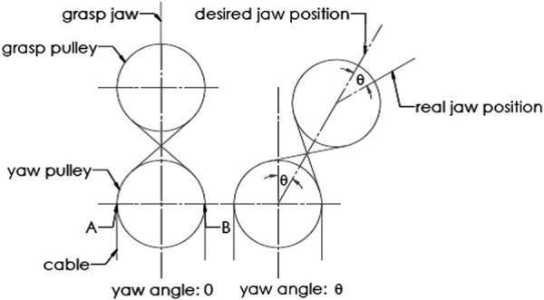
Motion coupling between the jaw position and yaw motion
To decouple the motions, a mechanism based on the planetary gear theory is proposed [19]. The geometry of the mechanical relationships of this mechanism is shown in Fig. 3. Cable 1 and cable 4 are a pair of cables that drive one jaw. With the yaw angle being zero, the path length of cable 1 can be calculated as (see Nomenclature section)
Fig. 3.
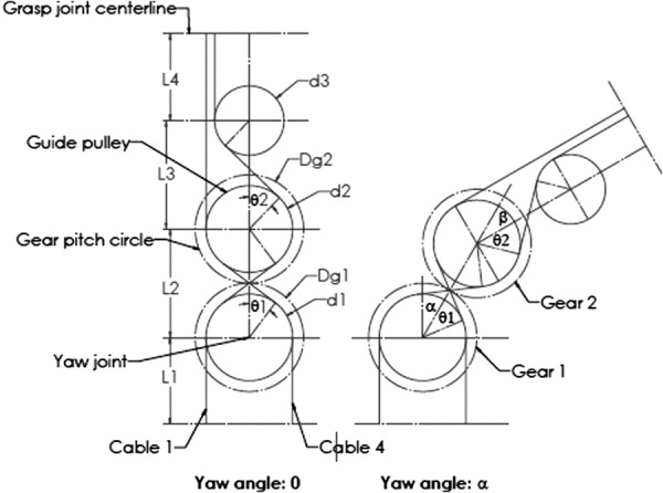
Kinematics of decoupling
| (1) |
| (2) |
| (3) |
The path length of cable 4 takes a similar form, as do the cables that drive the other jaw. The center distance L and pulley diameter d should be chosen to preclude interference, as shown in Fig. 3.
When the yaw motion has a rotation angle α, the path length of cable 1 can be represented by
| (4) |
The difference between and is
| (5) |
To make the jaw motion decoupled with the yaw DOF, the difference between and should be zero, which means
| (6) |
To impose this constraint on the mechanism, a planetary gear system including gear 1 (the sun gear), gear 2 (the planet gear), and a carrier is applied. Based on the mechanical relationships in a planetary gear system
| (7) |
(, , are velocities of gears and the carrier.)
With representing time
| (8) |
From Eq. (7), it is noticed that if = 0 (fix the sun gear)
| (9) |
If (pulley diameter ratio) is set equal to , then the decoupling requirement in Eq. (6) can be satisfied.
If choosing a different constraint in the planetary gear system rather than = 0, for example, ω1 = −ωH, then
| (10) |
In this case, if equals half , then the decoupling requirement is again satisfied.
In conclusion, if the gear diameter ratio and another constraint in the planetary gear system are known, the pulley diameter ratio can be chosen to decouple the grasp jaw motion from the yaw motion.
To apply this theory in a surgical grasper design, there are three design steps, each with multiple options (Table 1, based on design theory presented in Ref. [20]). After going through all the design possibilities, the design with gear ratio 1:1, fixing the sun gear, and choosing the carrier as the driving component gives the most compact design, as shown in Fig. 4. The planetary gear system will drive the yaw DOF, and the housing (rigidly attached with the second gear) is the output of the yaw DOF; the cables driving the two jaws pass the yaw joint through a series of idler pulleys.
Table 1.
Design choices for a surgical grasper
| Design steps | Design choices | |||
|---|---|---|---|---|
| 1. Select gear ratio |  |
1:2 | 1:3 | ⋯ |
| 2. Add a constraint | 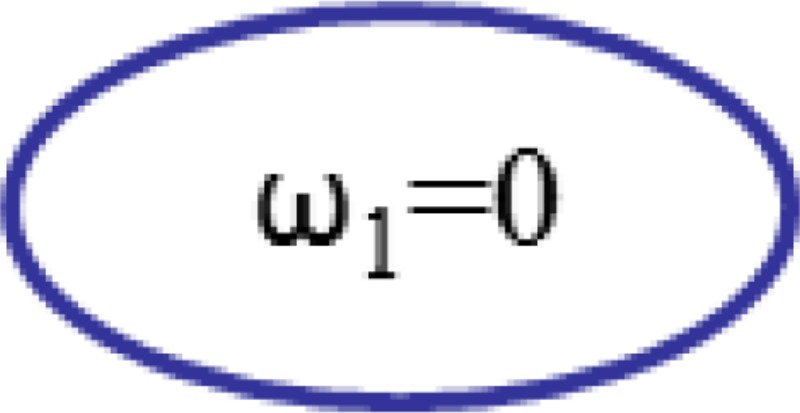 |
⋯ | ||
| 3. Select driving component |  |
Gear 2 | Gear 1 | ⋯ |
Fig. 4.
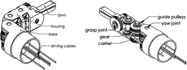
A compact, decoupled surgical grasper design
The design in Fig. 4 has a fixed sun gear ( = 0); gear 1 and gear 2 have the same diameter for space efficiency. Based on the decoupling theory discussed above, the pulley diameter ratio is set to be 1:1. According to the planetary gear theory
| (11) |
Therefore, = 2 . In this design, the carrier is attached on a driving pulley, to be chosen as the driving link, and gear 2 is the output of the yaw DOF. This implies that the yaw output angle is two times the input, as demonstrated in Fig. 3.
3. Sensorless Force Estimation
3.1. Dynamic Modeling.
Because the robot has a decoupled driving mechanism, and each motor drives a separate DOF, a dynamic model of a single DOF is shown in Fig. 5. (The reader is also referred to similar modeling in Ref. [20].) The motor drives all the rotational components on this DOF through a gear set. The total motor torque can be calculated as in the following equation:
Fig. 5.
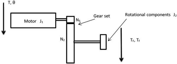
Dynamic modeling of a single DOF
| (12) |
Based on a 66:1 planetary gearhead (used in the prototypes described below), N1/N2 = 1/66. Substituting into Eq. (12)
| (13) |
Because all the rotational components in the prototype are fabricated using plastic and are small in size, compared with the motor inertia of J1 = 2.7 g cm2, the inertia of the rotational components can be neglected (J2/4356 < 0.0005 g cm2). According to DC motor theory, the motor current has a linear relation with motor torque (K = torque constant)
| (14) |
Since the surgical motions are slow, the dynamic effect is assumed to be minimal; if the friction in the mechanism can also be compensated in some way (by calibrating, for example), it is assumed that the interaction force can be estimated from the respective driving motor's current. These assumptions are explored further through experiments as described later in this paper.
3.2. Force Estimation on a 3-DOF Robotic Surgical Grasper.
To test the performance of the sensorless force estimation method, three prototypes have been built and tested in scenarios approaching real surgical applications. Figure 6 shows the first version prototype, which is a 3-DOF surgical grasper prototype fabricated using 3D printing with tool tip diameter of approximately 40 mm; each DOF is driven by a motor (Faulhaber 2224U012S DC motor in combination with 66:1 planetary gearhead) through braided polyethylene cable; and all the joints in the prototype are equipped with ball bearings to reduce friction. This scaled prototype has been tested and shows an acceptable result in terms of accuracy and latency [21]. Figure 7 shows the second prototype, which is also fabricated by 3D printing, but with much smaller size (with tool tip diameter around 15 mm, this is near the strength limitations of 3D-printed plastic components); all the joints in the tool tip are equipped with journal bearings to mimic the metal–metal friction surface on an actual surgical tool, and all the joints in the driving unit are equipped with ball bearings to reduce friction. This small-sized prototype has been tested [22], and the results demonstrated that with appropriate calibration, this small-sized prototype could achieve similar performance to that of the larger-scale version. In this paper, we focus on the third version prototype. Compared with the second version, a stainless steel tube (with diameter 16 mm) is used to replace the wooden platform connecting the motor frame with tool tip and to encase all the transmission cables; also the motor frame is designed with a more compact form to facilitate the tool's attachment on a robotic arm. Figure 8 shows the comparison between the third version prototype and an EndoWrist surgical grasper typically used with the daVinci Surgical System. A passive master control with 3 DOF was also fabricated, with potentiometers attached on each joint (Fig. 9). The driving motors in the surgical grasper prototype are under proportional-integral-derivative position control, with position commands sent from the passive master device; the motors' current signals go through a low-pass filter with a cutoff frequency of 3 Hz. The data is sampled at 2 kHz.
Fig. 6.
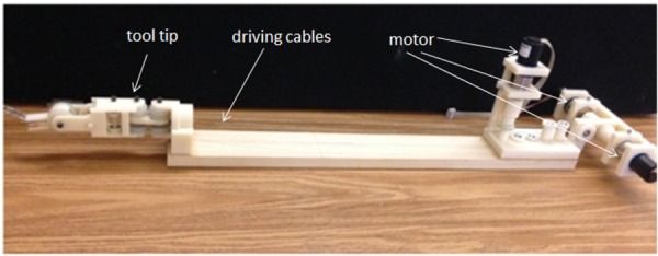
The first version prototype
Fig. 7.
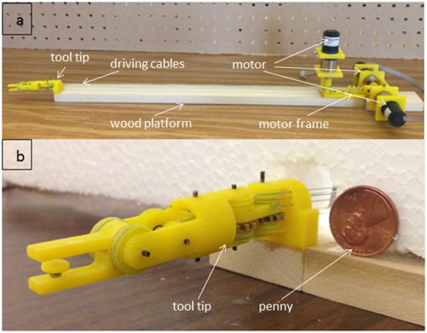
The second version prototype
Fig. 8.

The third version prototype
Fig. 9.
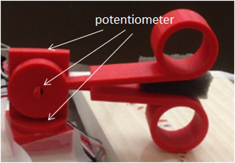
3-DOF master control equipped with potentiometer-based joint encoders
Force estimation experiments have been implemented on the third version prototype on grasp, pitch, and yaw DOFs separately, with the experiment setup shown in Fig. 10. A force-sensitive resistor (FlexiForce A201, 4.4 N force range) was used to measure the interaction force. The interaction force estimation on each jaw can be obtained from their driving motors separately based on the motor current, and the grasp force is estimated by averaging the effects of the two jaws; the pitch force estimation can be obtained from the driving motor of the contacting jaw (with the force sensor); and the yaw force estimation can be obtained from the driving motor of the yaw DOF.
Fig. 10.
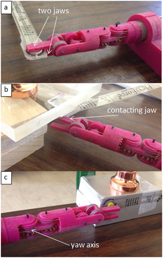
Force estimation experiment setup on (a) grasp DOF, (b) pitch DOF, and (c) yaw DOF
To check the robustness of this force estimation method, long steady inputs (lasting more than 25 s) were applied on the grasp DOF. Figure 11(a) shows the results of repeated testing over a range of forces; compared with the large-scale prototype in Ref. [21], it is found that due to the removal of ball bearings on the tool tip, the steady-state estimation error is no longer constant for long steady input. The force estimation is linearly increasing with the force measurement, with a ratio of 1.28 (this value comes from the slope of the linear curve fit of force estimation versus force measurement for long steady input, shown in Fig. 11(b). A calibration coefficient of 1/1.28 is applied to all the force estimation data to compensate for the effect of friction.
Fig. 11.
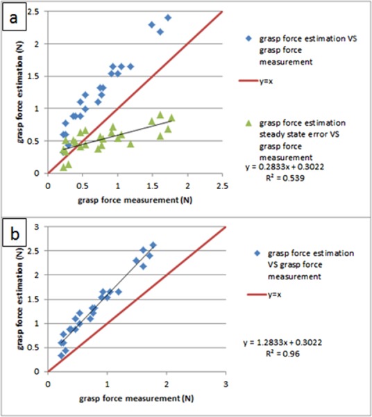
(a) Steady-state estimation error is no longer constant as in Ref. [21] and (b) calibration between the force estimation and the force measurement
Figure 12 shows the calibrated experiment result for long steady input; the force shape comparisons between force estimation and force measurement are shown versus time in Fig. 12(a), and the repeated testing results are shown in Fig. 12(b). We can notice that, after calibration, the steady-state error is constant regardless of the load, around 0.24 N; this error will be used to characterize the accuracy of this force estimation method. Similar to the results on the large-scale prototype in Ref. [21], there is an initial peak at the beginning of the force estimation, which is mainly due to the dynamic effect; then the amplitude decreases slowly until it settles to a steady state, which is slightly larger than the force measurement. This is believed to be caused by the friction in the mechanism. The repeated testing results demonstrate the robustness of this force estimation method.
Fig. 12.
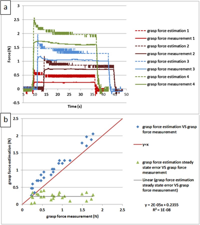
Calibrated force estimation result for long steady input on grasp DOF: (a) comparison between the force estimation and the force measurement versus time and (b) the repeated testing results
Since typical surgical motions last less than 2 s, the force estimation method was tested with short steady inputs (lasting about 2 s) on the grasp DOF. Figure 13 shows the results; the force shape comparisons between force estimation and force measurement are shown versus time in Fig. 13(a), and the repeating test results are shown in Fig. 13(b). Compared with the results for the long steady input in Fig. 12, the performance for the short steady input is similar; the only difference is that the estimation error becomes larger and is linearly proportional to the load; this is because in the shorter time period after the loading process, the dynamic effect will play a more important role, thus inflating the estimation error. This contradicts our initial assumption about dynamic effects in Sec. 3.1, which indicates that accurate dynamic modeling of the system may help to mitigate this problem.
Fig. 13.
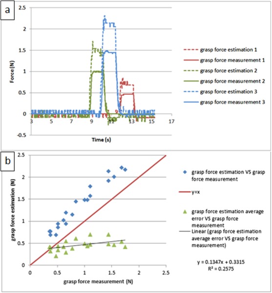
The calibrated experiment result for short steady input on grasp DOF: (a) comparison between the force estimation and the force measurement versus time and (b) repeated testing results
Since the frequency of voluntary surgical motions is under 2 Hz [23], to test the stability of the force estimation method under this characteristic motion condition, periodic inputs were manually applied on the grasp DOF at about 2 Hz. Figure 14 shows the testing results by comparing the force estimation and the force measurement; the shape comparisons are shown in Fig. 14(a), and two input cycles are shown in detail in Fig. 14(b). It is demonstrated that the force estimation can follow the characteristic shape of the force measurement, with almost no latency (the time gap between force estimation peak and its corresponding force measurement peak). Compared with the testing result for the large scale prototype in Ref. [21], the performance on the small-sized prototype is similar, except that the force estimation signal here is a bit noisy. This is because, due to differences in jaw geometry between the two versions, the operating speed on the small-sized prototype is twice as high as that of the large scale prototype (0.5 rad/s), which will enlarge the dynamic effect and worsen the force estimation performance.
Fig. 14.
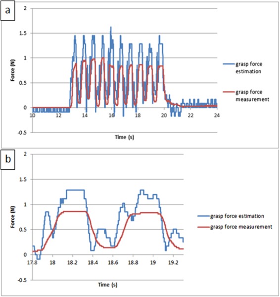
The calibrated experiment result for periodic input on grasp DOF: (a) comparison between the force estimation and the force measurement versus time and (b) two input cycles shown in detail
Similar experiments have been conducted on pitch and yaw DOFs, and the results are similar to those of the grasp DOF. Table 2 shows the calibration coefficients used for each experiment, and Tables 3 and 4 compare the estimation error and time delay between different tests. In the pitch experiment, the time delay is −20 ms, which means the force estimation is ahead of the force measurement; this is reasonable, since the force estimation is obtained from motor current, and force measurement is caused by motor motion. The motor current response is always ahead of motor motion, which leads to the force estimation leading the force measurement.
Table 2.
Calibration coefficients for force estimation on grasp, pitch, and yaw DOFs for the third version prototype
| Tests | Calibration coefficients |
|---|---|
| Grasp test | 1/1.28 |
| Pitch test | 1/1.33 |
| Yaw test | 1/1.64 |
Table 3.
Estimation error in grasp, pitch, and yaw tests (unit: N)
| Long steady input | Short steady input | Periodic input | |
|---|---|---|---|
| Grasp test | 0.24 | 0.46 | 0.49 |
| Pitch test | 0.14 | 0.37 | 0.71 |
| Yaw test | −0.03 | 0.07 | 0.05 |
Table 4.
Time delay in grasp, pitch, and yaw tests (unit: ms)
| Tests | Time delay |
|---|---|
| Grasp test | 0 |
| Pitch test | −20 |
| Yaw test | 0 |
4. Haptic Experiments
To demonstrate the effectiveness of this sensorless force estimation method, two haptic experiments have been implemented with the surgical grasper prototype. The first experiment is to differentiate the stiffness of wood, foam, and sponge materials. Grasping the three materials separately (Fig. 15(a)), the grasp angle and grasp force estimation are recorded, which are shown in Fig. 15(b); the slope represents the material's stiffness. As shown in the figure, due to the dynamic effect, the force estimation signal is noisy, but the stiffness difference can still be clearly identified for these three materials [18].
Fig. 15.
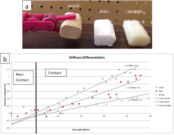
Stiffness differentiation on grasp DOF: (a) experiment setup and (b) result
The second experiment is tumor detection. A stiff object (Ø 7 mm × 3.5 mm cylindrical plastic) is embedded and affixed with glue at the edge of a porcine liver to mimic a tumor, and the surgical grasper is used to grasp the porcine liver along its edge at seven locations (Fig. 16(a)). Each location is grasped three times and the average stiffness is displayed in Fig. 16(b) for all the locations. It is clearly shown that the location with the embedded tumor has higher stiffness compared with the other locations. Compared with the tests in Ref. [18], this tumor detection experiment is a more clinically representative task.
Fig. 16.
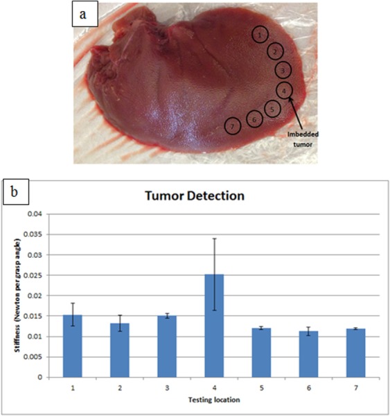
Tumor detection: (a) porcine liver with tumor imbedded and (b) stiffness mapping along the edge of the liver
5. Discussion and Conclusions
This paper presents a sensorless solution to estimate tool–tissue interaction force and validates it on a 3-DOF robotic surgical grasper prototype. The testing results demonstrate that with this method the tool–tissue interaction forces on grasp, pitch, and yaw DOFs can be obtained with acceptable accuracy and latency. This solution makes it possible to equip existing surgical systems with a haptic interface that requires no sensors; this will simplify the surgical tool hardware structure, and also enable the haptic interface to be compatible with existing sterilization technology and surgical procedures.
According to the experiment results, there are three issues remaining to be solved. First, the force estimation in this paper ignores the dynamic effects, which is not a valid assumption at the beginning of force loading, and this causes inflation of the estimation error; exact modeling and compensation is necessary to eliminate this dynamic effect. Second, due to the low strength of 3D-printed plastic components and the low stiffness of the polymeric cable used in the prototypes, the operation force tested to date is only about 2 N; however, literature shows that robotic surgical tools may require larger forces, ranging from 2 N to 40 N for different tools [24,25]; cast or machined metal components and stainless steel cable would enable testing larger forces consistent with clinical needs. Third, the robotic instrument should be mounted on a robot arm with an appropriate haptic human interface for performing more complex, clinically representative tasks, allowing the surgeon to explore the mechanical properties of tissue and/or adjust his/her surgical operation to avoid tissue damage. This article presents demonstration of the concept feasibility, and integration of the presented work with these stated future goals is expected to lead to a more mature, clinically relevant robotic surgical platform.
Acknowledgment
The authors gratefully acknowledge support from the U.S. National Institute of Biomedical Imaging and Bioengineering (Award No. 5 R21 EB015017-02).
Contributor Information
Baoliang Zhao, Department of Mechanical , and Materials Engineering, , University of Nebraska-Lincoln, , Lincoln, NE 68588 , e-mail: baoliang.zhao@yahoo.com.
Carl A. Nelson, Department of Mechanical , and Materials Engineering, , University of Nebraska-Lincoln, , Lincoln, NE 68588; Department of Surgery, , University of Nebraska Medical Center, , Omaha, NE 68198 , e-mail: cnelson5@unl.edu
Nomenclature
- d1, d2, d3 =
pulley diameter
- Dg1, Dg2 =
gear diameter
- J1 =
the motor inertia
- J2 =
the combined inertia of rotational components
- L1, L2, L3, L4 =
center distance between pulleys
- N2/N1 =
the gear ratio
- T =
the total motor torque
- Tf =
the motor torque to overcome friction
- TF =
the motor torque to balance the tool tip interaction forces
- α =
the rotation angle of the line that connects the centers of pulley 1 and pulley 2
- β =
the rotation angle of the line that connects the centers of pulley 2 and pulley 3 with respect to the line that connects the centers of pulley 1 and pulley 2
- θ =
the motor displacement
- θ1, θ2 =
the angle between the line that connects the centers of pulleys and the line that connects the center and its tangent point by the cable
References
- [1].Intuitive Surgical, 2015, “ da Vinci Surgery—Minimally Invasive Robotic Surgery With the da Vinci Surgical System,” accessed June 10, 2014, http://www.davincisurgery.com/facts/
- [2]. Okamura, A. M. , 2009, “ Haptic Feedback in Robot-Assisted Minimally Invasive Surgery,” Curr. Opin. Urol., 19(1), pp. 102–107. 10.1097/MOU.0b013e32831a478c [DOI] [PMC free article] [PubMed] [Google Scholar]
- [3]. Puangmali, P. , Althoefer, K. , Seneviratne, L. D. , Murphy, D. , and Dasgupta, P. , 2008, “ State-of-the-Art in Force and Tactile Sensing for Minimally Invasive Surgery,” IEEE Sens. J., 8(4), pp. 371–381. 10.1109/JSEN.2008.917481 [DOI] [Google Scholar]
- [4]. Fischer, G. S. , Akinbiyi, T. , Saha, S. , Zand, J. , Talamini, M. , Marohn, M. , and Taylor, R. , 2006, “ Ischemia and Force Sensing Surgical Instruments for Augmenting Available Surgeon Information,” International Conference on Biomedical Robotics and Biomechatronics (BioRob 2006), Pisa, Italy, Feb. 20–22, pp. 1030–1035. 10.1109/BIOROB.2006.1639227 [DOI] [Google Scholar]
- [5]. Menciassi, A. , Eisinberg, A. , Carrozza, M. C. , and Dario, P. , 2003, “ Force Sensing Microinstrument for Measuring Tissue Properties and Pulse in Microsurgery,” IEEE/ASME Trans. Mechatronics, 8(1), pp. 10–17. 10.1109/TMECH.2003.809153 [DOI] [Google Scholar]
- [6]. Payne, C. , Tari, H. , Marcus, H. , and Yang, G. , 2014, “ Hand-Held Microsurgical Forceps With Force-Feedback for Micromanipulation,” IEEE International Conference on Robotics and Automation (ICRA), Hong Kong, May 3–June 7, pp. 284–289. 10.1109/ICRA.2014.6906623 [DOI] [Google Scholar]
- [7]. Hammond, F. L. , Smith, M. J. , and Wood, R. J. , 2014, “ Printing Strain Gauges on Surgical Instruments for Force Measurement,” ASME J. Med. Devices, 8(3), p. 030935. 10.1115/1.4027080 [DOI] [Google Scholar]
- [8]. Gafford, G. B. , Kesner, S. , Wood, R. , and Walsh, C. , 2013, “ Force-Sensing Surgical Grasper Enabled by Pop-Up Book MEMS,” IEEE International Conference on Intelligent Robots and Systems (IROS), Tokyo, Nov. 3–7, pp. 2552–2558. 10.1109/IROS.2013.6696716 [DOI] [Google Scholar]
- [9]. Seibold, U. , Kubler, B. , and Hirzinger, G. , 2005, “ Prototype of Instrument for Minimally Invasive Surgery With 6-Axis Force Sensing Capability,” IEEE International Conference on Robotics and Automation (ICRA 2005), Barcelona, Spain, Apr. 18–22, pp. 18–22. 10.1109/ROBOT.2005.1570167 [DOI] [Google Scholar]
- [10]. Kubler, B. , Seibold, U. , and Hirzinger, G. , 2005, “ Development of Actuated and Sensor Integrated Forceps for Minimally Invasive Robotic Surgery,” Int. J. Med. Rob. Comput. Assisted Surg., 1(3), pp. 96–107. 10.1002/rcs.33 [DOI] [PubMed] [Google Scholar]
- [11]. Gray, B. L. , and Fearing, R. S. , 1996, “ A Surface Micromachined Microtactile Sensor Array,” IEEE International Conference on Robotics and Automation (ICRA), Minneapolis, MN, Apr. 22–28, pp. 1–6. 10.1109/ROBOT.1996.503564 [DOI] [Google Scholar]
- [12]. Sokhanvar, S. , Packirisamy, M. , and Dargahi, J. , 2007, “ A Multifunctional PVDF-Based Tactile Sensor for Minimally Invasive Surgery,” Smart Mater. Struct., 16(4), pp. 989–998. 10.1088/0964-1726/16/4/006 [DOI] [Google Scholar]
- [13]. Fetter, E. , Biehl, M. , and Meyer, J. , 1996, “ Vibrotactile Palpation Instrument for Use in Minimally Invasive Surgery,” 18th Annual International IEEE Engineering in Medicine and Biology Society International Conference (IEMBS), Amsterdam, Oct. 31–Nov. 3, pp. 179–180. 10.1109/IEMBS.1996.656905 [DOI] [Google Scholar]
- [14]. Peirs, J. , Clijnen, J. , Reynaerts, D. , Brussel, H. V. , Herijgers, P. , Corteville, B. , and Boone, S. , 2004, “ A Micro Optical Force Sensor for Force Feedback During Minimally Invasive Robotic Surgery,” Sens. Actuators, A, 115, pp. 447–455. 10.1016/j.sna.2004.04.057 [DOI] [Google Scholar]
- [15]. Li, X. , 2001, “ Real-Time Prediction of Work Piece Errors for a CNC Turning Center, Part 3. Cutting Force Estimation Using Current Sensors,” Int. J. Adv. Manuf. Technol., 17(9), pp. 659–664. 10.1007/s001700170130 [DOI] [Google Scholar]
- [16]. Jeong, Y. H. , and Cho, D. W. , 2002, “ Estimating Cutting Force From Rotating and Stationary Feed Motor Currents on a Milling Machine,” Int. J. Mach. Tools Manuf., 42(14), pp. 1559–1566. 10.1016/S0890-6955(02)00082-2 [DOI] [Google Scholar]
- [17]. Tholey, G. , Pillarisetti, A. , Green, W. , and Desai, J. P. , 2004, “ Design, Development, and Testing of an Automated Laparoscopic Grasper With 3-D Force Measurement Capability,” International Symposium on Medical Simulation (ISMS 2004), Cambridge, MA, June 17–18, pp. 38–48. 10.1007/978-3-540-25968-8_5 [DOI] [Google Scholar]
- [18]. Zhao, B. , and Nelson, C. , 2015, “ Sensorless Force Sensing for Minimally Invasive Surgery,” ASME J. Med. Devices, 9(4), p. 041012. 10.1115/1.4031282 [DOI] [PMC free article] [PubMed] [Google Scholar]
- [19]. Zhao, B. , and Nelson, C. , 2013, “ Decoupled Cable-Driven Grasper Design Based on Planetary Gear Theory,” ASME J. Med. Devices, 7(2), p. 020918. 10.1115/1.4024329 [DOI] [Google Scholar]
- [20]. Nelson, C. , 2013, A Primer on Engineering Design of Biomedical Devices, Lulu.com, Raleigh, NC, Chap. 8. [Google Scholar]
- [21]. Zhao, B. , and Nelson, C. , 2015, “ Sensorless Force Estimation for a 3-DOF Motorized Surgical Grasper,” Design of Medical Devices Conference, Minneapolis, MN, Apr. 13–16, Paper No. DMD 2015–8654. [Google Scholar]
- [22]. Zhao, B. , and Nelson, C. , 2015, “ Tool-Tissue Forces Estimation for a 3-DOF Robotic Surgical Tool,” ASME Paper No. DETC 2015–46344. 10.1115/DETC2015-46344 [DOI]
- [23]. Bhagat, N. A. , 2011, “ Sensing and Cancellation of Tremors in Surgeon's Hands During Microsurgery,” M.S. thesis, Indian Institute of Technology Bombay, India. [Google Scholar]
- [24]. Markvicka, E. J. , 2014, “ Design and Development of a Miniature In Vivo Surgical Robot With Distributed Motor Control for Laparoscopic Single-Site Surgery,” M.S. thesis, University of Nebraska–Lincoln, Lincoln, NE: http://digitalcommons.unl.edu/mechengdiss/75/ [Google Scholar]
- [25]. Mucksavage, P. , Kerbl, D. , Pick, D. , Lee, J. , McDougall, E. , and Louie, M. , 2011, “ Differences in Grip Forces Among Various Robotic Instruments and da Vinci Surgical Platforms,” J. Endourol., 25(3), pp. 523–528. 10.1089/end.2010.0306 [DOI] [PubMed] [Google Scholar]


