Abstract
RF coil operation at the ultrahigh field of 7T is fraught with technical challenges that limit the advancement of novel human in vivo applications at 7T. In this work, a hybrid technique combining a microstrip transmission line and a lumped-element L-C loop coil to form a double-nuclear RF coil for proton magnetic resonance imaging and carbon magnetic resonance spectroscopy at 7T was proposed and investigated. Network analysis revealed a high Q-factor and excellent decoupling between the coils. Proton images and localized carbon spectra were acquired with high sensitivity. The successful testing of this novel double-nuclear coil demonstrates the feasibility of this hybrid design for double-nuclear MR imaging and spectroscopy studies at the ultrahigh field of 7T.
Keywords: 7 Tesla, ultrahigh field magnetic resonance imaging (MRI), ultrahigh field magnetic resonance spectroscopy (MRS), microstrip transmission line (MTL) resonator, radio-frequency (RF) coil, surface coil, lumped-element L-C loop coil
Introduction
Double-nuclear MR imaging and spectroscopy is useful for attaining morphological and metabolic information in living systems [1-3]. Obtaining magnetic resonance data at ultra-high magnetic field strengths, e.g., 7T, provides higher signal-to-noise (SNR) and greater spatial and spectral resolution than what can be achieved at lower field strengths [4-16]. Nuclear magnetic resonance (NMR) techniques require RF coils sensitive and efficient enough to acquire the minuscule signals after excitation. As magnetic field strength increases, the nuclear precession frequency, i.e. the frequency of MR signals, increases as well [17,18]. Radiation losses increase with higher resonant frequencies, as does the interaction between the coil and the sample [6,11,19,20]. In a double-tuned RF coil configuration, electromagnetic coupling between different nuclear channels may also become problematic. At high and ultrahigh magnetic fields, this coupling issue ultimately leads to diminished MR signal detection efficiency, particularly for non-proton nuclear channels [21-24].
Several design methods have been proposed to address this problem and to gain better performance in double-nuclear MR acquisitions [3,21-23,25-37]. In this work, we design and test a simple coil configuration for double nuclear 1H imaging and 13C MR spectroscopy at the ultrahigh field of 7T. The design method is based on a hybrid technique using microstrip transmission line resonators [11,20,38-42] for the 1H channel and regular lumped-element L-C loop resonators for 13C. Our design takes advantage of the fact that microstrip transmission lines (MTLs) generate magnetic fields that are perpendicular to that of a loop coil when the strip conductor and wire loop lie on the same plane. This coil layout theoretically provides intrinsic electromagnetic decoupling between the two nuclear channels. Standard RF bench test and MR imaging experiments have been performed to validate the proposed double-tuned coil design method for both the proton channel and the 13C channel.
Methods
Coil Design
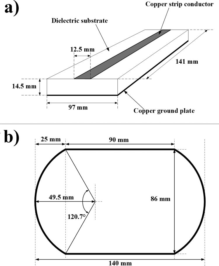
The double-nuclear coil system was comprised of two individual surface coils. A symmetric MTL surface coil was designed for hydrogen MRI at 7T (Figure 1a). Adhesive-backed copper tape was used as the strip conductor (12.5 mm × 141 mm × 36 μm) and the ground plate (97 mm × 141 mm × 36 μm) on a PTFE substrate (97 mm × 260 mm × 14.5 mm). The additional length of the PTFE substrate was used as a platform to secure the coaxial cable connections. Fixed and variable capacitors were used to adjust the resonant frequency of the MTL and to minimize reactance and radiative losses through impedance matching. Tuning capacitors were arranged in a symmetric configuration to maintain a symmetric field distribution along the coil. Matching capacitance was split into two capacitors allowing for electric balancing.
Figure 1.
Diagrams of each RF resonator. a) Microstrip transmission line resonator tuned to the proton precession frequency of 298 MHz. PTFE was used as the dielectric substrate. b) Wire-loop resonator tuned to the carbon-13 precession frequency of 75 MHz. The rounded rectangular shape allowed a larger field of view with less wire than a rectangular coil.
A single-turn, segmented, wire-loop surface coil was created for 13C spectroscopy at 7T (Figure 1b). Round copper wire (18 AWG, 1.0 mm diameter) was shaped into a rounded-rectangular coil and recessed into the PTFE dielectric substrate by 3 mm. Tuning capacitors were placed symmetrically between the segments of the coil. The segmentation of the wire loop coil reduces the effective electrical length of the wire, providing a more homogenous RF field.
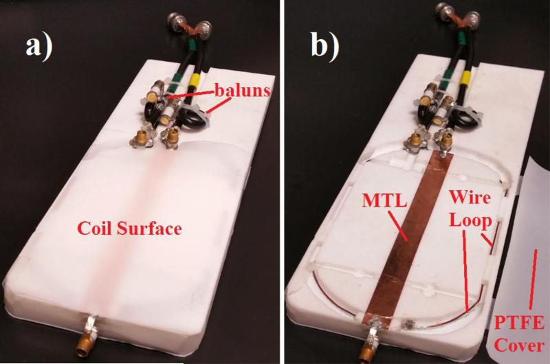
In both coils, single-loop trapping baluns were used to reduce common mode effects. Each balun was tuned to the frequency of the connected coil via a variable capacitor. Figure 2 shows the complete coil system with and without the protective PTFE cover sheet (0.3 mm thickness).
Figure 2.
Images of constructed double-nuclear coil system. a) Coil system with PTFE cover sheet over the resonators. b) Coil system with the PTFE cover sheet moved aside. The wire coil is 3 mm below the plane of the strip conductor and secured with plastic zip-ties.
Bench Tests
Frequency tuning and impedance matching were performed using a network analyzer (Agilent Technologies, Model E5061A). Bench tests consisted of obtaining reflection and transmission coefficients (S11 and S21, respectively) in the unloaded condition.
The S11 measurement tests the reflection of RF power sent by the analyzer to the coil, providing information of the energy absorbed by the coil (and the sample) though displaying the energy that has reflected back to the analyzer. The reflection coefficient is used as a measure of coil impedance matching in this study. The transmission coefficient S21 was used to measure the electromagnetic coupling between the two coils.
These measurements were then used to calculate the coil efficiency (Q-factor). In this study, Quality factor is defined as
| (1) |
where f0 is the frequency of the coil resonance, (f2-f1) is the 3dB bandwidth of the S11 spectrum.
Measurements of resonant frequency shift due to coil loading of small and light samples were obtained by tuning each coil with the phantoms placed on the top surface of the coil assembly, then subsequently removing the phantoms and observing the shift in peak resonant frequency. Any significant shifts would indicate capacitive coupling between the coil and the phantom.
Scanning Parameters
MR data were obtained using the GE 7T whole-body scanner (GE Healthcare, Model MR950). Two phantoms were imaged: a plastic syringe (30 ml) containing 23 ml of ethylene glycol and a plastic syringe (1 ml) containing 0.95 ml of urea. A 2D gradient-recalled echo (GRE) pulse sequence was used for proton imaging (TR = 8.1 ms, TE = 2.8 ms, NEX = 3, α = 30°, spatial resolution = 0.31 mm × 0.31 mm × 3 mm, matrix size = 256 × 256).
Ethylene glycol spectroscopic data were acquired using a 2D free-induction decay chemical shift imaging (FID-CSI) pulse sequence (TR = 1000 ms, TE = 2.86 ms, NEX = 8, α = 90°, reference chemical shift = 63.4 ppm, sweep width = 5 kHz, time points = 2048, dwell time = 0.2 ms, spatial resolution = 4 mm × 4 mm × 30 mm, matrix size = 8 × 8).
Urea spectroscopic data were acquired using a 2-D FID-CSI pulse sequence (TR = 1000 ms, TE = 3.27 ms, NEX = 8, α = 90°, reference chemical shift = 174.3 ppm, sweep width = 5 kHz, time points = 2048, dwell time = 0.2 ms, spatial resolution = 2 mm × 2 mm × 5 mm, matrix size = 8 × 8).
Data Processing
AMIDE software [43] was used to visualize the proton DICOM data and to produce 1D sensitivity profiles across each viewing plane. Raw spectroscopic data were reconstructed through the use of the imaging program, SIVIC [44]. A 9 Hz Lorentzian apodization filter was applied to the raw spectroscopic data prior to spatial and spectral Fourier transformation. Analysis was conducted using the absolute values (magnitude only) of the spectra. The expected MRS peak for ethylene glycol sample was 63.4 ppm, while the expected peak for urea sample was 174.3 ppm.
Results
Bench Tests
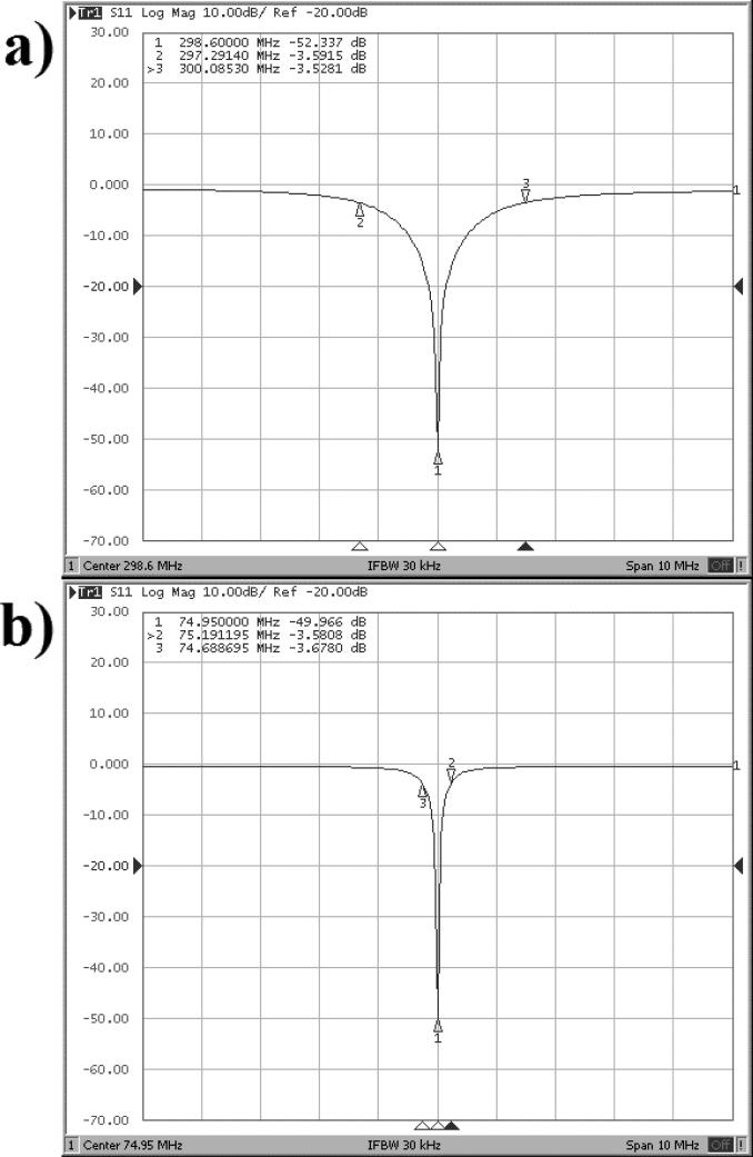
The MTL coil performed well as measured by the network analyzer parameter S11. Figure 3 presents the reflection coefficient graphs for the MTL coil and the wire-loop coil in the unloaded condition. Once the MTL was tuned and properly matched, the coil showed excellent energy deposition with a loss of −52.34 dB at the resonant frequency of 298.60 MHz. The loop coil also performed well with a loss of −49.97 dB at the resonant frequency of 74.95 MHz. Coil efficiency in the unloaded condition as measured by the Q-factor was high with values above 200 for both coils. The results are summarized in Table 1.
Figure 3.
Reflection coefficient graphs of each coil in the coil unloaded condition. a) Results from the hydrogen microstrip coil. b) Results from the carbon wire-loop coil. The scale in both graphs along the x-axis is 1 MHz per square, and along the y-axis each box represents 10 dB per square.
Table 1.
Electrical characteristics of microstrip transmission line coil (1H) and wire loop coil (13C).
| Coil | Condition | f (MHz) | BW (MHz) | S11 (dB) | S21 (dB) | Q |
|---|---|---|---|---|---|---|
| 1H MTL | Empty | 298.60 | 2.79 | −52.34 | −25.66 | 213.75 |
| 13C Loop | w/ 30mL Ethylene glycol | 74.95 | 0.5 | −49.97 | −17.80 | 298.31 |
f = Resonant Frequency, BW = Bandwidth, S11 = Reflection Coefficient, S21 = Transmission Coefficient, Q = Quality Factor.
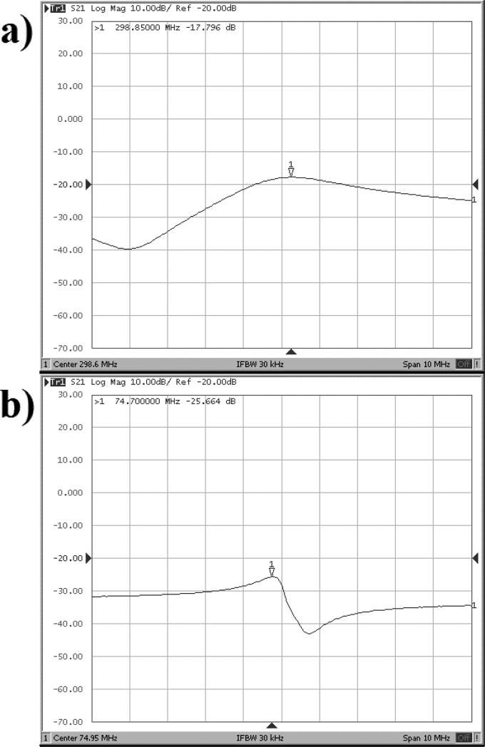
Coil decoupling was measured through the S21 parameter. Figure 4 displays the transmission coefficient data. Each coil showed a moderately high level of decoupling, with the MTL receiving just −25.66 dB of signal from the loop coil, and the loop coil showing only −17.80 dB of the MTL signal.
Figure 4.
Transmission coefficient graphs of each coil in the coil unloaded condition. a) Results from the hydrogen microstrip coil. b) Results from the carbon wire-loop coil. The scale in both graphs along the x-axis is 1 MHz per square, and along the y-axis each box represents 10 dB per square.
The experiment of coil frequency shift with and without small samples (30mL and 0.95mL) was performed independently of the S11 and S21 measurements above. Results are summarized in Table 2. The MTL experienced a slight shift from the tuned frequency of 298.45 MHz with the phantoms on the coil. Upon removal, the resonant frequency shifted +1.10 MHz. The wire-loop coil exhibited no noticeable frequency shift in resonant frequency between different conditions.
Table 2.
Frequency shifts of microstrip transmission line (1H) and wire loop coil (13C) with the small samples.
| Coil | Condition | f (MHz) | BW (MHz) | S11 (dB) | Q |
|---|---|---|---|---|---|
| 1H MTL | Empty (unloaded) with small samples (30mL Ethylene glycol) Δ | 299.55 | 3.16 | −23.50 | 189.85 |
| 298.45 | 3.44 | −43.77 | 173.66 | ||
| −1.10 | 0.28 | −20.28 | −16.18 | ||
| 13C Loop | Empty (unloaded) with small samples (0.95mL urea) Δ | 74.95 | 0.51 | −42.26 | 292.46 |
| 74.95 | 0.51 | −40.17 | 292.46 | ||
| 0 | 0 | 2.10 | 0 |
Proton Imaging
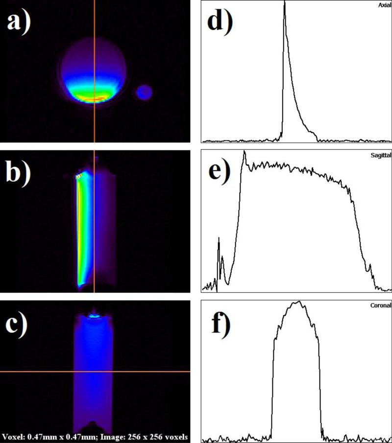
Images of the phantoms were acquired in the axial, coronal, and sagittal planes. Images were then used to generate a 1D sensitivity graph across the mid-line of the largest phantom, the syringe filled with 23 ml of ethylene glycol. Figure 5 shows this phantom in all three dimensions with corresponding sensitivity graphs. To accentuate signal intensity, a color look-up table (CLUT) was applied through the AMIDE imaging program.
Figure 5.
Proton images and line intensity profiles in each plane. A rainbow color lookup table has been used to accentuate signal intensity. (a) Axial view. (b) Sagittal view. (c) Coronal view. (d) Intensity profile across axial view image. Left to right corresponds with bottom to top in a). (e) Intensity profile across sagittal image. Left to right corresponds with top to bottom in b). (f) Intensity profile across coronal image. The line profile is in the same direction as c).
13C Spectroscopy
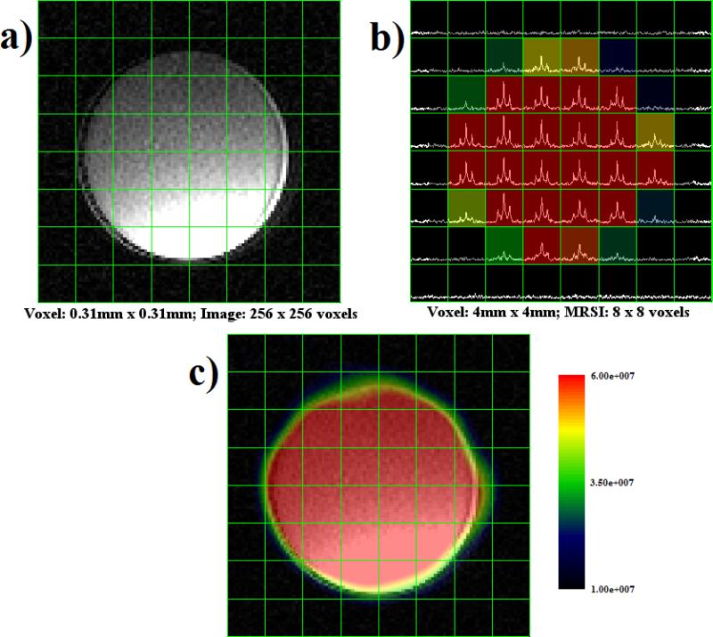
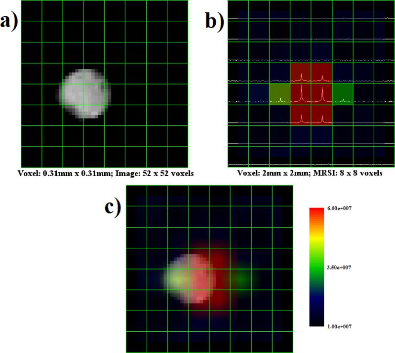
Figure 6a shows an axial view of the ethylene glycol phantom with an 8 × 8 grid overlay while Figure 6b displays the grid overlay with spectra plotted inside each voxel. The ethylene glycol spectroscopic data were spatially smoothed using a sinc kernel in SIVIC to produce the MRS image shown in Figure 6c. These same processing steps were taken with the data from the small urea phantom. Figure 7a presents an axial view of the urea phantom. Figure 7b shows the spectroscopic data for each voxel, and the corresponding interpolated spectral image is shown in Figure 7c.
Figure 6.
Montage of ethylene glycol image and spectroscopic data. (a) Proton MRI with 8 × 8 grid overlay. (b) MRS data presented in each voxel, with peaks corresponding to 13C chemical shift. (c) MRSI generated from spatial and spectral data representing ethylene glycol concentration. The color overlay was spatially smoothed using a sinc kernel in SIVIC.
Figure 7.
Montage of urea image and spectroscopic data. a) Proton MRI with 8 × 8 grid overlay. b) MRS data presented in each voxel, with peaks corresponding to 13C chemical shift. c) MRSI generated from spatial and spectral data representing urea concentration. Note the small spatial shift between image and spectroscopic data. The color overlay was spatially smoothed using a sinc kernel in SIVIC.
Discussion
Overall, the double-nuclear coil system performed well by every measure. Reflection coefficients showed excellent frequency specificity as indicated by the Q-factors, while transmission coefficients revealed excellent decoupling between coils. The overall efficiency of the wire-loop coil operating at much lower frequency was higher than that of the MTL.
The load frequency shift experiment was conducted to assess the amount of coupling between the sample and the coil, also known as parasitic capacitance, due to the reduction of the resonant frequency when a sample is loaded onto the coil [24]. The MTL experienced a small but significant frequency shift of 1.10 MHz. indicating some level of sample coupling. Since the frequency bandwidth of RF pulses is typically on the order of kHz, this amount of coupling requires retuning the coil when it is loaded and connected to the scanner to prevent a large amount of energy from reflecting back to the system, causing damage. The wire-loop coil performed extremely well during this test. There was no noticeable frequency shift in the loop coil between loading conditions. This may be also due to the small and light imaging samples used for this test.
Proton images generated in each plane showed a significant drop in signal intensity as a function of distance from the conduction strip. The sensitivity of the MTL was limited to a few centimeters around the midline of the main conducting strip. Given the geometry of the MTL and the properties of electromagnetic radiation, this sensitivity profile is exactly what was expected as typical microstrip coil behavior [11,20,40]. However, as demonstrated in literature [8], the field penetration of a microstrip coil can be changed by increasing the substrate thickness of the microstrip transmission line resonator.
The carbon spectroscopic reconstructions revealed excellent sensitivity to the relatively miniscule 13C signal. This was particularly evident in the larger of the two phantoms. Throughout the volume of the sample, peak amplitude corresponded directly with the amount of ethylene glycol in a given voxel. The urea spectroscopic data showed a slight shift in spatial location from the proton image. One way to improve this result would be to increase the resolution of the spectroscopic data. This would entail a substantial increase in acquisition time that was unattainable during this experiment.
Given the specific geometry and size of the prototype coil, a potential application of this coil will be the human calf muscle imaging and spectroscopy in investigating muscle fiber orientation, intramyocellular lipids, congenital myasthenic syndromes, and energy metabolism [45-51]. It can be also used for human extremity 13C/1H spectroscopic imaging at the ultrahigh field of 7T.
Conclusion
A simple double-nuclear RF coil using a hybrid method combining microstrip transmission line resonators and lumped-element loop resonators has been developed and investigated for 1H/13C MRI and MRSI at the ultrahigh field of 7T. The prototype of the double-nuclear coil performed well in the aspects of quality factors, imaging coverage, and electromagnetic decoupling between the two nuclear channels, based on bench tests and MRI and MRSI experiments. This design was possible because of the high frequency capability of microstrip resonators and superior decoupling performance resulting from inherently perpendicular fields of the microstrip and the lumped-element loop resonator. This simple and compact double-nuclear coil shows promise for the future where it could be used as array elements in double-tuned RF coil arrays for accelerated imaging and spectroscopic imaging at 7T when appropriate decoupling techniques [52-54] are applied. This could include a planar phased array for human spinal 1H imaging and heteronuclear metabolic imaging, or a cylindrical array for human knee or head double-nuclear MR imaging.
Acknowledgements
It is a pleasure to thank Andrew Leynes, who assisted with the fabrication of the coil system and provided technical assistance when necessary. This work was supported in part by National Institutes of Health (NIH) grants R01EB008699, R21EB020283, R01EB012031, and P41EB013598, and a UCSF Academic Senate Award to XZ.
Footnotes
Publisher's Disclaimer: This is a PDF file of an unedited manuscript that has been accepted for publication. As a service to our customers we are providing this early version of the manuscript. The manuscript will undergo copyediting, typesetting, and review of the resulting proof before it is published in its final citable form. Please note that during the production process errors may be discovered which could affect the content, and all legal disclaimers that apply to the journal pertain.
References
- 1.Bottomley PA, Edelstein WA, Hart HR, Schenck JF, Smith LS. Spatial localization in 31P and 13C NMR spectroscopy in vivo using surface coils. Magn Reson Med. 1984;1(3):410–413. doi: 10.1002/mrm.1910010311. [DOI] [PubMed] [Google Scholar]
- 2.Hardy CJ, Bottomley PA, Rohling KW, Roemer PB. An NMR phased array for human cardiac 31P spectroscopy. Magn Reson Med. 1992;28(1):54–64. doi: 10.1002/mrm.1910280106. [DOI] [PubMed] [Google Scholar]
- 3.Fitzsimmons JR, Beck BL, Brooker HR. Double resonant quadrature birdcage. Magn Reson Med. 1993;30(1):107–114. doi: 10.1002/mrm.1910300116. [DOI] [PubMed] [Google Scholar]
- 4.Ugurbil K, Hu X, Chen W, Zhu XH, Kim SG, Georgopoulos A. Functional mapping in the human brain using high magnetic fields. Philos Trans R Soc Lond B Biol Sci. 1999;354(1387):1195–1213. doi: 10.1098/rstb.1999.0474. [DOI] [PMC free article] [PubMed] [Google Scholar]
- 5.Ugurbil K, Garwood M, Ellermann J, Hendrich K, Hinke R, Hu X, Kim SG, Menon R, Merkle H, Ogawa S, et al. Imaging at high magnetic fields: initial experiences at 4 T. Magn Reson Q. 1993;9(4):259–277. [PubMed] [Google Scholar]
- 6.Vaughan JT, Garwood M, Collins CM, Liu W, DelaBarre L, Adriany G, Andersen P, Merkle H, Goebel R, Smith MB, Ugurbil K. 7T vs. 4T: RF power, homogeneity, and signal-to-noise comparison in head images. Magn Reson Med. 2001;46(1):24–30. doi: 10.1002/mrm.1156. [DOI] [PubMed] [Google Scholar]
- 7.Hoult DI, Chen CN, Sank VJ. The field dependence of NMR imaging. II. Arguments concerning an optimal field strength. Magn Reson Med. 1986;3(5):730–746. doi: 10.1002/mrm.1910030509. [DOI] [PubMed] [Google Scholar]
- 8.Collins CM, Smith MB. Signal-to-noise ratio and absorbed power as functions of main magnetic field strength, and definition of “90 degrees” RF pulse for the head in the birdcage coil. Magn Reson Med. 2001;45(4):684–691. doi: 10.1002/mrm.1091. [DOI] [PubMed] [Google Scholar]
- 9.Yacoub E, Shmuel A, Pfeuffer J, Van De Moortele PF, Adriany G, Andersen P, Vaughan JT, Merkle H, Ugurbil K, Hu X. Imaging brain function in humans at 7 Tesla. Magn Reson Med. 2001;45(4):588–594. doi: 10.1002/mrm.1080. [DOI] [PubMed] [Google Scholar]
- 10.Lei H, Zhu XH, Zhang XL, Ugurbil K, Chen W. In vivo 31P magnetic resonance spectroscopy of human brain at 7 T: an initial experience. Magn Reson Med. 2003;49(2):199–205. doi: 10.1002/mrm.10379. [DOI] [PubMed] [Google Scholar]
- 11.Zhang X, Ugurbil K, Chen W. Microstrip RF surface coil design for extremely highfield MRI and spectroscopy. Magn Reson Med. 2001;46(3):443–450. doi: 10.1002/mrm.1212. [DOI] [PubMed] [Google Scholar]
- 12.Zhao W, Cohen-Adad J, Polimeni JR, Keil B, Guerin B, Setsompop K, Serano P, Mareyam A, Hoecht P, Wald LL. Nineteen-channel receive array and four-channel transmit array coil for cervical spinal cord imaging at 7T. Magn Reson Med. 2014;72(1):291–300. doi: 10.1002/mrm.24911. [DOI] [PMC free article] [PubMed] [Google Scholar]
- 13.Wu B, Wang C, Krug R, Kelley DA, Xu D, Pang Y, Banerjee S, Vigneron DB, Nelson SJ, Majumdar S, Zhang X. 7T human spine imaging arrays with adjustable inductive decoupling. IEEE Trans Biomed Eng. 2010;57(2):397–403. doi: 10.1109/TBME.2009.2030170. [DOI] [PMC free article] [PubMed] [Google Scholar]
- 14.Wu B, Zhang X, Wang C, Li Y, Pang Y, Lu J, Xu D, Majumdar S, Nelson SJ, Vigneron DB. Flexible transceiver array for ultrahigh field human MR imaging. Magn Reson Med. 2012;68(4):1332–1338. doi: 10.1002/mrm.24121. [DOI] [PMC free article] [PubMed] [Google Scholar]
- 15.Thomas BP, Welch EB, Niederhauser BD, Whetsell WO, Jr., Anderson AW, Gore JC, Avison MJ, Creasy JL. High-resolution 7T MRI of the human hippocampus in vivo. J Magn Reson Imaging. 2008;28(5):1266–1272. doi: 10.1002/jmri.21576. [DOI] [PMC free article] [PubMed] [Google Scholar]
- 16.Zhang X, Zhu XH, Chen W. Higher-order harmonic transmission-line RF coil design for MR applications. Magn Reson Med. 2005;53(5):1234–1239. doi: 10.1002/mrm.20462. [DOI] [PubMed] [Google Scholar]
- 17.Bernstein MA, King KF, Zhou XJ. Handbook of MRI pulse sequences. Elsevier Academic Press; 2004. [Google Scholar]
- 18.Chen CN, Hoult DI. Biomedical magnetic resonance technology. Adam Hilger; New York: 1989. [Google Scholar]
- 19.Wen H, Chesnick AS, Balaban RS. The design and test of a new volume coil for high field imaging. Magn Reson Med. 1994;32(4):492–498. doi: 10.1002/mrm.1910320411. [DOI] [PMC free article] [PubMed] [Google Scholar]
- 20.Adriany G, Van de Moortele PF, Wiesinger F, Moeller S, Strupp JP, Andersen P, Snyder C, Zhang X, Chen W, Pruessmann KP, Boesiger P, Vaughan T, Ugurbil K. Transmit and receive transmission line arrays for 7 Tesla parallel imaging. Magn Reson Med. 2005;53(2):434–445. doi: 10.1002/mrm.20321. [DOI] [PubMed] [Google Scholar]
- 21.Pang Y, Xie Z, Xu D, Kelley DA, Nelson SJ, Vigneron DB, Zhang X. A dual-tuned quadrature volume coil with mixed lambda/2 and lambda/4 microstrip resonators for multinuclear MRSI at 7 T. Magn Reson Imaging. 2012;30(2):290–298. doi: 10.1016/j.mri.2011.09.022. [DOI] [PMC free article] [PubMed] [Google Scholar]
- 22.Wang C, Li Y, Wu B, Xu D, Nelson SJ, Vigneron DB, Zhang X. A practical multinuclear transceiver volume coil for in vivo MRI/MRS at 7 T. Magn Reson Imaging. 2012;30(1):78–84. doi: 10.1016/j.mri.2011.08.007. [DOI] [PMC free article] [PubMed] [Google Scholar]
- 23.Pang Y, Zhang X, Xie Z, Wang C, Vigneron DB. Common-mode differential-mode (CMDM) method for double-nuclear MR signal excitation and reception at ultrahigh fields. IEEE Trans Med Imaging. 2011;30(11):1965–1973. doi: 10.1109/TMI.2011.2160192. [DOI] [PMC free article] [PubMed] [Google Scholar]
- 24.Mispelter JI, Lupu M, Briguet A. NMR probeheads for biophysical and biomedical experiments : theoretical principles & practical guidelines. Imperial College Press; London: 2006. [Google Scholar]
- 25.Alecci M, Romanzetti S, Kaffanke J, Celik A, Wegener HP, Shah NJ. Practical design of a 4 Tesla double-tuned RF surface coil for interleaved 1H and 23Na MRI of rat brain. J Magn Reson. 2006;181(2):203–211. doi: 10.1016/j.jmr.2006.04.011. [DOI] [PubMed] [Google Scholar]
- 26.Amari S, Ulug AM, Bornemann J, van Zijl PC, Barker PB. Multiple tuning of birdcage resonators. Magn Reson Med. 1997;37(2):243–251. doi: 10.1002/mrm.1910370217. [DOI] [PubMed] [Google Scholar]
- 27.Avdievich NI, Hetherington HP. 4 T Actively detuneable double-tuned 1H/31P head volume coil and four-channel 31P phased array for human brain spectroscopy. J Magn Reson. 2007;186(2):341–346. doi: 10.1016/j.jmr.2007.03.001. [DOI] [PMC free article] [PubMed] [Google Scholar]
- 28.Doty FD, Entzminger G, Jr., Hauck CD, Staab JP. Practical aspects of birdcage coils. J Magn Reson. 1999;138(1):144–154. doi: 10.1006/jmre.1998.1703. [DOI] [PubMed] [Google Scholar]
- 29.Hudson AM, Kockenberger W, Bowtell RW. Dual resonant birdcage coils for 1H detected 13C microscopic imaging at 11.7 T. MAGMA. 2000;10(2):61–68. doi: 10.1016/s1352-8661(00)00068-5. [DOI] [PubMed] [Google Scholar]
- 30.Isaac G, Schnall MD, Lenkinski RE, Vogele K. A Design for a Double-Tuned Birdcage Coil for Use in an Integrated MRI/MRS Examination. Journal of Magnetic Resonance. 1990;89(1):41–50. [Google Scholar]
- 31.Joseph PM, Lu D. A technique for double resonant operation of birdcage imaging coils. IEEE Trans Med Imaging. 1989;8(3):286–294. doi: 10.1109/42.34719. [DOI] [PubMed] [Google Scholar]
- 32.Matson GB, Vermathen P, Hill TC. A practical double-tuned 1H/31P quadrature birdcage headcoil optimized for 31P operation. Magn Reson Med. 1999;42(1):173–182. doi: 10.1002/(sici)1522-2594(199907)42:1<173::aid-mrm23>3.0.co;2-o. [DOI] [PubMed] [Google Scholar]
- 33.Murphyboesch J, Srinivasan R, Carvajal L, Brown TR. 2 Configurations of the 4-Ring Birdcage Coil for H-1 Imaging and H-1-Decoupled P-31 Spectroscopy of the Human Head. J Magn Reson Ser B. 1994;103(2):103–114. doi: 10.1006/jmrb.1994.1017. [DOI] [PubMed] [Google Scholar]
- 34.Shen GX, Wu JF, Boada FE, Thulborn KR. Experimentally verified, theoretical design of dual-tuned, low-pass birdcage radiofrequency resonators for magnetic resonance imaging and magnetic resonance spectroscopy of human brain at 3.0 Tesla. Magn Reson Med. 1999;41(2):268–275. doi: 10.1002/(sici)1522-2594(199902)41:2<268::aid-mrm9>3.0.co;2-g. [DOI] [PubMed] [Google Scholar]
- 35.Zhang X, Zhu X, Qiao H, Liu H, Vaughan T, Ugurbil K, Chen W. Proceedings of the 11th Annual Meeting of the International Society of Magnetic Resonance in Medicine. Toronto, ON, Canada: 2003. A circular-polarized double-tuned (31P and 1H) TEM coil for human head MRI/MRS at 7T; p. 423. [Google Scholar]
- 36.Rath AR. Design and Performance of a Double-Tuned Bird-Cage Coil. Journal of Magnetic Resonance. 1990;86(3):488–495. [Google Scholar]
- 37.Tomanek B, Volotovskyy V, Gruwel MLH, McKenzie E, King SB. Double-frequency birdcage volume coils for 4.7T and 7T. Concept Magn Reson B. 2005;26B(1):16–22. [Google Scholar]
- 38.Zhang X, Ugurbil K, Chen W. A microstrip transmission line volume coil for human head MR imaging at 4T. J Magn Reson. 2003;161(2):242–251. doi: 10.1016/s1090-7807(03)00004-1. [DOI] [PubMed] [Google Scholar]
- 39.Zhang X, Ugurbil K, Chen W. Method and apparatus for magnetic resonance imaging and spectroscopy using microstrip transmission line coils, Regents of the University of Minnesota, assignee. 2006 US Patent 7023209 10/09/2001.
- 40.Zhang X, Ugurbil K, Sainati R, Chen W. An inverted-microstrip resonator for human head proton MR imaging at 7 tesla. IEEE Trans Biomed Eng. 2005;52(3):495–504. doi: 10.1109/TBME.2004.842968. [DOI] [PubMed] [Google Scholar]
- 41.Bahl IJ, Trivedi DK. A designer's guide to microstrip line. Microwaves. 1977;16(May):174–182. [Google Scholar]
- 42.Wheeler H. Transmission-line properties of a strip on a dielectric sheet on a plane. IEEE Trans on Microwave Theory & Techniques. 1977;25(8):631–647. [Google Scholar]
- 43.Loening AM, Gambhir SS. AMIDE: a free software tool for multimodality medical image analysis. Mol Imaging. 2003;2(3):131–137. doi: 10.1162/15353500200303133. [DOI] [PubMed] [Google Scholar]
- 44.Crane JC, Olson MP, Nelson SJ. SIVIC: Open-Source, Standards-Based Software for DICOM MR Spectroscopy Workflows. Int J Biomed Imaging. 2013;2013:169526. doi: 10.1155/2013/169526. [DOI] [PMC free article] [PubMed] [Google Scholar]
- 45.Vermathen P, Boesch C, Kreis R. Mapping fiber orientation in human muscle by proton MR spectroscopic imaging. Magn Reson Med. 2003;49(3):424–432. doi: 10.1002/mrm.10396. [DOI] [PubMed] [Google Scholar]
- 46.Vermathen P, Kreis R, Boesch C. Distribution of intramyocellular lipids in human calf muscles as determined by MR spectroscopic imaging. Magn Reson Med. 2004;51(2):253–262. doi: 10.1002/mrm.10721. [DOI] [PubMed] [Google Scholar]
- 47.Dong Z, Hwang JH. Lipid signal extraction by SLIM: application to 1H MR spectroscopic imaging of human calf muscles. Magn Reson Med. 2006;55(6):1447–1453. doi: 10.1002/mrm.20895. [DOI] [PubMed] [Google Scholar]
- 48.Newcomer BR, Lawrence JC, Buchthal S, den Hollander JA. High-resolution chemical shift imaging for the assessment of intramuscular lipids. Magn Reson Med. 2007;57(5):848–858. doi: 10.1002/mrm.21209. [DOI] [PubMed] [Google Scholar]
- 49.Kan HE, Klomp DW, Wohlgemuth M, van Loosbroek-Wagemans I, van Engelen BG, Padberg GW, Heerschap A. Only fat infiltrated muscles in resting lower leg of FSHD patients show disturbed energy metabolism. NMR Biomed. 2010;23(6):563–568. doi: 10.1002/nbm.1494. [DOI] [PubMed] [Google Scholar]
- 50.Dong Z, Zhang Y, Liu F, Duan Y, Kangarlu A, Peterson BS. Improving the spectral resolution and spectral fitting of (1) H MRSI data from human calf muscle by the SPREAD technique. NMR Biomed. 2014;27(11):1325–1332. doi: 10.1002/nbm.3193. [DOI] [PubMed] [Google Scholar]
- 51.Finlayson S, Morrow JM, Rodriguez Cruz PM, Sinclair CD, Fischmann A, Thornton JS, Knight S, Norbury R, White M, Al-Hajjar M, Carboni N, Jayawant S, Robb SA, Yousry TA, Beeson D, Palace J. Muscle MRI in congenital myasthenic syndromes. Muscle Nerve. 2016 doi: 10.1002/mus.25035. [DOI] [PMC free article] [PubMed] [Google Scholar]
- 52.Li Y, Xie Z, Pang Y, Vigneron D, Zhang X. ICE decoupling technique for RF coil array designs. Med Phys. 2011;38(7):4086–4093. doi: 10.1118/1.3598112. [DOI] [PMC free article] [PubMed] [Google Scholar]
- 53.Yan X, Zhang X, Wei L, Xue R. Magnetic wall decoupling method for monopole coil array in ultrahigh field MRI: a feasibility test. Quant Imaging Med Surg. 2014;4(2):79–86. doi: 10.3978/j.issn.2223-4292.2014.04.10. [DOI] [PMC free article] [PubMed] [Google Scholar]
- 54.Yan X, Zhang X, Feng B, Ma C, Wei L, Xue R. 7T transmit/receive arrays using ICE decoupling for human head MR imaging. IEEE Trans Med Imaging. 2014;33(9):1781–1787. doi: 10.1109/TMI.2014.2313879. [DOI] [PubMed] [Google Scholar]


