Abstract
Robotic needle steering systems have the potential to improve percutaneous interventions such as radiofrequency ablation of liver tumors, but steering techniques described to date have not achieved sufficiently small radius of curvature in biological tissue to be relevant to this application. In this work, the impact of tip geometry on steerable needle curvature is examined. Finite-element simulations and experiments with bent-tip needles in ex vivo liver tissue demonstrate that selection of tip length and angle can greatly improve curvature, with radius of curvature below 5 cm in liver tissue possible through judicious selection of these parameters. Motivated by the results of this analysis, a new articulated-tip steerable needle is described, in which a distal section is actively switched by a robotic system between a straight tip (resulting in a straight path) and a bent tip (resulting in a curved path). This approach allows the tip length and angle to be increased, while the straight configuration allows the needle tip to still pass through an introducer sheath and rotate inside the body. Validation testing in liver tissue shows that the new articulated-tip steerable needle achieves smaller radius of curvature compared to bent-tip needles described in previous work. Steerable needles with optimized tip parameters, which can generate tight curves in liver tissue, increase the clinical relevance of needle steering to percutaneous interventions.
Keywords: Robotic needle steering, flexible needles, medical robots, percutaneous interventions
I. Introduction
Robotic needle steering refers to the use of a robotic system to insert flexible needles along curved paths through tissue. In a variety of percutaneous interventions— including our target application, radiofrequency ablation (RFA) of liver tumors—the ability to insert needles along controlled curved paths would benefit patients in three possible ways. Specifically, robotic needle steering may allow clinicians to (1) correct for errors during insertion and reach a target with superior accuracy compared to manual insertion, (2) steer around obstacles to previously unreachable targets, and (3) reach multiple targets from a single insertion site, thus reducing trauma to the patient.
A number of methods have been described for steering needles through tissue. A recent review is given in [1]. DiMaio and Salcudean [2] and Glozman and Shoham [3] used lateral robotic manipulation of the needle base during insertion to steer the needle. Mallapragada et al. [4] and Torabi et al. [5] used robotic manipulation of simulated tissues around a needle during insertion to steer the needle. Okazawa et al. [6] used a precurved stylet that could be rotated and translated relative to a straight needle shaft to steer a manually inserted needle device. The same concept of overlapping pre-curved sections has been applied in multiple stages in the active cannula robots described by Sears and Dupont [7] and Webster et al. [8]. Kratchman et al. [9] described tendon actuation systems designed to steer flexible needle shafts in solid tissue. Ayvali et al. [10], Datla et al. [11], and Ryu et al. [12] have described using shape memory alloy (SMA) actuators to articulate needle sections, with the latter system using optically actuated SMA tendons to allow compatibility with MRI systems. Ko and Rodriguez y Baena [13] have described a biologically inspired needle that steers by adjusting the relative offset between parallel sections. In our previous work we have used bent-tip steerable needles: flexible needle shafts with bent distal sections as shown in Fig. 1. These needles naturally steer along curved paths during insertion as a result of the net lateral force acting at the distal end of the needles [14]. A duty-cycle control approach, first proposed by Minhas et al. [15], allows curvature to be varied by alternating periods of needle rotation. A bent-tip needle with a passive flexure was introduced by Swaney et al. [16] to reduce tissue damage caused by the bent tip during rotation. Similar flexible needles with bevel tips [17], [18] and curved distal sections [19] have also been described. A tendon-actuated bent-tip steerable needle was described by van de Berg et al. [20]. This design incorporates a two degree-of-freedom ball and socket joint with a conical tip to achieve 3D steering, and uses an integrated shape sensor for closed-loop control.
Fig. 1.
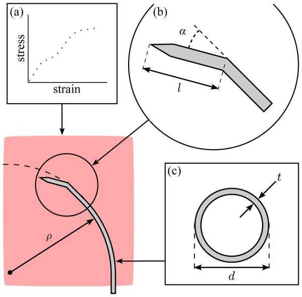
Factors impacting the radius of curvature ρ of bent-tip steerable needles in liver tissue include (a) mechanical properties of the tissue (modeled as a hyperelastic solid), (b) tip geometry (defined by length l and angle α), and (c) needle material and cross section (defined by diameter d and wall thickness t). In this paper, we exclusively consider the impact of tip length l and tip angle α.
Experimental validation of the different needle steering techniques has been performed in artificial tissue simulants [2], [4], [6], [10]–[13], [16], [20]–[22], ex vivo biological tissue samples [3], [16], [21]–[24], and in one live canine model [24]. Compared to other needle steering techniques [2], [4], [6], [12], [13], bent-tip steerable needles have shown the most promising performance results (i.e., have followed the most tightly curved paths) in both artificial tissue simulants and biological tissues. Bent-tip steerable needles generally perform better in artificial tissue simulants than in biological tissues, presumably because artificial tissue simulants are stiffer and more homogeneous. Experimental studies testing bent-tip steerable needles in artificial tissue simulants have reported radius-of-curvature values of 67 mm [21], 121 mm [16], and 128 mm [22]. Experimental studies testing bent-tip steerable needles in ex vivo biological tissues have reported radius-of-curvature values of 41.7 mm [25], 51.4 mm [26], 137 mm [21], 176 mm [16], 200 mm [24], and 400 mm [22]. In the only reported in vivo test, bent-tip steerable needles followed curved paths with radii of curvature from 104 mm to 143 mm in canine kidney and liver tissue [24].
The requirement for needle curvature is specific to the clinical application under consideration. It depends on the geometry of the target anatomy, and the desired use case for needle steering; in other words, whether needle steering will be used to correct for small errors in straight-line targeting, or to reach widely divergent targets or targets obscured by obstacles. Although existing techniques may be useful for small error corrections, our goal is to use needle steering in percutaneous RFA of liver tumors to reach multiple targets throughout the liver from a single wound to the liver capsule, thus reducing the risk of hemorrhage, and to reach targets high in the liver dome and targets blocked by large-diameter vasculature, thus treating patients who would otherwise be excluded. Based on the curvature results reported to date, it is reasonable to question whether existing steerable needles are capable of creating curved needle paths in biological tissues that are clinically relevant to our application.
To set a design requirement for needle curvature in our application, we performed a procedure-specific workspace analysis [27]. In that study, we processed contrast-enhanced CT data to define the geometry of the liver capsule and large-diameter hepatic and portal veins. We discretized the liver volume, and used a path-planning algorithm to determine the fraction of the liver that could be reached from clinically realistic entry vectors as a function of the minimum radius of curvature of the needle path. The results showed that a minimum radius of curvature below 50 mm is necessary to reach the majority of the liver (80 percent of the total volume).
Although we previously reported radius-of-curvature values close to or below 50 mm in ex vivo liver tissue [25], [26], solid Nitinol wires approximately 0.5 mm in diameter were used in those tests. These solid wires would be unable to deliver payloads such as contrast fluid, ethyl alcohol, or ablation leads. As we work towards early-stage clinical tests in the liver, steerable needle design requirements are increasingly driven by practical issues, such as the need to deliver a payload, or the need to pass through a rigid introducer sheath accessing the liver itself through layers of skin and fat. In this paper our goal was to develop a steerable needle design that could achieve minimum radius of curvature of approximately 50 mm in liver tissue, while passing through an introducer sheath and providing a working channel to deliver fluids or ablation electrodes to a target.
This paper is divided into two main sections. In Section II, we describe finite-element (FE) modeling and experimental testing undertaken to improve understanding of needle-tissue interaction during bent-tip needle steering. In Section III, we describe the design and validation of a new articulated-tip steerable needle, which uses changes in tip geometry, as suggested by the results of Section II, to achieve tighter curvature in liver tissue than any comparable technique.
II. Analysis of Tip Geometry
Bent-tip steerable needles described to date have generally had tip length l ≈ 4 mm, and tip angle α ≈ 30 degrees [16], [21], [22], [24]. Since bent-tip needles steer as a result of the asymmetric lateral force at the tip, it is reasonable to expect that a greater asymmetry—i.e., larger tip length l or tip angle α as shown in Fig. 1—would result in improved curvature. However, because of the complex mechanics of needle-tissue interaction, it was unclear how altering tip parameters over a larger range of values than previously considered [25] would affect curvature performance. The work described in this section is meant to improve our understanding of the relationship between bent-tip geometry and radius of curvature. We proceeded in two ways. First, we used a simplified FE model of a bent tip moving in tissue to gain insight into the general relationship between tip length, tip angle, and steerable needle curvature. Second, we performed experimental testing to measure the actual needle radius of curvature ρ achieved by bent-tip needles with different geometries in liver tissue.
A. Finite-Element Model
The physical interactions between a flexible steerable needle and soft tissue during insertion are extremely complex and difficult to approximate. In prior work, analytical methods [28] and FE models with cohesive elements [29] were used in an attempt to quantify tip forces and the resulting radius of curvature for bevel-tip steerable needles. Rather than create a more complicated model that encapsulates a bent-tip needle, in our current FE work, the goal was to use a simplified model to gain qualitative insight into the impact of the two specific parameters, bent-tip length and angle, on radius of curvature. As suggested in [28], [30], [31], continuous steerable needle insertion can be considered as a repeated discretized sequence of two steps. In the first step, the needle is inserted and deforms the tissue, resulting in forces at the needle tip and along the needle shaft. In the second step, the tissue ruptures. To make the FE modeling more tractable, we eliminated tissue rupture from the model, and only considered tissue loading.
A 2D FE simulation was created using Abaqus Standard (Dassault Systemes; Velizy Villacoublay, France) with a static analysis step. The tissue was modeled as an incompressible hyperelastic solid, with Mooney-Rivlin coefficients as measured in [32]. A 40-mm square tissue specimen was modeled with its boundaries fully constrained on three sides, and free on the insertion face. The tissue was meshed with coarse quadrilateral elements (CPE4H), and finer triangular elements (CPE3H) in the contact region, as shown in Fig. 2. A mesh convergence test ensured the element size was sufficiently fine. Contact between the needle and tissue was modeled as frictionless as in [29]. Since bent-tip needles are generally created with inflexible steel or brass tips, the bent tip (including the distal 5 mm of the needle shaft) was modeled as a rigid body. The needle tip was free to translate in the y direction and rotate. A linear torsional spring interaction was applied to the base of the rigid body, in order to model the needle shaft’s resistance to bending. The spring constant was selected to yield ρ = 120 mm for a tip with l = 4 mm and α = 45 degrees, since this radius of curvature is consistent with values described for similar steerable needle designs in the literature [21], and with our experimental results as described in the next section. The input to the simulation was the horizontal displacement of the needle tip δx, which was increased from 0.0 mm to 0.5 mm in a uniform ramp. The output of the simulation was the final vertical displacement δy and rotation δθ of the bent tip after insertion. The radius of curvature ρ was calculated by chaining together the δx, δy and δθ displacement values obtained from the simulation, and fitting a circle to the resulting points.
Fig. 2.
Planar finite-element model of needle-tissue interaction: (a) The tissue was modeled as a square specimen with side length of 40 mm, with complete 3DOF constraints on three sides. A coarse quadrilateral mesh was used for most of the tissue, with a finer triangular mesh in the neighborhood of the needle tip. The needle tip was modeled as a rigid body, while the tissue was modeled as an incompressible hyperelastic solid. (b) The input to the model was horizontal displacement δx of the needle. The output from the model was the rotation of the needle δθ and vertical displacement δy. These were used to calculate radius of curvature ρ. (c) After insertion, stress developed in the tissue, and was highest near the tip of the needle.
B. Finite-Element Results
Fig. 2(c) shows an example of the FE model at the final simulation increment, with the resulting von Mises stresses in the simulated tissue overlaid on the deformed mesh. The largest stresses were seen around the tip of the needle, suggesting where tissue rupture might occur. Fig. 3 summarizes FE results, with radius of curvature ρ shown as a function of tip length l and tip angle α. Increases in both l and α consistently resulted in reduced ρ, although only small reductions resulted beyond l ≈ 10 mm and α ≈ 45 degrees.
Fig. 3.
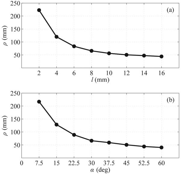
FE simulation results: (a) Impact of bent-tip length l on simulated radius of curvature ρ. (b) Impact of bent-tip angle α on simulated radius of curvature ρ.
C. Testing in Ex Vivo Tissue
In addition to FE simulations, we performed experimental tests in ex vivo porcine liver tissue. We measured the impact of tip length l and tip angle α by creating a number of steerable needles and separately varying those two parameters over a range of values. We inserted each needle into a tissue specimen, and measured the radius of curvature ρ of the resulting needle path.
1) Bent-Tip Needles
Four steerable needles with tip angles α of 45 degrees and tip lengths l of 4 mm, 8 mm, 12 mm, and 16 mm were created to test the impact of tip length. Three steerable needles with tip length l of 12 mm and tip angle α of 30 degrees, 45 degrees, and 60 degrees were created to test the impact of tip angle. All the needles were created from Nitinol tubing with an outer diameter of 0.8 mm and an inner diameter of 0.5 mm, as shown in Fig. 4.
Fig. 4.
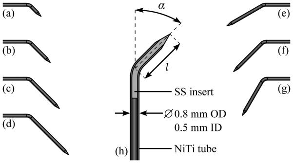
Geometry of bent-tip steerable needles used for testing in ex vivo tissue. In the tip-length test, four needles with tip angle of 45 degrees and tip length of (a) 4 mm, (b) 8 mm, (c) 12 mm, and (d) 16 mm were tested. In the tip-angle test, three needles with tip length of 12 mm and tip angle of (e) 30 degrees, (f) 45 degrees, and (g) 60 degrees were tested. A schematic view (h) shows the construction of the bent-tip steerable needles. A Nitinol (NiTi) tube with outer diameter (OD) of 0.8 mm and inner diameter (ID) of 0.5 mm forms the shaft of each needle. A stainless-steel (SS) insert is bonded inside the tube with epoxy to form the tip. The tip is then ground into a cone using an abrasive wheel, and the tip is bent to the appropriate length and angle.
2) Insertion Protocol
Ex vivo porcine liver tissue obtained fresh from a local butcher was used to simulate human liver tissue. Each of the needles described above was inserted into a tissue specimen ten times, using the two-degree-of-freedom robot described in [26]. The needles were inserted with constant velocity along minimum-radius-of-curvature paths; that is, they were inserted without any axial rotation so that the bent tip caused the needle to curve in a single direction. The insertion velocity was approximately 1.6 mm/s. A small incision in the capsule of the liver was used to introduce the needles, since the bent tips were too large for any available introducer sheath. The needles were inserted for a path length of approximately 100 mm, or until the tip of the needle exited the liver.
3) Ultrasound Imaging
After insertion stopped, the needles were scanned using freehand 3D ultrasound imaging. A SonixMDP ultrasound system (Ultrasonix Research Corp.; Richmond, Canada) with a linear transducer was used to image the needle. This system includes a calibrated electromagnetic tracking system, which enables the collection of 3D ultrasound data. The imaging arrangement was exactly as described in [33]. To measure radius of curvature, the needle was segmented from the 3D ultrasound data by manually localizing the needle cross section in the 50 to 150 image frames captured from each insertion. In previous work [26], we found this manual segmentation to be repeatable to within approximately 0.5 mm. The radius of curvature of the needle was measured by reducing the segmentation points to two dimensions using singular value decomposition, identifying the circular arc that best fit the 2D segmentation points in the least-squares sense, and determining the radius of the arc. The steerable needle’s path was generally very close to lying in a plane; across all tests the average distance of the 3D segmentation points from the reduced 2D points was approximately 0.3 mm.
D. Results in Ex Vivo Tissue
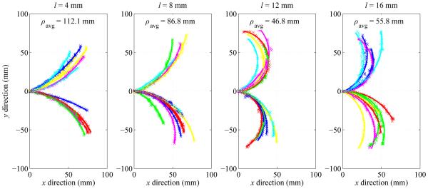
Fig. 5 summarizes the measured radius-of-curvature values as a function of the tip length. Average radius of curvature ρavg (mean ± standard deviation) for l = 4 mm, 8 mm, 12 mm and 16 mm was 112.1 ± 33.0 mm, 86.8 ± 31.8 mm, 46.8 ± 12.2 mm and 55.8 ± 15.4 mm respectively. Tip length l of 12 mm resulted in the smallest average radius of curvature, as well as the least variability in curvature.
Fig. 5.
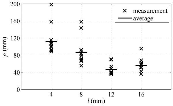
Summary of experimental results showing impact of bent-tip length l on needle radius of curvature ρ in ex vivo tissue. Four tip lengths (4 mm, 8 mm, 12 mm, and 16 mm) were tested. All measured values of ρ are shown, along with average values ρavg for each value of l.
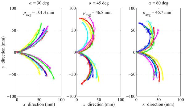
Fig. 6 summarizes the measured radius-of-curvature values as a function of the tip angle. Average radius of curvature ρavg (mean ± standard deviation) for α = 30 degrees, 45 degrees and 60 degrees was 101.4 ± 13.6 mm, 46.8 ± 12.2 mm, and 46.7 mm ± 10.7 mm respectively. Tip angle α of 60 degrees resulted in the smallest average radius of curvature, although there was substantial variability. Tip angle α of 45 degrees resulted in slightly higher average radius of curvature, but with much less variability.
Fig. 6.
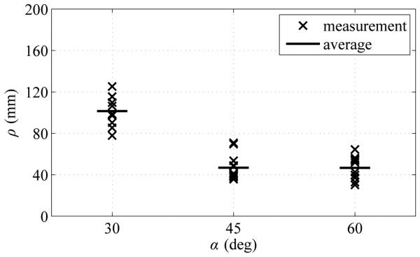
Summary of experimental results showing impact of bent-tip angle α on needle radius of curvature ρ in ex vivo liver tissue. Three tip angles (30 degrees, 45 degrees, and 60 degrees) were tested. All measured values of ρ are shown, along with average values ρavg for each value of α.
Fig. 7 shows the segmentation results and best-fit circular arcs from the tip-length test. Fig. 8 shows the segmentation results and best-fit circular arcs from the tip-angle test.
Fig. 7.
Experimental results showing impact of bent-tip length l on needle radius of curvature ρ in ex vivo tissue. Four tip lengths (4 mm, 8 mm, 12 mm, and 16 mm) were tested. All segmentation results and average values ρavg for each value of l are shown. The needle paths have been moved to a common origin for comparison.
Fig. 8.
Experimental results showing impact of bent-tip angle α on needle radius of curvature ρ in ex vivo liver tissue. Three tip angles (30 degrees, 45 degrees, and 60 degrees) were tested. All segmentation results and average values ρavg for each value of α are shown. The needle paths have been moved to a common origin for comparison.
E. Discussion
In the ex vivo tip-length test, the needle with l = 4 mm and α = 45 degrees showed similar radius-of-curvature values to those previously reported using equivalent bent-tip steerable needles in liver tissue [16], [21]. This is expected, since the needles used in those tests had similar tip and shaft geometries to our needles. The needles with l = 4 mm and l = 8 mm showed more variability in curvature (the needle would occasionally follow a much less tightly curved path) than the needles with l = 12 mm and l = 16 mm. It may be that the heterogeneous liver tissue affects needles with smaller tip lengths more strongly, as they generate less lateral force to compensate for small vessels, fascia, etc. in the liver tissue. A previous study also showed a large amount of variability in radius of curvature using steerable needles with 4-mm tips [25].
During insertion, the needle with α = 60 degrees showed some undesirable behavior, as the needle tip tended to catch on membranes or small vessels. The jerky motion of the needle tip as it hung on obstacles before piercing through was not seen frequently with other tip geometry, and would be undesirable in a clinical setting.
The ex vivo test results and the FE simulation results generally agreed well. For tip length, the ex vivo radius-of-curvature results were within approximately 10 mm of the FE results, except for l = 8 mm, where the FE simulation predicted ρ approximately 20 mm smaller than the ex vivo result. Unlike the FE simulation results—where ρ was approximately equal for l = 12 mm and l = 16 mm—in the ex vivo test results, ρ increased by approximately 9.0 mm on average going from l = 12 mm to l = 16 mm. This may be the impact of factors that were not considered in our FE simulation, such as tissue rupture mechanics or needle-tissue friction. For tip angle, the ex vivo radius-of-curvature results were within approximately 5 mm of the FE results, except for α = 30 degrees, where the FE simulation predicted ρ approximately 35 mm smaller than the ex vivo result. Overall both the ex vivo test results and the FE simulation results showed that bent-tip steerable needles with l > 4 mm and α > 30 degrees can achieve substantially smaller radius of curvature. The ex vivo test results in particular showed that with l = 12 mm and α = 45 degrees, a 0.8-mm tubular Nitinol needle can achieve ρ as small as 50 mm in liver tissue.
III. Articulated-Tip Needle
Two important practical issues preclude the clinical application of steerable needles having rigid bent tips with l = 12 mm and α = 45 degrees in percutaneous RFA of liver tumors. The first issue relates to the introducer sheath, which is a separate rigid needle required to puncture layers of skin and fat to access the liver itself. A bent-tip needle with l > 4 mm and α > 30 degrees cannot fit through a realistic introducer sheath, since a typical 15-gauge introducer has an inner diameter of approximately 1.5 mm. The second issue relates to rotation of the needle during insertion, which is necessary for control of the steerable needle. Rotation of a bent-tip needle results in deformation of the tissue immediately surrounding the tip. As l and α increase, there is more tissue deformation, resulting in decreased targeting accuracy and potentially greater tissue damage. There is also more resistance to rotation with longer tips, potentially increasing torsional deflection, which has previously been shown to be problematic for needle control [34].
Motivated by these issues, we created a new articulated-tip steerable needle. Our implementation of the articulated tip is essentially a bent-tip steerable needle with a miniaturized actuated one-degree-of-freedom rotary joint. The articulated-tip steerable needle switches between a straight needle, which can pass through an introducer and rotate, and a bent-tip needle, which can achieve clinically relevant radius of curvature in liver tissue.
As mentioned in Section I, multiple designs for steerable needles with articulating sections have been proposed. Several groups have described using SMA actuators to articulate steerable needle sections [10]–[12]. While these designs are promising, further refinement is still needed to improve miniaturization, actuation force, and response time. Our design is more similar to the needles described by Swaney et al. [16], who use a passive one-degree-of-freedom flexure tip, and van de Berg et al. [20], who use a short conical tip with an active two-degree-of-freedom ball-and-socket joint. Our needle design is unique in its use of exaggerated tip geometry to achieve tightly curved paths in biological tissue.
The mechanical design and experimental validation of our articulated-tip needle are described in the remainder of this section.
A. Design
1) Articulated Tip
The articulated-tip mechanism is shown in Fig. 9. The mechanism consists of a two-piece 3D-printed hinge, secured by a 0.25-mm stainless-steel pin. The hinge material is MicroFine Green, a proprietary ABS-like material that allows a stereolithography process with a feature resolution of 0.05 mm (Protolabs Inc; Maple Plain, MN). The proximal hinge section mates to a 0.8-mm tubular Nitinol shaft, and is secured with epoxy adhesive. Similarly, the distal hinge section mates to a ground conical stainless-steel tip, and is again secured with epoxy adhesive. Conical tips were selected, rather than the bevel tips commonly seen in prior bent-tip needle steering work [24], [25], because it was easier to make them extremely sharp using our grinding wheel setup.
Fig. 9.
The articulated-tip needle mechanism: (a) Schematic of the articulated tip in the straight configuration. The tip consists of a two-part 3D-printed hinge mechanism approximately 2.0 mm in diameter, secured to a 0.8-mm Nitinol tube, and a 1.0-mm ground stainless-steel tip. (b) Section view of the articulated tip in the straight configuration. A single continuous, pretensioned Nitinol pull wire is used to articulate the needle tip. The pull wire runs through the tubular Nitinol (NiTi) needle shaft, through channels in the proximal hinge section, and is secured to the distal hinge section with adhesive. A ground conical stainless-steel (SS) tip is secured to the distal hinge section with adhesive. (c) Schematic of the articulated-tip in the bent configuration. Nominal tip parameters of l = 9 mm and α = 45 degrees were selected. (d) Micrograph of the assembled tip in the straight configuration. (e) Micrograph of the assembled tip in the bent configuration.
A 0.13-mm Nitinol pull wire runs through the length of the needle shaft, through channels in the proximal hinge section, and is secured to the distal hinge section using epoxy adhesive. This pull wire is wound around a cable pulley in the needle hub, as described below, and allows actuation of the articulated tip. For reasons we describe in Section III-C, the articulated-tip needle is switched between fully straight and fully bent. Contact between the mating hinge components limits the range of motion in both directions. In the current design, tip length l is 9 mm, while tip angle α is approximately 45 degrees. (Because of the manufacturing tolerances of the hinge components the actual maximum value of α was about 3 degrees less than the nominal value.) This tip geometry was selected based on the results of Section II, and the strength limits of the plastic hinges. Although bent-tip needles with l = 12 mm had the smallest average radius of curvature in Section II, the plastic hinge material was not able to support such long tips without occasionally failing.
2) Needle Hub
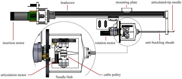
Fig. 10 includes a detail view of the articulated-tip steerable needle hub. The needle hub is a 3D-printed shell that mates to the rotary platform of the needle steering robot. Within the hub is a bearing-mounted cable pulley attached to a spur gear. The spur gear meshes with a pinion gear driven by a DC motor mounted on the rotary platform. The steerable needle shaft and anti-buckling sheath are also both affixed to the needle hub, and the entire needle/sheath assembly is removable from the needle steering robot.
Fig. 10.
Schematic top view of the articulated-tip needle steering robot. DC motors drive a leadscrew for insertion of the needle, a rotary stage for rotation of the needle, and a cable pulley for articulation of the tip. A telescoping sheath prevents the flexible steerable needle from buckling outside of tissue. A detail view shows the removable needle hub attached to the rotatory stage. The needle steering robot is attached to a passive positioning arm using a mounting plate. A standard introducer sheath and connecting luer-lock fixture are omitted.
3) Needle Steering Robot
Fig. 10 shows a schematic overview of the new robot designed to drive articulated-tip steerable needles. The robot is similar to the one described in [24], but with an additional degree of freedom for the active articulation of the needle tip. The robot incorporates three DC motors: one drives a leadscrew for insertion of the needle, one drives a rotary platform that allows rotation of the needle hub, and one drives the cable pulley that allows articulation of the needle tip. A clamping plate allows the entire needle steering robot to be mounted on a passive positioning arm, which is attached to the standard rails on an operating room table.
B. Experimental Validation
1) Method
Ex vivo porcine liver tissue obtained fresh from a local butcher was used to simulate human liver tissue in all testing of the articulated-tip needle. Fig. 11 shows the experimental setup used in validation testing. We evaluated our articulated-tip steerable needle design in three ways.
Fig. 11.
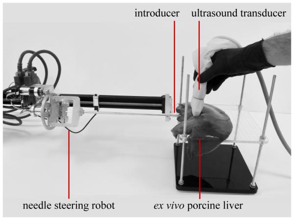
Experimental setup for validation testing of the articulated-tip steerable needle. The needle steering robot is mounted on a passive positioning arm. Ex vivo porcine liver was used to simulate human liver tissue. The articulated-tip needle entered the liver tissue through a 13-gauge introducer sheath. A tracked 2D ultrasound transducer was used to image the needle for validation.
First, to evaluate the articulation mechanism, the tip angle in the bent configuration was compared in free space and in liver tissue. To evaluate the tip angle in free space, the tip was imaged using a microscope with a digital camera attachment. The distal tip section and needle shaft were manually segmented from the micrograph, and the tip angle was measured. To evaluate the angle in tissue, the tip was articulated under 2D ultrasound imaging. The distal tip section and needle shaft were manually segmented from the ultrasound images, and the tip angle was measured.
Second, to evaluate the radius of curvature achieved by the articulated-tip needle, we performed a number of minimumradius-of-curvature insertions (i.e., insertions with the tip kept in the bent configuration) in liver tissue. Each insertion was performed in a new section of liver to keep the needle from following an established track. After insertion stopped, the needles were scanned and segmented using the same method described in Section II for the bent-tip needles.
Finally, we compared the articulated-tip needle design with bent-tip needles in a practical task, by performing a direction change maneuver with both needles. In this maneuver, the needle was inserted along a straight path for approximately 40 mm, before being steered with minimum radius of curvature in one direction for an additional 40 mm. The bent-tip needle was steered along the straight path using open-loop duty-cycle control, while the articulated-tip needle was inserted in the straight configuration. The needle was scanned and segmented after both the initial and final insertion steps, and the maximum deviation δ from the initial vector was measured. The bent-tip needle was the largest needle from Section II that would fit through a 13-gauge introducer, with dimensions l = 4 mm and α = 45 degrees (needle (a) in Fig. 4).
2) Results
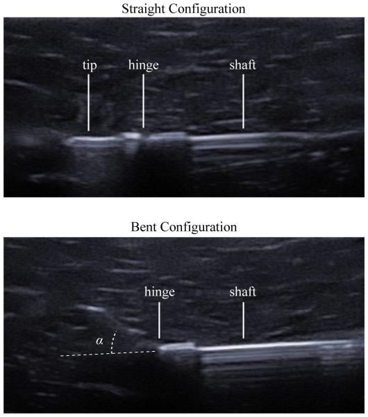
Fig. 12 shows ultrasound images of the articulated-tip needle in the straight and bent configurations. The needle steering robot was able to consistently articulate the needle tip to the same extent in tissue as in free space. In the micrographs shown in Fig. 9, the measured tip angle α was 41.1 degrees, while in the ultrasound images shown in Fig. 12, the measured tip angle α was 41.5 degrees.
Fig. 12.
Ultrasound images of the articulated tip demonstrate the ability of the needle to achieve the straight (top) and bent (bottom) configurations in ex vivo liver tissue. In the bent configuration, tip angle α was found to be 41.5 degrees using manual segmentation.
Fig. 13 shows maximum curvature results for an articulated-tip needle with tip length l = 9 mm and tip angle α = 45 degrees. Over the four tests shown in Fig. 13, the mean curvature was 82.7 mm with a standard deviation of 4.9 mm.
Fig. 13.
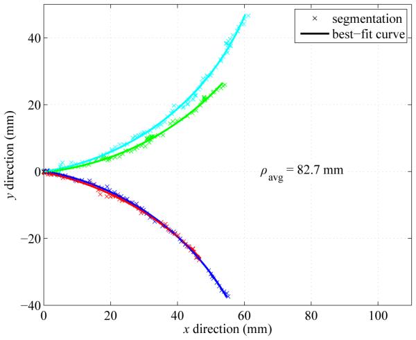
Minimum-radius-of-curvature results with the articulated-tip steerable needle. The needle was inserted with the articulated-tip in the bent configuration. Across four trials in fresh sections of ex vivo liver tissue, the average radius of curvature ρavg was 82.7 mm. The needle paths have been moved to a common origin for comparison.
Fig. 14 shows segmentation results from representative examples of the direction change maneuver. Using a bent-tip steerable needle, the maximum deviation δ from the initial vector was 9.8 mm for the test shown. Using the articulated-tip steerable needle, the maximum deviation δ was 27.7 mm for the test shown. It can be seen in Fig. 14 that the proximal 40 mm of each steerable needle shaft was displaced after the direction change maneuver. The Nitinol needle shafts, which were stiffer than the surrounding liver tissue, relaxed into single smooth circular curves rather than forming segmented straight-to-curved paths. The relaxation of the needle shaft was especially visible for the articulated-tip needle, which exhibited greater displacement δ from the initial vector.
Fig. 14.
Representative examples of direction change maneuver using a bent-tip needle with l = 4 mm and α = 45 degrees, and an articulated-tip needle with l = 9 mm and α ≈ 45 degrees. Each needle was inserted along a straight path for approximately 40 mm, then was steered along the minimum-radius-of-curvature path for an additional 40 mm. In the maneuvers shown in the figure, deviation δ was 9.8 mm using the bent-tip needle, and 27.7 mm using the articulated-tip needle.
C. Discussion
Overall, the validation results described above demonstrate that an articulated-tip needle is able to achieve better curvature in liver tissue than the largest practical bent-tip needle (l ≈ 4 mm). However, there are several issues with the current design, mostly related to construction of the miniature hinges, which we plan to address before applying the design in a liveanimal model. In the current design, the hinge elements are an ABS-like plastic. We are currently exploring machining methods that will allow us to create stainless-steel hinge elements, in order to improve performance, robustness and biocompatibility. Because of their plastic construction, the current hinges occasionally fail if tip lengths longer than about 9 mm are used. Based on the results of Section II, increasing the tip length to approximately 12 mm should reduce radius of curvature to meet the 50-mm design requirement for our procedure. The current design is also sized to pass through a 13-gauge introducer sheath. The overall diameter will need to be slightly reduced to pass through a 15-gauge introducer sheath, which is the largest size that is clinically acceptable for percutaneous RFA of liver tumors.
Unlike in the design of van de Berg et al. [20], in our current design we elected to actuate the tip in a binary sense at the limits of the range of travel (i.e., the needle tip is either fully straight or fully bent). This simplifies the control of actuation, since we no longer need to compensate for the compliance of the pull wires.
Based on observing the needle under ultrasound imaging during articulation, the moving tip easily displaces the liver tissue, making it unlikely that tissue damage is occurring due to tissue stress in the lateral direction. Confirming this would require a detailed histological analysis, which is beyond the scope of this paper. During closed-loop image-guided needle steering, the articulated-tip needle is only rotated in the straight configuration. When the needle is curving in one direction and the steering control software (not described in this paper) determines the needle should curve in a different direction, insertion stops, the needle is switched to the straight configuration, the needle is rotated to the new desired orientation, the needle is switched to the bent configuration, and insertion continues. A more detailed analysis of schemes for closed-loop image-guided control of the articulated-tip needle will be the subject of future work.
Both the flexure-tip design described by Swaney et al. [16] and the ball-and-socket design described by van de Berg et al. [20] could potentially be used with the exaggerated tip geometries we have described. It is unclear how well the passive flexure-tip needle, which relies on an asymmetric bevel to achieve articulation, would work for larger tip lengths and tip angles. The passive flexure also requires duty-cycle control to achieve straight paths, which introduces practical issues such as sensor windup and torsional needle deflection. Active articulated tips can also be used to introduce recognizable motion signatures into medical image data, as in [26], in order to reduce the complexity of image segmentation.
An interesting issue for future consideration is whether existing kinematic models of needle steering, such as the unicycle and bicycle models [14], [35], accurately capture the behavior of these tightly curving steerable needles in tissue. With tighter curvature there is more relaxation of the surrounding tissues and more deviation from the ideal piece-wise circular paths, as seen in Fig. 14.
IV. Conclusion
In this paper, we examined the ability of bent-tip steerable needles to follow tightly curved paths in liver tissue. A simplified FE model of bent-tip needle steering suggested that selection of bent-tip geometry could significantly improve needle curvature. This was confirmed by experiments in ex vivo porcine liver tissue. Specifically, with tip length l = 12 mm and tip angle α = 45 degrees, we found average radius of curvature to be below 50 mm in liver tissue, which is a significant improvement for a 0.8-mm tubular Nitinol needle compared to values reported in the literature. We also described the design of an articulated-tip steerable needle, which uses a miniaturized cable-driven rotary joint to articulate the needle tip between straight and bent configurations. This design allows the needle to have a more asymmetric tip, which results in better curvature, while the straight configuration also allows the needle to pass through an introducer sheath and rotate without extensive tissue deformation. Experimental validation testing demonstrates that the articulated-tip needle is able to achieve tighter curvature in liver tissue than comparable existing bent-tip needles. In future work, we will combine the articulated-tip needle design with our previously described methods for image-guided control [26]. We will also integrate a functional ablation element into the articulated-tip design. The combination of highly steerable needles, closed-loop image-guided control, and a functional ablation element will allow us to test image-guided needle steering for RFA of liver tumors in a live porcine model.
Acknowledgments
This work was supported in part by the National Institutes of Health through R01 EB018849.
Contributor Information
Troy K. Adebar, Mechanical Engineering Department, Stanford University, Stanford, CA, 94035 USA (troy.adebar@gmail.com)
Joseph D. Greer, Mechanical Engineering Department, Stanford University, Stanford, CA, 94035 USA (jdgreer@stanford.edu)
Paul F. Laeseke, Radiology Department, University of Wisconsin, Madison, WI, 53715 USA (plaeseke@uwhealth.org)
Gloria L. Hwang, Radiology Department, Stanford University, Stanford, CA, 94035 USA (glhwang@stanford.edu)
Allison M. Okamura, Mechanical Engineering Department, Stanford University, Stanford, CA, 94035 USA (aokamura@stanford.edu).
References
- [1].van de Berg N, van Gerwen D, Dankelman J, van den Dobbelsteen J. Design choices in needle steering: a review. IEEE Trans. Mechatronics. 2014 eprint ahead of publication, DOI 10.1109/TMECH.2014.2365999. [Google Scholar]
- [2].DiMaio SP, Salcudean SE. Needle steering and motion planning in soft tissues. IEEE Trans. Biomed. Eng. 2005;52(6):965–974. doi: 10.1109/TBME.2005.846734. [DOI] [PubMed] [Google Scholar]
- [3].Glozman D, Shoham M. Image-guided robotic flexible needle steering. IEEE Trans. Robot. 2007;23(3):459–467. [Google Scholar]
- [4].Mallapragada VG, Sarkar N, Podder TK. Robot-assisted realtime tumor manipulation for breast biopsy. IEEE Trans. Robot. 2009;25(2):316–324. [Google Scholar]
- [5].Torabi M, Hauser K, Alterovitz R, Duindam V, Goldberg K. Guiding medical needles using single-point tissue manipulation. IEEE Int. Conf. Robotics Automation. 2009:2705–2710. [Google Scholar]
- [6].Okazawa SH, Ebrahimi R, Chuang J, Salcudean SE, Rohling RN. Hand-held steerable needle device. IEEE Trans. Mechatronics. 2005;10(3):285–296. [Google Scholar]
- [7].Sears P, Dupont P. A steerable needle technology using curved concentric tubes. IEEE RSJ Int. Conf. Intelligent Robots Systems. 2006:2850–2856. [Google Scholar]
- [8].Webster RJ, III, Romano JM, Cowan NJ. Mechanics of precurved-tube continuum robots. IEEE Trans. Robot. 2009;25(1):67–78. [Google Scholar]
- [9].Kratchman LB, Rahman MM, Saunders JR, Swaney PJ, Webster RJ., III Toward robotic needle steering in lung biopsy: a tendonactuated approach. SPIE Med. Imaging: Visualization, Image-Guided Procedures, Modeling. 2011;7964:76941I. [Google Scholar]
- [10].Ayvali E, Liang C-P, Ho M, Chen Y, Desai JP. Towards a discretely actuated steerable cannula for diagnostic and therapeutic procedures. Int. J. Robot. Res. 2012;31(5):588–603. doi: 10.1177/0278364912442429. [DOI] [PMC free article] [PubMed] [Google Scholar]
- [11].Datla NV, Konh B, Honarvar M, Podder TK, Dicker AP, Yu Y, Hutapea P. A model to predict deflection of bevel-tipped active needle advancing in soft tissue. Med. Eng. Phys. 2014;36:285–293. doi: 10.1016/j.medengphy.2013.11.006. [DOI] [PubMed] [Google Scholar]
- [12].Ryu SC, Quek ZF, Koh JS, Renaud P, Black R, Moslehi B, Daniel BL, Cho KJ, Cutkosky M. Design of an optically controlled MR-compatible active needle. IEEE Trans. Robot. 2015;31(1):1–11. doi: 10.1109/TRO.2014.2367351. [DOI] [PMC free article] [PubMed] [Google Scholar]
- [13].Ko SY, Rodriguez y Baena F. Toward a miniaturized needle steering system with path planning for obstacle avoidance. IEEE Trans. Biomed. Eng. 2013;60(4):910–917. doi: 10.1109/TBME.2012.2227741. [DOI] [PubMed] [Google Scholar]
- [14].Webster RJ, III, Kim JS, Cowan NJ, Okamura AM, Chirikjian GS. Nonholonomic modeling of needle steering. Int. J. Robot. Res. 2006;25(5):509–526. [Google Scholar]
- [15].Minhas D, Engh J, Fenske M, Riviere C. Modeling of needle steering via duty-cycled spinning. Int. Conf. IEEE Eng. Med. Biology Soc. 2007:2756–2759. doi: 10.1109/IEMBS.2007.4352899. [DOI] [PubMed] [Google Scholar]
- [16].Swaney PJ, Burgner J, Gilbert HB, Webster RJ., III A flexure-based steerable needle: high curvature with reduced tissue damage. IEEE Trans. Biomed. Eng. 2013;60(4):906–909. doi: 10.1109/TBME.2012.2230001. [DOI] [PMC free article] [PubMed] [Google Scholar]
- [17].O’Leary MD, Simone C, Washio T, Yoshinaka K, Okamura AM. Robotic needle insertion: effects of friction and needle geometry. IEEE Int. Conf. Robotics Automation. 2003:1774–1780. [Google Scholar]
- [18].Alterovitz R, Goldberg K, Okamura A. Planning for steerable bevel-tip needle insertion through 2D soft tissue with obstacles. IEEE Int. Conf. Robotics Automation. 2005:1640–1645. [Google Scholar]
- [19].Wedlick T, Okamura AM. Characterizing pre-curved needles for steering in biological tissue. Int. Conf. IEEE Eng. Med. Biology Soc. 2009:1200–1203. doi: 10.1109/IEMBS.2009.5333407. [DOI] [PMC free article] [PubMed] [Google Scholar]
- [20].van de Berg NJ, Dankelman J, van den Dobbelsteen JJ. Design of an actively controlled steerable needle with tendon actuation and FBG-based shape sensing. Med. Eng. Phys. 2015;37:617–622. doi: 10.1016/j.medengphy.2015.03.016. [DOI] [PubMed] [Google Scholar]
- [21].Patil S, Burgner J, Webster RJ, III, Alterovitz R. Needle steering in 3-D via rapid replanning. IEEE Trans. Robot. 2014;30(4):853–864. doi: 10.1109/TRO.2014.2307633. [DOI] [PMC free article] [PubMed] [Google Scholar]
- [22].Rucker DC, Das J, Gilbert HB, Swaney PJ, Miga MI, Sarkar N, Webster RJ., III Sliding mode control of steerable seedles. IEEE Trans. Robot. 2013;29(5):1289–1299. doi: 10.1109/TRO.2013.2271098. [DOI] [PMC free article] [PubMed] [Google Scholar]
- [23].Burdette EC, Rucker DC, Prakash P, Diederich CJ, Croom JM, Clarke C, Stolka P, Juang T, Boctor EM, Webster RJ., III The ACUSITT ultrasonic ablator: the first steerable needle with an integrated interventional tool. SPIE Med. Imaging. 2010:76 290V–76 290V. [Google Scholar]
- [24].Majewicz A, Marra SP, van Vledder MG, Lin M, Choti MA, Song DY, Okamura AM. Behavior of tip-steerable needles in ex vivo and in vivo tissue. IEEE Trans. Biomed. Eng. 2012;59(10):2705–2715. doi: 10.1109/TBME.2012.2204749. [DOI] [PMC free article] [PubMed] [Google Scholar]
- [25].Majewicz A, Wedlick T, Reed K, Okamura AM. Evaluation of robotic needle steering in ex vivo tissue. IEEE Int. Conf. Robotics Automation. 2010:2068–2073. doi: 10.1109/ROBOT.2010.5509873. [DOI] [PMC free article] [PubMed] [Google Scholar]
- [26].Adebar TK, Fletcher AE, Okamura AM. 3D ultrasoundguided robotic needle steering in biological tissue. IEEE Trans. Biomed. Eng. 2014;61(12):2899–2910. doi: 10.1109/TBME.2014.2334309. [DOI] [PMC free article] [PubMed] [Google Scholar]
- [27].Adebar TK, Greer JD, Laeseke PF, Hwang GL, Okamura AM. Towards robotic needle steering for percutaneous radiofrequency ablation in the liver: procedure-specific workspace analysis. Hamlyn Symp. Medical Robotics. 2015:67–68. [Google Scholar]
- [28].Misra S, Reed KB, Schafer BW, Ramesh KT, Okamura AM. Mechanics of flexible needles robotically steered through soft tissue. Int. J. Robot. Res. 2010;29(13):1640–1660. doi: 10.1177/0278364910369714. [DOI] [PMC free article] [PubMed] [Google Scholar]
- [29].Misra S, Reed KB, Douglas AS, Ramesh KT, Okamura AM. Needle-tissue interaction forces for bevel-tip steerable needles. IEEE RAS EMBS Int. Conf. Biomedical Robotics Biomechatronics. 2008:224–231. doi: 10.1109/BIOROB.2008.4762872. [DOI] [PMC free article] [PubMed] [Google Scholar]
- [30].Mahvash M, Hayward V. Haptic rendering of cutting: a fracture mechanics approach. Haptics-e. 2001;2(3):1–12. [Google Scholar]
- [31].Barbé L, Bayle B, de Mathelin M, Gangli A. Needle insertions modeling: identifiability and limitations. Biomedical Signal Processing and Control. 2007;2(3):191–198. [Google Scholar]
- [32].Kim J, Srinivasan MA. Characterization of viscoelastic soft tissue properties from in vivo experiments and inverse FE parameter estimation. Med. Im. Computing Comput.-Assisted Interventions. 2005;8674:599–606. doi: 10.1007/11566489_74. [DOI] [PubMed] [Google Scholar]
- [33].Greer JD, Adebar TK, Okamura AM. Real-time 3D curved needle segmentation using combined B-mode and power Doppler ultrasound. Med. Im. Computing Comput.-Assisted Interventions. 2014;8674:381–388. doi: 10.1007/978-3-319-10470-6_48. [DOI] [PubMed] [Google Scholar]
- [34].Reed KB, Okamura AM, Cowan NJ. Modeling and control of needles with torsional friction. IEEE Trans. Biomed. Eng. 2009:2905–2916. doi: 10.1109/TBME.2009.2029240. [DOI] [PMC free article] [PubMed] [Google Scholar]
- [35].Park W, Kim JS, Zhou Y, Cowan NJ, Okamura AM, Chirikjian GS. Diffusion-based motion planning for a nonholonomic exible needle model. IEEE Int. Conf. Robotics Automation. 2005:4600–4605. [Google Scholar]


