Significance
Transient permeabilization of the cell membrane is needed to introduce genes and drugs into cells, and electroporation (the physical breakdown of a bilayer membrane under an external electric field) is the most common method to achieve this. By applying an electric field to an artificial lipid bilayer, we have been able to visualize the presence of individual electropores in the bilayer. We exploit droplet interface bilayers (formed from the contact between an aqueous droplet and a hydrogel surface immersed in a phospholipid/oil solution) to provide simultaneous single-channel electrical recording and fluorescence imaging of the bilayer.
Keywords: droplet interface bilayer, electroporation, toroidal pores, optical single-channel recording, lipid bilayers
Abstract
Electroporation is a widely used technique to permeabilize cell membranes. Despite its prevalence, our understanding of the mechanism of voltage-mediated pore formation is incomplete; methods capable of visualizing the time-dependent behavior of individual electropores would help improve our understanding of this process. Here, using optical single-channel recording, we track multiple isolated electropores in real time in planar droplet interface bilayers. We observe individual, mobile defects that fluctuate in size, exhibiting a range of dynamic behaviors. We observe fast (25 s−1) and slow (2 s−1) components in the gating of small electropores, with no apparent dependence on the applied potential. Furthermore, we find that electropores form preferentially in the liquid disordered phase. Our observations are in general supportive of the hydrophilic toroidal pore model of electroporation, but also reveal additional complexity in the interactions, dynamics, and energetics of electropores.
Maintenance of an intact cell membrane is vital for cell viability; it provides the barrier that prevents cell lysis and controls permeability to the external environment. However, intentional transient permeabilization of the membrane is also exploited as a means to introduce genes or drugs into an organism, and targeted permanent disruption of plasma membranes is an effective means to eliminate specific cells (1–3).
Electroporation (or electropermeabilization)—the physical breakdown of a bilayer membrane under an external electric field—is a long-standing, popular method used to control the integrity of a cell membrane. Since its discovery and the first investigations in the 1960s and 1970s (4, 5), electroporation has been used in a wide range of applications, including gene transfection (6), wound and water sterilization (7, 8), tumor ablation (9, 10), electrochemotherapy (11, 12), and transdermal drug delivery (13). Furthermore, links to defibrillation damage have been highlighted (14).
Toroidal Pore Model
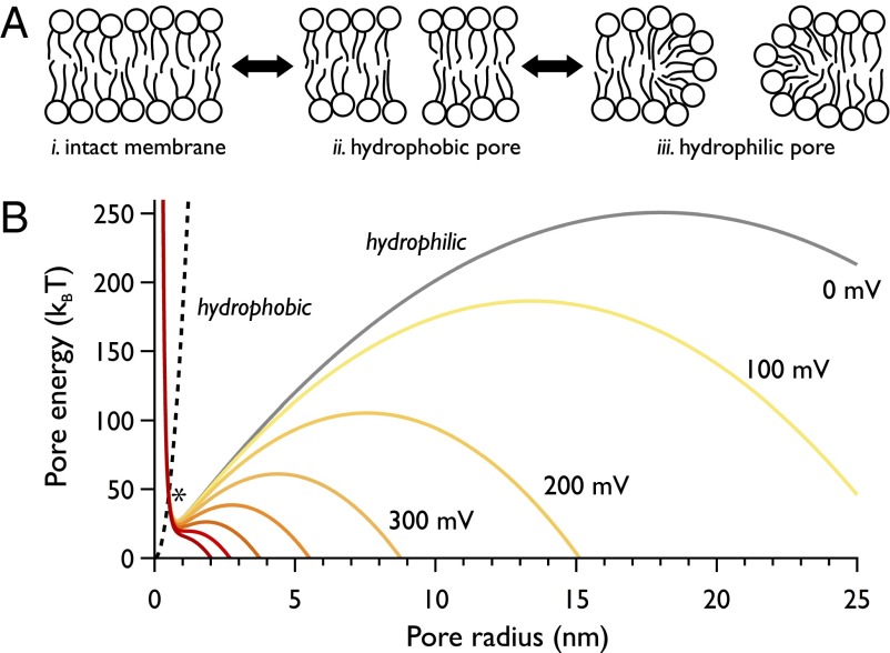
The transient aqueous pore hypothesis provides the basis of our current understanding of electroporation (Fig. 1). In this model, the kinetics of pore formation is governed by the transition over an energy barrier E* created by the intersection of potentials corresponding to two distinct pore configurations: (i) a hydrophobic pore, where the lipids are simply parted with respect to an intact membrane, and (ii) a hydrophilic, toroidal pore (15). In this work, when describing a toroidal pore, we refer to a conductive pore, with the lumen lined and stabilized by lipid head groups (Fig. 1A). At small radii, hydrophilic pores reside within a local energy minimum (16); at large radii, there exists a local maximum (with associated critical radius rc), beyond which a pore may grow indefinitely. The application of a transmembrane potential modifies the free energy of the hydrophilic pore such that its free energy, along with this barrier, is reduced (Fig. 1B). At a critical potential Vc, this barrier to unbounded pore expansion is lost, and the defect grows until the bilayer is destroyed.
Fig. 1.
The transient aqueous pore hypothesis. (A) The sequence of lipid rearrangements that lead to a conductive (hydrophilic, or toroidal) pore. Formation proceeds from the unperturbed membrane (i) via a nonconducting hydrophobic pore generated by the parting of lipids but involving no molecular reorientation (ii). At sufficiently large radii, however, lipids rearrange and head groups line the pore lumen (iii). (B) Electropore energy landscape highlighting the hydrophobic and hydrophilic pore free energies (dashed and solid lines, respectively) using the equations and parameter values from ref. 16, which are those commonly used in theoretical electroporation literature. Their intersection is indicated at the asterisk (*); we refer to this energy barrier as E*. The gray line is the hydrophilic pore energy at Vapplied = 0 mV; yellow through to red plots the reduction in free energy from 100 to 700 mV. Increasing the applied potential difference is predicted to lower and broaden the local energy minimum that supports the hydrophilic pore, and lower the barrier to unbounded pore expansion.
Previous Imaging of Electropores
Theory and simulation have provided a rich source of predictions regarding the properties of electropores. For example, molecular dynamics simulations have predicted the evolution of hydrophilic pores takes place from an initial membrane-spanning water file (17–19). However, there is a conspicuous mismatch between this level of predictive power and the information yielded by experiment.
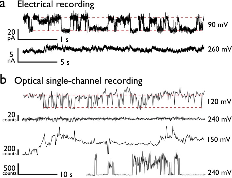
Studies visualizing the presence of electropores are extremely limited. Techniques such as rapid freezing of electroporated erythrocytes (20) have provided snapshots suggestive of pore formation, but these have been disputed (21). The transient nature and small size of electropores place significant limitations on the measurement of electropore dynamics, and more fundamentally on their direct detection. Electrical single-channel recording (SCR) can resolve these dynamics at high time resolution (22, 23); however, SCR is limited in that it can only detect the total current across the membrane, and is thus unable to resolve whether conductance events are due to single or multiple permeabilization events. Indeed, the most common characteristic for electroporation in SCR would be a “noisy” trace that precedes bilayer rupture (see Fig. S5A, Lower).
Fig. S5.
Electropore behavior. (A) Electrical traces. At low potentials, we observe electrical behavior consistent with that of a lone pore, although we can only assume a single defect is present. At higher potentials, the current recording can only report on the total bilayer conductance, and so the component defects are unresolved. (B) oSCR reveals individual pore behavior from an ensemble of pores. We observe a range of opening and closing processes, with discrete bursts, rapid fluctuations, sudden pore closure, and stable behaviors. At high potentials, all of these behaviors are observed and no one process dominates.
A better insight into electropore formation would be provided by methods capable of observing the dynamics of electropore formation in real time. Few dynamic experimental imaging studies of these defects exist. Pioneering work in giant unilamellar vesicles (GUVs) has led to methods for assessing line tension, studying pore closure and formation times, and the dynamics of solute flow between the internal and external volumes (24, 25). For example, GUVs have been used to show transport across a membrane can be achieved by an electroporation pulse only 10 ns in duration (26). However, many of these systems typically examine small numbers of large, microscopic pores, much larger than the nanoscopic pores observed in cell systems (20–120 nm) (20), predicted by molecular dynamics simulations (17, 19) and implied by cellular uptake assays (27).
Here, we seek to improve our experimental understanding of electroporation by exploiting optical single-channel recording (oSCR) (28, 29) to image individual voltage-induced defects in a lipid membrane by detecting a fluorescent signal proportional to the flux of Ca2+ flowing through a pore. Very recently, we detected electroporation events using fluorescence signals generated by K+ ionic flux (30). Although this work showed electropores formed under the same applied potentials as reported here, it was limited by the slow response and poor sensitivity of K+-responsive fluorophores. In this work, the enhanced sensitivity of fluorogenic Ca2+-sensitive dyes allows us to characterize electroporation kinetics in detail.
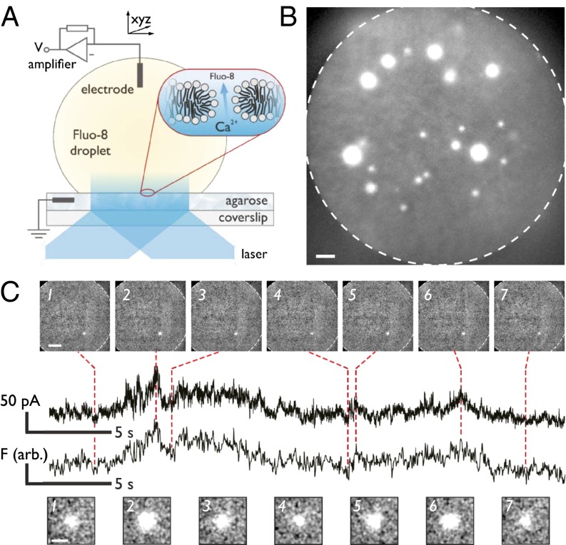
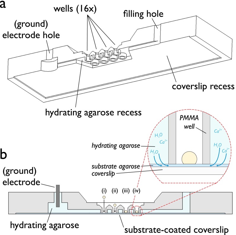
We previously developed droplet interface bilayers (DIBs) (31) (Fig. 2A and Fig. S1) to create highly stable, size-adjustable artificial bilayers that are straightforward to image using total internal reflection fluorescence (TIRF) microscopy, providing imaging that is sensitive to signals originating at the bilayer. DIBs are formed when a planar hydrogel surface and an aqueous droplet are brought into contact in a lipid-in-oil solution. Using DIBs, we visualize the ionic flux through nanoscopic membrane defects in real time over a large area (≥14,000 µm2). We classify electropore behavior and compare it to the current model, helping bridge the gap between theory, simulation, and experiment.
Fig. 2.
Imaging electroporation. (A) Cartoon of the DIB experimental setup. Contact between a planar substrate and an aqueous droplet that both bear a self-assembled lipid monolayer produces the bilayer. Expanded region indicates the location of the bilayer and depicts a toroidal electropore, along with the direction of motion of Ca2+ ions, enabling visualization of individual electropores by TIRF microscopy. (B) Pores are observed as bright spots within the bilayer. The edge of the bilayer is indicated by the dashed line. The image is the maximum pixel intensity of 40 frames recorded at 61.7 Hz at an applied potential of 485 mV. (Scale bar: 10 µm.) (C) When a single pore is observed (160 mV), the electrical (Upper) and fluorescence signals (Lower) correspond. Upper images: frames at 32.9 Hz demonstrating only a single pore is present. (Scale bar: 25 µm.) Lower images: expanded views of the pores showing the fluctuation in spot radius. (Scale bar: 5 µm.)
Fig. S1.
Detail of experimental setup, highlighting the main features of the PMMA device used in these experiments. (A) Cut-through view of the device. (B) Side view of A. Once the substrate agarose (dark blue) has been spun onto a coverslip, this is then placed within the recess seen in A. Hydrating agarose (light blue) is then flowed through the device, where it flows around the wells. An Ag/AgCl electrode is inserted into the hydrating agarose via one of the filling holes. Roman numerals represent placing a droplet (yellow) within a well (i and ii), its sinking toward the substrate under gravity (ii and iii), and formation of a bilayer (iv). (Inset) Cartoon of a well containing a DIB. The hydrating agarose does not cover the substrate within the wells. Dotted arrows indicate movement of water and electrolyte into the substrate from the hydrating agarose.
Results
Fluorescence Imaging of Electroporation.
DPhPC (1,2 diphytanoyl-sn-glycero-3-phosphocholine) bilayers were formed and subjected to DC potentials (see SI Experimental Methods for full experimental details). Upon application of a potential difference of ≥90 mV, individual electropores form and calcium is driven from the substrate into the droplet where it is bound by the fluorogenic Ca2+ indicator dye Fluo-8. Individual electropores are visualized as isolated bright spots in the bilayer (Fig. 2B and Movie S1). oSCR enables the location and conductance from many individual pores to be monitored in parallel. For a DIB containing a single pore, there is direct correlation between electrical and fluorescence signals (Fig. 2C); for multiple pores, the sum fluorescence trace corresponds to the total ionic current across the bilayer (Fig. S2). This decomposition of multiple signals is inaccessible in a direct electrical recording.
Fig. S2.
Correlating fluorescence and electrical recording. A triplet of pores at 200 mV generates an electrical signal that comprises the three individual pore currents, EA+B+C (red). These can be revealed using fluorescence data (FA, FB, and FC, black). Fluorescence traces are overlaid atop duplicates of the total electrical signal to ease visualization of its components. The image is the maximum intensity over 200 frames recorded at 32.9 Hz. (Scale bar: 25 μm.)
I–V Response.
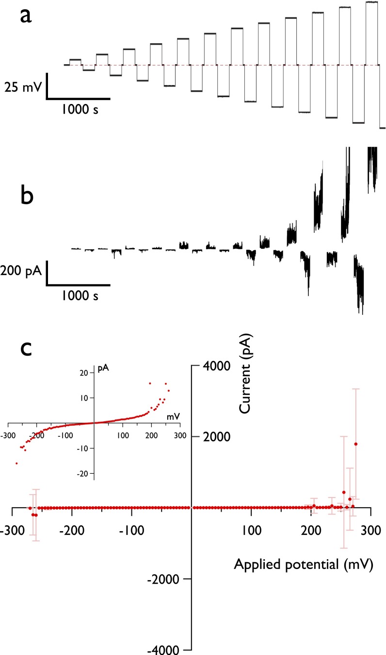
We first examined the ensemble current–voltage (I–V) response (Fig. S3). As expected, at low potentials, the bilayer is essentially nonconducting (7.99 ± 0.27 × 10¹⁰ Ω). Current fluctuations appear above ∼100 mV (onset, 111 ± 41 mV), and the I–V curve becomes increasingly nonlinear until breakdown. Vc was found to be 224 ± 39 mV (n = 17) when the agarose and droplet contained 1.5 M KCl, and 272 ± 29 mV (n = 7) when the agarose contained 750 mM CaCl2. The apparent stabilizing effect of calcium is perhaps a result of the divalent cation having a stronger electrostatic interaction with the lipid head groups than K+, as has been reported in other membrane systems (22).
Fig. S3.
Electrical characterization of DIBs. (A) Voltage protocol applied to DIBs to obtain breakdown voltages and I–V curves such as shown in C. The droplet is subjected to incrementally increasing positive and negative potentials. Between each 180-s application of voltage, there is a 30-s rest period at 0 mV, indicated by the dashed line. (B) Current response of a bilayer under a voltage protocol, shown from the period in which electroporation has started. Electrolytes were identical to those used in oSCR experiments. Bilayer capacitance charging and the rest periods at 0 mV have been removed for clarity. (C) I–V response characteristic of a DPhPC DIB. A voltage protocol exposed the membrane to ±5-mV stepwise increases in potential up to ±300 mV for 180 s, with each increment separated by 30 s at 0 mV. Points are the mean current value at each applied potential. Error bars are the SD. (Inset) Expanded region of the I–V curve.
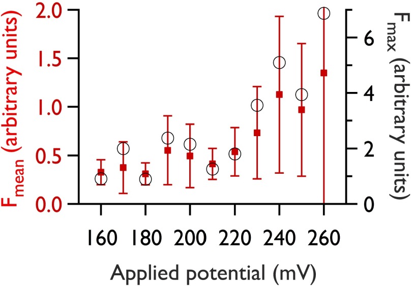
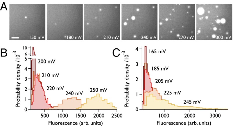
The I–V response is mirrored in the fluorescence data (Fig. S4); however, only by using oSCR are we now able to attribute this to an increase in both the number of pores and their size (Fig. 3), rather than solely by the expansion of a single pore. In examining the distribution of fluorescence intensities from electropores as a function of applied voltage for a single pore (Fig. 3B), we observe a broadening of the distribution of pore intensities, with a mean that increases with the applied potential. This observation is consistent with a broadening of the local energy minimum at higher applied potentials (Fig. 1B) (16). We also note that, for an ensemble of pores (Fig. 3C), a population of small pores remains even at high potentials, as can also be seen in Fig. 3A.
Fig. S4.
Typical fluorescence–voltage behavior during electroporation. Red squares: mean intensity of all pores within the field of view (512 × 512 pixels; visible bilayer area, 0.0188 mm2) during an oSCR recording at increasing potential. Error bars represent ±1σ. Black circles: maximum fluorescence intensity across the same run.
Fig. 3.
Ensemble response. (A) Number and size of pores increases with voltage: maximum intensity images from >1,000-frame recordings on the same bilayer. (Scale bar: 25 µm.) (B) Histograms of oSCR intensities for a single pore within a bilayer experiencing an increasing applied potential. Pore amplitudes were obtained by 2D Gaussian fitting to the oSCR spot throughout the 1,000-frame movie. (C) Data from an ensemble of spots (n = 2,424, 3,137, 5,641, 8,411, and 9,428, respectively) as the potential is varied.
Pore Taxonomy.
Individual electropore signals fluctuate in a variety of modes (Fig. S5): switching between quiescent and noisy states; rapid rises to high currents; heavy current fluctuations; long periods at stable radii; or the sudden collapse of a pore. Electropore gating and extended opening have been previously reported using electrical recording (5, 22, 23); however, here, by isolating individual oSCR signals, we are able to extend observation of these phenomena to higher potentials, where the individual signals would be obscured in a purely electrical measurement. We have observed that all of these modes can occur at elevated potentials, with no apparent favor of one mode over another.
Visualization of pores during the application of potential across the bilayer allows us to confirm when there is a single pore present. This often occurs at low (80–110 mV) potentials, and we may determine the conductance of these defects and thus estimate our sensitivity. Our oSCR observations of isolated electropores indicate that conductances as small as 400 pS may be (optically) detected, a sensitivity over five times better than obtained using potassium-sensitive dyes (30). This current is similar in magnitude to the current measured directly at the onset of electroporation where presumably only a single electropore is present (Fig. S5A, Upper).
Approximating an electropore as a cylindrical defect (SI Experimental Methods), we obtain an approximate pore radius of 0.22 nm for the smallest pores (those detected at the onset of electroporation). This value will be an underestimate as the field experienced in the region of the pore will be reduced upon its formation (32, 33); however, it supports previous suggestions that the smallest electrically conductive pores are those able to accommodate at least a single file of ions. This value is also on the order of the smallest pores found in experimental and theoretical studies (19, 27, 34–36).
Electropore Diffusion.
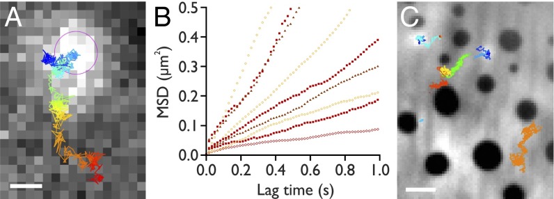
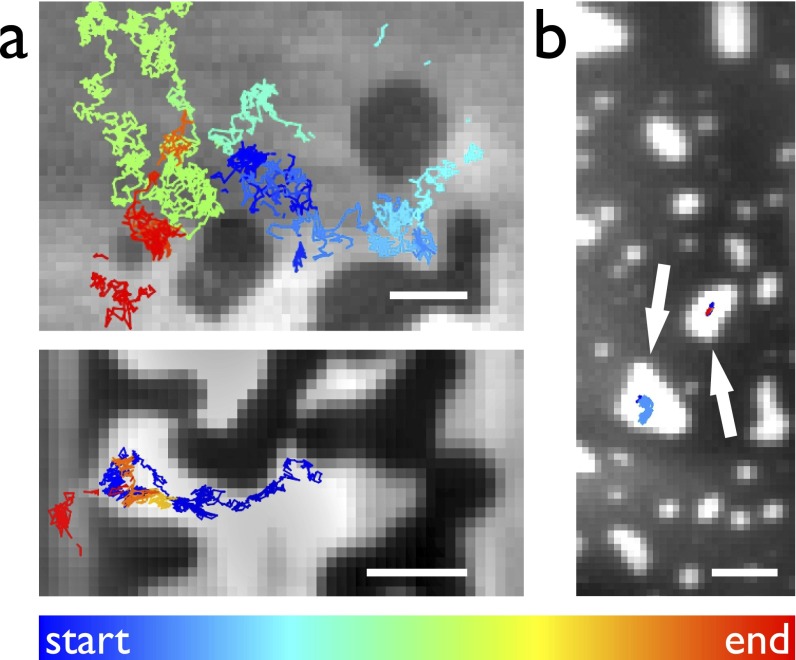
Individual, diffusing electropores can be tracked within the membrane (Fig. 4A). Mobile pores were generally small and exhibited a broad distribution of lateral diffusion coefficients (Dlat) (Fig. 4B) with a mean value of 0.67 ± 0.58 µm2⋅s−1 (max: 2.7 µm2⋅s−1; min: 0.037 µm2⋅s−1). The lateral diffusion coefficient of these pores showed no obvious correlation with applied potential.
Fig. 4.
Electropore diffusion. (A) A single frame from an oSCR stack (61.7 Hz) of a diffusing electropore, recorded at 200 mV, overlaid with the tracking trajectory (blue, 0 s, to red, 16.2 s). The pink circle indicates the detected location of the spot in this frame. (Scale bar: 2 µm.) (B) Representative mean-squared displacement versus time plots. Open circles: 180 mV; filled squares: 200 mV; open lozenges: 260 mV; filled triangles: 330 mV. Mean Dlat = 0.67 µm2⋅s−1 (n = 46). We observe no obvious correlation of diffusivity with the applied potential. (C) Electroporation in a DPhPC/DPPG/cholesterol (1:1:1) phase-separated DIB. Median image of 500 frames recorded at 99.4 Hz. Electropores form in the (bright) Ld phase, diffusing around the (dark) Lo regions. Colored overlays show the trajectories of different tracked electropores. (Scale bar: 5 µm.)
Phase Dependence of Electroporation.
Molecular dynamics simulations predict that electroporation is favored in lipid regions of greater disorder (37). We electroporated phase-separated DIBs using two ternary mixtures, DPhPC/dipalmitoyl phosphoglycerol (DPPG)/cholesterol and DPhPC/brain sphingomyelin (bSM)/cholesterol (both molar ratio, 1:1:1), which exhibited liquid ordered (Lo) and liquid disordered (Ld) phase coexistence. Domains were visualized using 1 mol% of the lipophilic dye DiI, which partitions into the liquid disordered phase. Fig. 4C shows a median-averaged image from such an experiment, overlaid with trajectories of electropores diffusing in the membrane (see also Fig. S6 and Movies S2 and S3). Pores are seen to move within the Ld phase, moving between but not into Lo domains.
Fig. S6.
Electropore diffusion in phase-separated membranes. Median images of between 500 and 7,000 frames recorded at 99.4 Hz (A) or 49.9 Hz (B). Colored trajectories show motion of electropores; their color indicates the time at which the trajectory begins with respect to the start of the recording. (A) DPhPC/DPPG/cholesterol, 1:1:1. Electropores in the Ld phase diffuse around, but not within, areas of Lo lipid. The lower panel shows an electropore passing between a gap in the ordered region. (B) In a DIB formed of DPhPC/bSM/cholesterol, 1:1:1, electropores form and are trapped within the small regions of the Ld phase, marked by arrows. (Scale bars: 5 μm.)
Pore Closure and Bilayer Rupture.
Experiments carried out in cells have indicated that some pores can remain open for hundreds of seconds (27, 38, 39), whereas closure is typically in the nanosecond-to-microsecond range in simulations (19, 33). Within the time resolution of our experiments (16 ms), we observe pores that close immediately upon removal of the applied potential.
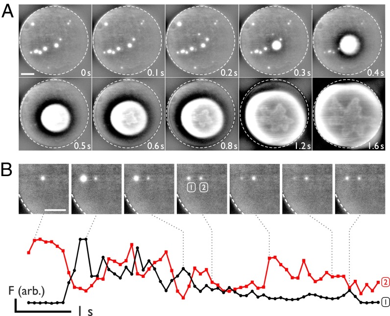
Uncertainty exists as to whether bilayer rupture is a result of a single expanding pore, or a collection of smaller defects (25, 40). Fig. 5A shows consecutive frames during DIB breakdown: we observe bilayer rupture to only take place via a single electropore. During the growth of this critical defect, other pores shrink and seal, likely as the sudden increase in conductance relaxes the potential across the membrane. Once started, the rupture process cannot be arrested. These observations support the transient aqueous pore model, where once a defect above the critical radius rc is formed, there is rapid and uncontrolled expansion of the pore (15, 16). We note that the rupture patterns we observe (Fig. 5A, lower row) are similar to the floral instability patterns seen in rupturing multilamellar vesicles (41).
Fig. 5.
Rupture and cooperativity. (A) Bilayers always rupture from a single pore. Images show snapshots of rupture of a bilayer after irreversible expansion of a single electropore at 200 mV. The dashed circle highlights the bilayer edge. Each image is a 100-ms exposure. (B) Two neighboring pores expand and contract in contrary motion. Red and black lines plot the oSCR intensity for the right and left pores, respectively. Images are 100-ms frames; their location in time with respect to the fluorescence data is indicated by the dotted lines. (Scale bars: 25 µm.)
In phase-separated bilayers, the Lo boundary delimiting the disordered regions in which electropores can form (Fig. S6B) does not appear to restrict the expansion of the pore at elevated potentials; rupture occurs from one disordered region and proceeds to destroy the whole bilayer.
Interactions Between Electropores.
A further question that has been raised is whether electropores are able to coalesce (25, 42). We only observe isolated pores and do not observe electropore coalescence in our experiments. Additionally, we have observed anticorrelation in pore currents (Fig. 5B), either when small pores are in close proximity (several tens of micrometers), or when a critical pore exists within the membrane (Fig. 5A). Such behavior would be consistent with modulation of either the local electric field or membrane surface tension by the presence of other pores.
Gating Kinetics.
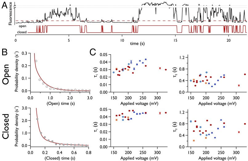
Large pores were observed to persist throughout the duration of our experiments; however, at the onset of electroporation, we observe discrete fluctuations in pore radius. This can be maintained for periods of up to several hundred seconds, and can be observed in both electrical and fluorescence recordings (uppermost traces, Fig. S5 A and B). Given that this behavior arises at the onset of defect formation, we attribute this type of conductance to the opening and closing of the smallest possible pore. This is supported by the value of our estimation for the radii of these defects. To gain a more detailed understanding of the energetic barrier to pore formation, we examined these gating kinetics in detail. Electropores were imaged over a range of potentials, with a transition between open and closed states defined by a threshold set at three times the SD of the background intensity (Fig. 6A). Pore lifetimes were best fit by double exponentials (Fig. 6B), compared with single or stretched exponentials. Results from analysis of ≥1,900 pores are shown in Fig. 6C; the prominent feature is that these characteristic lifetimes are essentially invariant with the applied potential.
Fig. 6.
Kinetics of small electropores. (A) Fluctuating intensity of an isolated electropore (black trace; Upper) with detected open and closed states (red; Lower). The red dashed line is the threshold that defines the open and closed states, equal to 3σ of the background fluctuations. (B) Representative histograms at both extremes of Vapplied showing exponential fits to the open and closed time distributions that exhibit two decay constants. The applied potential was 260 mV for the open lifetime and 160 mV for the closed lifetime histogram. (C) Electropore lifetimes vs. Vapplied. Different markers represent data from experiments carried out on different bilayers on different days, but under identical experimental conditions. Number of pores analyzed, ≥1,900. Temporal resolution, 16.21 ms.
Discussion
oSCR has enabled us to make a wide range of quantitative measurements characterizing electropore behavior. This work is unique in reporting the real-time dynamics of isolated electropores within an ensemble of defects. Electrical measurements of electroporation typically show noisy, poorly resolved features; we are able to attribute this noisy fluctuating signal to an ensemble of individual permeabilization events in the bilayer, rather than a more generalized mechanism of bilayer disruption.
The diffusion of electropores, along with their rapid fluctuation in conductance, confirms that their structure is highly dynamic. Across the range of applied potentials, the majority of tracked pores were of a similar size; in this case, the apparent lack of correlation between the diffusion coefficient and the applied potential may be expected as the electric field around a pore is predicted to be radially isotropic (32). However, the sample size is small (n = 46), and any presumed relationship between Vapplied (hence pore size) and Dlat may be further complicated by the rapidly fluctuating pore radius.
Examining the distribution of oSCR intensities as function of potential (Fig. 3C) shows that a population of smaller pores is retained as the potential is raised. Although the distribution becomes less dominated by them, at elevated voltages the smallest observable defects remain across the full range of the applied potential difference. This behavior is consistent with a toroidal pore model in which the crossing point between the hydrophobic and hydrophilic energy surfaces (Fig. 1B) is not susceptible to a change in the applied potential. The broadening of the oSCR intensity distribution (and hence pore radius) as the applied potential increases supports the common depiction of hydrophilic energy curves: the potential well that supports hydrophilic pores widens and shifts to larger radii at elevated potentials.
Individual electropores can remain open for tens to hundreds of seconds under an applied voltage; however, the proportion of these instances relative to the rapidly gating electropores is low. As a result, the data on fluctuating pores report on the kinetics associated with the transition over the hydrophilic–hydrophobic energy barrier: the open time represents the depth of the energy well corresponding to a hydrophilic pore; the closed time corresponds to the height of the barrier for hydrophilic pore formation. The independence of open times on applied potential (Fig. 6C, Upper) implies that, in our experiments, there is no significant deepening of the hydrophilic pore well with applied potential. A rise in potential does broaden this local minimum, granting access to a greater range of pore radii (Fig. 3 B and C), but we do not observe that pores at these higher potentials are more stable. The suggestion that the applied potential does not influence the kinetics of pore opening is consistent with previous work by Wilhelm et al. (40).
The closed time similarly does not vary with increasing potential, implying that the height of the energy barrier to hydrophilic pore formation is also relatively constant, i.e., the point where hydrophobic and hydrophilic potentials cross, E*, is insensitive to applied potential. (This is further supported by our observation of small electropores at high potentials.) This is consistent with the proposed mechanism for the transition between a hydrophobic and a hydrophilic pore: the lipid rearrangement is predominantly driven by the minimization of the unfavorable interaction between water and the tail groups. Similarly, collapse of a conducting defect will always require the coming together of the water-lined toroidal pore walls, and the physical forces associated with this, along with those governing the transition of lipids back to a parallel, unperturbed bilayer arrangement, are unlikely to be greatly modulated by the potential. The idea that the crossing point between these potentials exists at a fixed location in terms of energy and radius has been hypothesized previously (36).
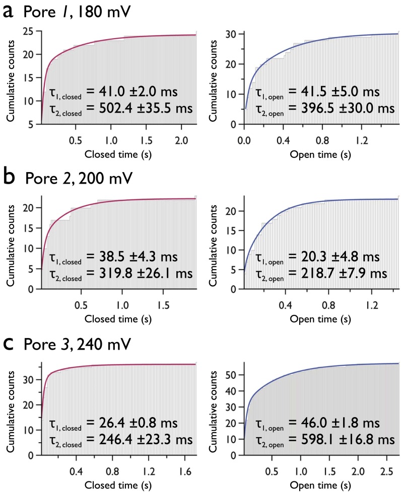
The reason for the open and closed times exhibiting two components is less clear. The histograms used to determine the pore lifetimes in Fig. 6 contain data from more than 1,900 electropores; however, analysis of individual pores shows that single pores also exhibit double-exponential behavior (Fig. S7). Each defect appears able to exist in either a short- or long-lived open or closed state. We tentatively attribute the longer timescales, τ2,open ∼ 400 ms and τ2,closed ∼ 600 ms, to the process of hydrophilic pore opening and closure, respectively. The observation that τ2,closed > τ2,open is consistent with the barrier to conductive pore formation being larger than the barrier to pore collapse. The shorter times (τ1,open, τ1,closed ∼ 30–40 ms) have a less obvious origin, and are not supported by the simple toroidal pore model. Bimodal rates for both opening and closing would be consistent with a number of different kinetic models, for example, a single closed state in equilibrium with two distinct open states. Molecular dynamics simulations have suggested that brief pore openings may be the result of conductive hydrophobic pores (43). However, this would require such a conductive hydrophobic pores to be long-lasting, with no favorable transition to the hydrophilic toroidal state. Alternatively, these lifetimes may be the result of brief (hydrophilic) openings as the potential only just overcomes E*, in which case the pore opens, reduces the local electric field, and rapidly closes. Future work will help move beyond this speculation as to the nature of these kinetics.
Fig. S7.
Lifetimes for single pores. Analysis of isolated pores indicates that the double-exponential fits are appropriate for the ensemble histograms (Fig. 6 in main manuscript), and that the two lifetimes are not a result of two distinct populations of pore. Pores 1 and 2 (A and B) were recorded on the same bilayer and 3 (C) from a different bilayer. All three exhibited different mobilities, demonstrating that the double-lifetime behavior is independent of the experiment and pore diffusion properties.
Our observations point toward established defects influencing the nature of new ones: anticorrelation in pore fluctuations and the relaxation of the electrical stress on the membrane when a very large pore exists (Fig. 5 and Movies S4 and S5) are evidence of this. These factors are very likely the cause of the range of fluctuation regimes we observe (Fig. S5), and may contribute to the maintenance of small pores at higher potentials (Fig. 3C). The way in which biological membranes dissipate or augment these local tensile or electrical stresses during electroporation is therefore of great interest if we are to further understand this phenomenon in vivo.
Limitations.
The events we detect do not provide a direct measurement of pore size: the fluorescent events corresponding to the “cloud” of ion flux flowing through each pore is larger than the pore itself. Although we can resolve the locations of individual pores to within a few tens of nanometers, we cannot image their structure directly. Furthermore, optical detection of electropores is unavoidably constrained by the diffraction limit, and, although unlikely (42), if multiple pores exist within the diffraction-limited point spread function (FWHM = 0.59 µm), they will be essentially unresolved.
The time resolution of our current experiments (16 ms) also limits our ability to investigate electroporation kinetics. Such a restriction means that we are unable to observe electropore dynamics under the (typically) nanosecond-to-microsecond pulsed AC protocols that are typically used to electroporate cells. These rapid, transient applications of potential are designed primarily to reduce thermal damage that would otherwise kill the cell. However, in our experiments, with a small number of isolated pores over the bilayer area, we observe no measureable temperature changes associated with current flow.
Last, the presence of a supporting agarose substrate might potentially perturb electropore kinetics; however, our observations of Brownian diffusion of electropores and bimodal kinetics independent of diffusion (Fig. S7) imply that any effect of the substrate is minor.
Summary.
Our results are in support of the hydrophilic toroidal pore model; however, the kinetics we resolve are not completely explained by this simple scheme. Under an electric field, electropores appear and disappear within the membrane in a stochastic manner, and exhibit constantly fluctuating radii. Pores become more numerous and fluctuate around greater radii as the applied potential is increased, as is consistent with our current understanding. Electroporation in this system appears not to be characterized by a single behavior, but by a range of fluctuation regimes. These observations point toward more complex interactions between electropores, indicating that local variations in the electric field or surface tension owing to pores already present limit the size of newly formed defects.
The ability to decompose the total current across the bilayer due to electroporation into the component contribution of individual electropores has enabled us to shed further light on the physical mechanism that controls this important phenomenon. The next steps must be to bridge the gap between the insights afforded by these in vitro models, and the realities of electroporation in vivo.
Experimental Methods
Materials.
Stocks of 1,2 diphytanoyl-sn-glycero-3-phosphocholine (DPhPC), 1,2-dipalmitoyl-sn-glycero-3-phosphoglycerol (DPPG), bSM, and cholesterol (all Avanti Polar Lipids) were stored in chloroform at −20 °C. The 8.7 mg⋅mL−1 solutions of lipid in hexadecane were produced from these stocks before each experiment. All aqueous solutions were prepared using doubly deionized 18.2 MΩ⋅cm MilliQ water. Low-melt agarose (Sigma-Aldrich) solutions were freshly prepared each day and kept at 90 °C to ensure homogeneity. Potassium chloride solutions were buffered with 10 mM Hepes, adjusted with potassium hydroxide, treated with Chelex resin (200–400 mesh; Bio-Rad) to remove divalent cations, and filtered using a 0.22-µm Steriflip disposable filter (Millipore). All experiments were carried out within purpose-machined poly(methyl methacrylate) devices with 16 distinct wells (44), enabling multiple bilayers to be imaged using a single device. Calcium-sensitive Fluo-8 fluorescent dye (AAT Bioquest) was prepared as a 1 mg⋅mL−1 stock solution in distilled water and stored at −20 °C. All other chemicals were purchased from Sigma-Aldrich. Conductivity of solutions were measured at 21.1 °C using a calibrated (12.88 mS⋅cm−1) Mettler Toledo FG3 m with LE703 probe. The conductivities were determined to be as follows: 1.5 M KCl, 10 mM Hepes: 144 mS⋅cm−1; 750 mM CaCl2, 10 mM Hepes: 99.5 mS⋅cm−1.
Device Preparation and Experimental Setup.
DIBs were prepared as described previously (44). Briefly, plasma-cleaned coverslips were spin-coated with 0.75% (wt/vol) aqueous agarose, and then affixed to the device. This was subsequently filled with 2% (wt/vol) hydrating agarose solution containing buffered KCl or CaCl2. This hydrates (but does not cover) the substrate agarose by surrounding each well. Lipid-in-oil (8.7 mg⋅mL−1 in hexadecane) was applied to the wells. After an incubation period to allow a monolayer to form (∼15–30 min), aqueous droplets in the same lipid-in-oil solution were added to the wells, forming a bilayer with the substrate under gravity. Prepared devices were placed within a Faraday cage on an inverted microscope (Eclipse TiE; Nikon). Ag/AgCl electrodes were inserted into the hydrating agarose and the droplet, and connected to an Axopatch 200B patch-clamp amplifier (Molecular Devices) in voltage-clamp mode. DIBs were observed using a 60× TIRF oil objective (Nikon). Fluo-8 was excited by fiber-launched 473-nm CW laser radiation (∼4 mW at fiber output) and imaged on an electron-multiplying CCD (iXon3 897; Andor). All experiments were conducted at room temperature. (Further detail on the experimental setup may be found in SI Experimental Methods.)
Phase-Separated DIBs.
Bilayers were prepared as described, using mixtures of either DPhPC/DPPG/cholesterol or DPhPC/bSM/cholesterol (1:1:1 molar; total lipid concentration, 8.7 mg⋅mL−1). The lipid-in-oil mixture also contained 1 mol% of the lipophilic dye DiI. After the droplets were added to the device wells, the device was incubated at 45 °C for 20 min to ensure lipid mixing. Both Fluo-8 and DiI were excited by the 473-nm laser, and the fluorescence signal recorded on an electron-multiplying CCD (iXon+; Andor).
Data Analysis.
Spot fluorescence was analyzed by examining a circular region of interest around each spot. The mean pixel intensity of this region versus time was then calculated (Figs. 2 and 5). For all other figures, tracking of pores was carried out using the Trackmate plugin in Fiji (45), before Gaussian fitting. Further details are given in SI Experimental Methods. All errors are quoted as ±1 SD.
SI Experimental Methods
Device Preparation.
Coverslips were subjected to oxygen plasma for 8 min. A volume of 140 μL of 0.75% (wt/vol) aqueous agarose solution was pipetted onto the center of a coverslip, which was subsequently spun at 4,000 rpm for 30 s (WS-650Mz-23NPP/LITE spin coater, Laurell Technologies). The coated coverslip was placed within a 0.2-mm recess on the underside of the device and affixed in place using adhesive tape. A volume of 165 μL of a hydrating agarose solution [2% (wt/vol), 750 mM CaCl2; or 1.5%, 1.5 M KCl] was injected via a pipette into the device. An Ag/AgCl electrode (ground electrode) was inserted into the device and the entrance sealed with vacuum grease. See Fig. S1 for details of the device and a schematic of the device setup.
Experimental Setup.
Prepared devices were placed within a Faraday cage on the stage of an inverted microscope (Eclipse TiE; Nikon). The ground electrode was plugged into the headstage of an Axopatch 200B patch-clamp amplifier, which sits inside the Faraday cage and is separate from the main unit. A volume of 60 μL of DPhPC solution (8.7 mg⋅mL−1 in hexadecane) was pipetted into the device; at the base of each well, lipids associate with the substrate agarose, forming a monolayer. Aqueous droplets ranging from 18 to 50 nL were pipetted into a poly(methyl methacrylate) (PMMA) incubating tank containing the lipid solution. Droplets were allowed to rest for 30 min to ensure a complete lipid monolayer had formed; the device was similarly incubated for a period of 15 min. After this time, droplets were pipetted into the wells and the two monolayers contact under gravity. An agarose-coated [0.75% (wt/vol)] active electrode affixed to a micromanipulator was then inserted into the top of the droplet. All experiments were conducted at room temperature.
Electrical Recording.
The patch-clamp amplifier (voltage-clamp mode) was interfaced with a computer via a BNC2090A rack-mountable connector block and an NI PCIe-6251 M-series data acquisition card (both National Instruments); all unnecessary electrical equipment was switched off, including lights, to minimize noise. Electrical measurements were digitized during acquisition at 1 kHz. Traces were recorded using WinEDR software (version 3.2.6; John Dempster, University of Strathclyde, Glasgow, UK).
Fluorescence Imaging.
Droplets were formed from a solution containing Fluo-8 (46 μM, 1.5 M KCl, 370 μM EDTA). DIBs were observed using a 60× TIRF oil-immersion objective lens (Nikon), with the fluorophore excited by a 473-nm continuous-wave laser, coupled to the inverted microscope by an optical fiber (power at fiber output, ∼4 mW). The fluorescence and excitation signals were separated by dichroic (XF2037) and bandpass (XF3080 510/23; both Omega Optical) filters before being imaged onto an electron-multiplying CCD (iXon3 897; Andor).
Image Analysis.
Analyses of electrical and optical data were carried out in IGOR Pro-6.2 (Wavemetrics). Spots were detected by Trackmate using its Laplacian of Gaussian algorithm and tracked with the Linear Assignment Problem tracker, allowing for gap closing over a maximum distance of ∼5 pixels over 10 frames. Detected spots and their associated tracks were manually checked and filtered for quality. For Gaussian fitting in Igor Pro, a 2D Gaussian was fitted to the brightest pore within an image stack, and then a patch containing the fit subtracted from the original image. This process was repeated until no trajectories remained with intensities 3σ above the SD of the background. We have previously used this CLEAN algorithm (46) to perform superresolution imaging of single molecules (47).
Pore Radius Estimation.
The nature of the field around an electropore is complex owing to its geometry, but we approximate the conductance of a cylindrical defect of radius r to be as follows:
where d is the membrane thickness and g is the conductivity of the solution filling the pore. We assume a DPhPC bilayer to be 4.8 nm thick. Conductance G was obtained from the current recordings of pores exhibiting discrete conductance fluctuations (upper traces in Fig. S5 A and B).
SI Movies
The image correction process is as follows, carried out in ImageJ. A Fourier transform (FT) bandpass filter is applied with a feature diameter of between 50 and 100 pixels to remove large diffraction or interference features. Next, a region containing no pore throughout the movie is extracted (∼10,000 pixel2), and the mean intensity value for each frame is calculated. This value is subtracted from its (complete) host image and repeated across the movie (mean-of-patch subtraction). This removes “flickering” of the movie due to laser variation. In some cases, a median stack is formed and a Gaussian blur (σ = 5–10) applied; this image is subtracted from all frames to remove small laser profile features (blurred median subtraction). In the legends of Movies S1–S5, we use the following shorthand to indicate which correction processes have been used: FT, Fourier transform bandpass; MoPS, mean-of-patch subtraction; BMS, blurred median subtraction.
Supplementary Material
Acknowledgments
We thank John S. H. Danial for aid in preparing phase-separated bilayers, and the European Research Council for providing the funding for this research (CoSMiC 106913).
Footnotes
The authors declare no conflict of interest.
This article is a PNAS Direct Submission.
This article contains supporting information online at www.pnas.org/lookup/suppl/doi:10.1073/pnas.1517437113/-/DCSupplemental.
References
- 1.Haberl S, Miklavčič D, Sersa G, Frey W, Rubinsky B. Cell membrane electroporation—Part 2: The applications. IEEE Elec Insul Mag. 2013;29(1):29–37. [Google Scholar]
- 2.Mahnič-Kalamiza S, Vorobiev E, Miklavčič D. Electroporation in food processing and biorefinery. J Membr Biol. 2014;247(12):1279–1304. doi: 10.1007/s00232-014-9737-x. [DOI] [PubMed] [Google Scholar]
- 3.Yarmush ML, Golberg A, Serša G, Kotnik T, Miklavčič D. Electroporation-based technologies for medicine: Principles, applications, and challenges. Annu Rev Biomed Eng. 2014;16(1):295–320. doi: 10.1146/annurev-bioeng-071813-104622. [DOI] [PubMed] [Google Scholar]
- 4.Stämpfli R, Willi M. Membrane potential of a Ranvier node measured after electrical destruction of its membrane. Experientia. 1957;13(7):297–298. doi: 10.1007/BF02158430. [DOI] [PubMed] [Google Scholar]
- 5.Yafuso M, Kennedy SJ, Freeman AR. Spontaneous conductance changes, multilevel conductance states and negative differential resistance in oxidized cholesterol black lipid membranes. J Membr Biol. 1974;17(3):201–212. doi: 10.1007/BF01870182. [DOI] [PubMed] [Google Scholar]
- 6.Gothelf A, Gehl J. What you always needed to know about electroporation based DNA vaccines. Hum Vaccin Immunother. 2012;8(11):1694–1702. doi: 10.4161/hv.22062. [DOI] [PMC free article] [PubMed] [Google Scholar]
- 7.Golberg A, et al. Pulsed electric fields for burn wound disinfection in a murine model. J Burn Care Res. 2015;36(1):7–13. doi: 10.1097/BCR.0000000000000157. [DOI] [PMC free article] [PubMed] [Google Scholar]
- 8.Liu C, et al. Static electricity powered copper oxide nanowire microbicidal electroporation for water disinfection. Nano Lett. 2014;14(10):5603–5608. doi: 10.1021/nl5020958. [DOI] [PubMed] [Google Scholar]
- 9.Golberg A, Yarmush ML. Nonthermal irreversible electroporation: Fundamentals, applications, and challenges. IEEE Trans Biomed Eng. 2013;60(3):707–714. doi: 10.1109/TBME.2013.2238672. [DOI] [PubMed] [Google Scholar]
- 10.Jiang C, Davalos RV, Bischof JC. A review of basic to clinical studies of irreversible electroporation therapy. IEEE Trans Biomed Eng. 2015;62(1):4–20. doi: 10.1109/TBME.2014.2367543. [DOI] [PubMed] [Google Scholar]
- 11.Mali B, Jarm T, Snoj M, Sersa G, Miklavčič D. Antitumor effectiveness of electrochemotherapy: A systematic review and meta-analysis. Eur J Surg Oncol. 2013;39(1):4–16. doi: 10.1016/j.ejso.2012.08.016. [DOI] [PubMed] [Google Scholar]
- 12.Cadossi R, Ronchetti M, Cadossi M. Locally enhanced chemotherapy by electroporation: Clinical experiences and perspective of use of electrochemotherapy. Future Oncol. 2014;10(5):877–890. doi: 10.2217/fon.13.235. [DOI] [PubMed] [Google Scholar]
- 13.Schoellhammer CM, Blankschtein D, Langer R. Skin permeabilization for transdermal drug delivery: Recent advances and future prospects. Expert Opin Drug Deliv. 2014;11(3):393–407. doi: 10.1517/17425247.2014.875528. [DOI] [PMC free article] [PubMed] [Google Scholar]
- 14.Dosdall DJ, Fast VG, Ideker RE. Mechanisms of defibrillation. Annu Rev Biomed Eng. 2010;12(1):233–258. doi: 10.1146/annurev-bioeng-070909-105305. [DOI] [PMC free article] [PubMed] [Google Scholar]
- 15.Abidor IG, et al. Electric breakdown of bilayer lipid membranes. I. The main experimental facts and their qualitative discussion. Bioelectrochem Bioenerg. 1979;6(1):37–52. [Google Scholar]
- 16.Neu JC, Krassowska W. Asymptotic model of electroporation. Phys Rev E Stat Phys Plasmas Fluids Relat Interdiscip Topics. 1999;59(3):3471–3482. [Google Scholar]
- 17.Tieleman DP. The molecular basis of electroporation. BMC Biochem. 2004;5(1):10. doi: 10.1186/1471-2091-5-10. [DOI] [PMC free article] [PubMed] [Google Scholar]
- 18.Tarek M. Membrane electroporation: A molecular dynamics simulation. Biophys J. 2005;88(6):4045–4053. doi: 10.1529/biophysj.104.050617. [DOI] [PMC free article] [PubMed] [Google Scholar]
- 19.Levine ZA, Vernier PT. Life cycle of an electropore: Field-dependent and field-independent steps in pore creation and annihilation. J Membr Biol. 2010;236(1):27–36. doi: 10.1007/s00232-010-9277-y. [DOI] [PubMed] [Google Scholar]
- 20.Chang DC, Reese TS. Changes in membrane structure induced by electroporation as revealed by rapid-freezing electron microscopy. Biophys J. 1990;58(1):1–12. doi: 10.1016/S0006-3495(90)82348-1. [DOI] [PMC free article] [PubMed] [Google Scholar]
- 21.Chernomordik LV. Electropores in Lipid Bilayers and Cell Membranes. Guide to Electroporation and Electrofusion. Academic; San Diego: 1992. [Google Scholar]
- 22.Heimburg T. Lipid ion channels. Biophys Chem. 2010;150(1-3):2–22. doi: 10.1016/j.bpc.2010.02.018. [DOI] [PubMed] [Google Scholar]
- 23.Melikov KC, et al. Voltage-induced nonconductive pre-pores and metastable single pores in unmodified planar lipid bilayer. Biophys J. 2001;80(4):1829–1836. doi: 10.1016/S0006-3495(01)76153-X. [DOI] [PMC free article] [PubMed] [Google Scholar]
- 24.Riske KA, Dimova R. Electro-deformation and poration of giant vesicles viewed with high temporal resolution. Biophys J. 2005;88(2):1143–1155. doi: 10.1529/biophysj.104.050310. [DOI] [PMC free article] [PubMed] [Google Scholar]
- 25.Portet T, Dimova R. A new method for measuring edge tensions and stability of lipid bilayers: Effect of membrane composition. Biophys J. 2010;99(10):3264–3273. doi: 10.1016/j.bpj.2010.09.032. [DOI] [PMC free article] [PubMed] [Google Scholar]
- 26.Breton M, Delemotte L, Silve A, Mir LM, Tarek M. Transport of siRNA through lipid membranes driven by nanosecond electric pulses: An experimental and computational study. J Am Chem Soc. 2012;134(34):13938–13941. doi: 10.1021/ja3052365. [DOI] [PubMed] [Google Scholar]
- 27.Saulis G, Saulė R. Size of the pores created by an electric pulse: Microsecond vs millisecond pulses. Biochim Biophys Acta. 2012;1818(12):3032–3039. doi: 10.1016/j.bbamem.2012.06.018. [DOI] [PubMed] [Google Scholar]
- 28.Demuro A, Parker I. Imaging the activity and localization of single voltage-gated Ca2+ channels by total internal reflection fluorescence microscopy. Biophys J. 2004;86(5):3250–3259. doi: 10.1016/S0006-3495(04)74373-8. [DOI] [PMC free article] [PubMed] [Google Scholar]
- 29.Shuai J, Parker I. Optical single-channel recording by imaging Ca2+ flux through individual ion channels: Theoretical considerations and limits to resolution. Cell Calcium. 2005;37(4):283–299. doi: 10.1016/j.ceca.2004.10.008. [DOI] [PubMed] [Google Scholar]
- 30.Szabo M, Wallace MI. Imaging potassium-flux through individual electropores in droplet interface bilayers. Biochim Biophys Acta. 2015;1858(3):613–617. doi: 10.1016/j.bbamem.2015.07.009. [DOI] [PubMed] [Google Scholar]
- 31.Bayley H, et al. Droplet interface bilayers. Mol Biosyst. 2008;4(12):1191–1208. doi: 10.1039/b808893d. [DOI] [PMC free article] [PubMed] [Google Scholar]
- 32.Neu JC, Smith KC, Krassowska W. Electrical energy required to form large conducting pores. Bioelectrochemistry. 2003;60(1-2):107–114. doi: 10.1016/s1567-5394(03)00051-3. [DOI] [PubMed] [Google Scholar]
- 33.Smith KC, Son RS, Gowrishankar TR, Weaver JC. Emergence of a large pore subpopulation during electroporating pulses. Bioelectrochemistry. 2014;100:3–10. doi: 10.1016/j.bioelechem.2013.10.009. [DOI] [PubMed] [Google Scholar]
- 34.Dimitrov V, Kakorin S, Neumann E. Transient oscillation of shape and membrane conductivity changes by field pulse-induced electroporation in nano-sized phospholipid vesicles. Phys Chem Chem Phys. 2013;15(17):6303–6322. doi: 10.1039/c3cp42873g. [DOI] [PubMed] [Google Scholar]
- 35.Ho MC, Casciola M, Levine ZA, Vernier PT. Molecular dynamics simulations of ion conductance in field-stabilized nanoscale lipid electropores. J Phys Chem B. 2013;117(39):11633–11640. doi: 10.1021/jp401722g. [DOI] [PubMed] [Google Scholar]
- 36.Glaser RW, Leikin SL, Chernomordik LV, Pastushenko VF, Sokirko AI. Reversible electrical breakdown of lipid bilayers: Formation and evolution of pores. Biochim Biophys Acta. 1988;940(2):275–287. doi: 10.1016/0005-2736(88)90202-7. [DOI] [PubMed] [Google Scholar]
- 37.Reigada R. Electroporation of heterogeneous lipid membranes. Biochim Biophys Acta. 2014;1838(3):814–821. doi: 10.1016/j.bbamem.2013.10.008. [DOI] [PubMed] [Google Scholar]
- 38.Shirakashi R, Sukhorukov VL, Tanasawa I, Zimmermann U. Measurement of the permeability and resealing time constant of the electroporated mammalian cell membranes. Int J Heat Mass Transfer. 2004;47(21):4517–4524. [Google Scholar]
- 39.Pucihar G, Kotnik T, Teissié J, Miklavčič D. Electropermeabilization of dense cell suspensions. Eur Biophys J. 2007;36(3):173–185. doi: 10.1007/s00249-006-0115-1. [DOI] [PubMed] [Google Scholar]
- 40.Wilhelm C, Winterhalter M, Zimmermann U, Benz R. Kinetics of pore size during irreversible electrical breakdown of lipid bilayer membranes. Biophys J. 1993;64(1):121–128. doi: 10.1016/S0006-3495(93)81346-8. [DOI] [PMC free article] [PubMed] [Google Scholar]
- 41.Gözen I, et al. Fractal avalanche ruptures in biological membranes. Nat Mater. 2010;9(11):908–912. doi: 10.1038/nmat2854. [DOI] [PubMed] [Google Scholar]
- 42.Freeman SA, Wang MA, Weaver JC. Theory of electroporation of planar bilayer membranes: Predictions of the aqueous area, change in capacitance, and pore-pore separation. Biophys J. 1994;67(1):42–56. doi: 10.1016/S0006-3495(94)80453-9. [DOI] [PMC free article] [PubMed] [Google Scholar]
- 43.Dehez F, Delemotte L, Kramar P, Miklavčič D, Tarek M. Evidence of conducting hydrophobic nanopores across membranes in response to an electric field. J Phys Chem C. 2014;118(13):6752–6757. [Google Scholar]
- 44.Leptihn S, et al. Constructing droplet interface bilayers from the contact of aqueous droplets in oil. Nat Protoc. 2013;8(6):1048–1057. doi: 10.1038/nprot.2013.061. [DOI] [PubMed] [Google Scholar]
- 45.Schindelin J, et al. Fiji: An open-source platform for biological-image analysis. Nat Methods. 2012;9(7):676–682. doi: 10.1038/nmeth.2019. [DOI] [PMC free article] [PubMed] [Google Scholar]
- 46.Högbom JA. Aperture synthesis with a non-regular distribution of interferometer baselines. Astron Astrophys Suppl Ser. 1974;15:417–426. [Google Scholar]
- 47.Cronin B, de Wet B, Wallace MI. Lucky imaging: Improved localization accuracy for single molecule imaging. Biophys J. 2009;96(7):2912–2917. doi: 10.1016/j.bpj.2008.12.3945. [DOI] [PMC free article] [PubMed] [Google Scholar]
Associated Data
This section collects any data citations, data availability statements, or supplementary materials included in this article.


