Abstract
This study investigated the dosimetric differences in treatment plans from flattened and flattening filter-free (FFF) beams from the TrueBeam System. A total of 104 treatment plans with static (sliding window) intensity-modulated radiotherapy beams and volumetric-modulated arc therapy (VMAT) beams were generated for 15 patients involving three cancer sites. In general, the FFF beam provides similar target coverage as the flattened beam with improved dose sparing to organ-at-risk (OAR). Among all three cancer sites, the head and neck showed more important differences between the flattened beam and FFF beam. The maximum reduction of the FFF beam in the mean dose reached up to 2.82 Gy for larynx in head and neck case. Compared to the 6 MV flattened beam, the 10 MV FFF beam provided improved dose sparing to certain OARs, especially for VMAT cases. Thus, 10 MV FFF beam could be used to improve the treatment plan.
Keywords: Flattening filter-free beam, intensity-modulated radiotherapy, treatment plan
Introduction
Intensity-modulated radiation therapy (IMRT) techniques have led to improved conformal dose delivery methods. Modern IMRT techniques include static step and shoot IMRT, rotational IMRT (e.g., volumetric-modulated arc therapy [VMAT],[1] and helical tomotherapy.[2] In contrast to the three-dimensional conformal radiotherapy (3D-CRT), IMRT provides improved dose conformity to the target, which may lead to better local tumor control.[3] However, IMRT tends to have higher monitor units (MU) compared to 3D-CRT technique. This contributes to higher leakage from the gantry head and consequently increased dose to normal tissues and whole body in general.[4,5] This undesirable dose is likely to result in higher second tumor induction rate.[6] It is, therefore, desirable to reduce the unnecessary scatter from the gantry head and shorten the treatment time for IMRT delivery. The removal of the flattening filter has been a logical choice to reduce the scatter.
The flattening filter was first introduced to provide flat dose profiles at a certain depth. The development of IMRT eliminates the need for a flattening filter in modern linear accelerator (linac) systems. In recent years, the application of the flattening filter-free (FFF) photon beam has been studied extensively.[5,7,8,9,10,11,12,13,14,15,16,17] Forward peaked dose profile is the major characteristic of the FFF beam.[18,19,20,21,22,23] Compared with the flattened beam, the FFF beam also has increased dose rate,[8,9,10,11,12] reduced dose to organ-at-risk (OAR),[12,13] reduced neutron contamination for high energy beams (>15 MV),[24] and reduced uncertainty in dose calculation.[8] Thus, clinical application of the FFF beam would lead to reduced treatment time[11] and secondary cancer risk induced by radiation.[11,14]
Several clinical comparative studies have investigated the differences between flattened beam and FFF beam.[24,25,26,27,28,29,30] Most of these clinical comparison studies focused on the time efficiency obtained from the high dose rate of the FFF beam compared with the flattened beam. The dosimetric differences between flattened beam and FFF beam for static IMRT and VMAT plans with typical (≈10 cm × 10 cm) and large field sizes (≈16 cm × 20 cm) are not well understood. The presented work investigated the differences between flattened beam and FFF beam. The 6- and 10-MV beams were selected to design the treatment plans. Three clinical sites were used to investigate the dosimetric differences in treatment plans using the flattened beam and FFF beam. Static IMRT (sliding window) and VMAT techniques were utilized in this study.
Materials and Methods
Patient selection
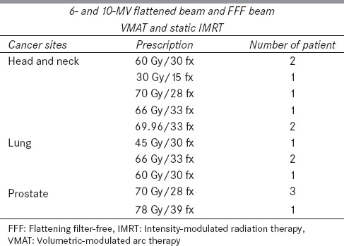
Fifteen anonymized patients with three anatomical cancer sites, such as head and neck, lung, and prostate, were randomly selected from the patient database in Human Oncology Department. A case number was assigned to refer to each anonymized patient. Clinical constrains for planning target volume (PTV) and OARs were obtained from the patients' medical document and were used for each patient to simulate the real treatment process. The dose prescriptions were selected from the typical dose range prescribed by the physicians. Dose prescription and patient information are summarized in Table 1.
Table 1.
Summary of cancer sites, beam energies, dose delivery techniques, dose prescriptions, and patient number used to design the treatment plans
Radiation therapy planning techniques
A Varian TrueBeam (Varian Medical Systems, Palo Alto, CA, USA) linac was commissioned on the Eclipse™ treatment planning system (TPS) (version 10.0, Varian Medical Systems, Palo Alto, CA). An anisotropic-analytical algorithm was used to calculate the dose for both static IMRT and VMAT plans. In this study, the static IMRT was based on the sliding window technique. The dose grid in the calculation was 2.5 mm for all plans. Photon beam energies of 6- and 10-MV were selected for this study. Beam modalities included flattened and FFF beams. All treatment parameters such as isocenter position, beam angle, arc number, and field size were set to be identical for the flattened and FFF beam plans in each case. High-definition 120-leaf multileaf collimator (MLC) (2.5 mm width in the center and 5 mm width in the peripheral) was used to generate all treatment plans.
For each patient, 8 treatment plans were generated, using 6- and 10-MV beams. Flattened and FFF static IMRT and flattened and FFF VMAT plans were created. In the FFF beam mode, the maximum dose rate varied from 600 MU/min to 1400 MU/min for 6 MV and from 600 to 2400 MU/min for 10 MV photon beam. For the VMAT plans with FFF beams, the TPS automatically selected the optimal dose rate during the optimization process. In our study, the optimal dose rates of the VMAT plans were lower than the maximum dose rates of the FFF beam for both energies. For treatment plans with large field sizes (e.g., ≈16 cm × 20 cm in case 2), the optimal dose rates of the VMAT plans were reduced (e.g., about 350 MU/min in case 2 for 6 MV beam) from the maximum dose rates of the FFF beam. For static IMRT plans, a constant dose rate of 600 MU/min was applied to design the treatment plans. This eliminated the influence of the speed limit of the MLC. For all treatment plans, the normal tissue falloff function, priority of each organ in the optimizer were set to be the same for all treatment plans in each case. The optimization processes were repeated 5 times for all static IMRT and VMAT plans to get an optimal dose distribution. To exclude the bias of treatment plan skills of different individuals in the final results, all treatment plans were designed by the same person.
Digital imaging and communications in medicine files from the Eclipse workstation were exported to the computational environment for radiotherapy research[31] to calculate dose-volume histogram (DVH). In-house developed MATLAB code (Math Works, Natick, MA, USA) was used to calculate the dose and to perform statistical analysis. The dosimetric results were benchmarked with the Eclipse software system for each case. All dosimetric parameters obtained from the two systems were in agreement.
Treatment plan evaluation
Target coverage (TC) and dose to OARs were analyzed to evaluate the treatment plans for all cases. For all treatment plans, 95% of the target volume was normalized to 95% of the dose prescription for evaluation and optimization. The criteria used to evaluate the TC included conformity index (CI), TC, conformity number (CN), and gradient index (GI). These are defined as:[32]
CI = TV95/PTV95 (1)
TC = PTV95/PTV (2)
CN = CI/TC (3)
GI = TV50/TV95 (4)
In equations 1-4, TV95 and PTV95 refer to the treated volume and the PTV covered by the 95% dose line, respectively. A value closer to one indicates better TC for all indices. A paired sample t-test[33] was applied to analyze the statistical differences of TC among patients (statistical significance, P ≤ 0.05).
Results
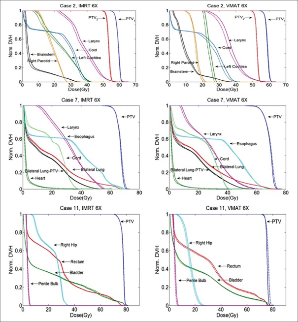
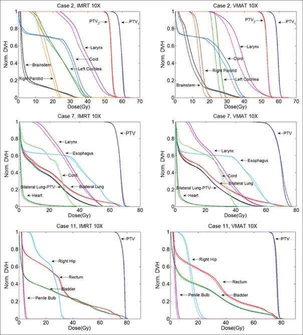
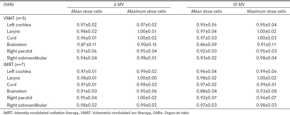
The DVHs of one patient showing the obvious differences between the flattened beam plans and the FFF beam plans are selected from each treatment site and are shown in Figures 1 and 2. In general, the FFF beam provided similar TC as the flattened beam. No significant difference (P ≫ 0.05) in TC was observed for head and neck cases. Among the three cancer sites, the dose sparing effect of the FFF beam is significant in head and neck cases. For certain OARs such as right parotid, left cochlea, larynx, and right submandibular gland, noticeable dose sparing effect is obtained by the FFF beam compared to the flattened beam. In Figures 1 and 2, for static IMRT plans, the FFF beam has the most significant dose sparing effect compared to the flattened beam on larynx and right submandibular gland. Compared to the flattened beam, the FFF beam reduces mean dose up to 2.05 Gy and 1.36 Gy for larynx and right submandibular, respectively, for 10 MV beam. For VMAT plans, left cochlea and larynx show the best dose sparing effect from the FFF beam compared to the flattened beam. The mean dose reductions are on the order of 2.36, 2.82 Gy, respectively. Compared with the static IMRT plans, the VMAT plans show considerable differences between the flattened beam and FFF beam. Relative dose ratio between the flattened beam and FFF beam for five head and neck cases is shown in Table 2. For right parotid, left cochlea, larynx, and right submandibular gland, the mean dose reduction of the FFF beam compared to the flattened beam reaches up to 9%, 5%, 3%, and 7%, for VMAT plans, respectively.
Figure 1.
Normalized treatment plans comparison between the flattened and the flattening filter-free beams for the static intensity-modulated radiation therapy and the volumetric-modulated arc therapy plans for 6 MV beam. Head and neck, lung, and prostate cases are shown. The solid lines are the flattened beam plans and the dashed lines are the flattening filter-free beam plans
Figure 2.
Normalized treatment plans comparison between the flattened and the flattening filter-free beams for the static intensity-modulated radiation therapy and the volumetric-modulated arc therapy plans for 10 MV beam. Head and neck, lung, and prostate cases are shown. The solid lines are the flattened beam plans and the dashed lines are the flattening filter-free beam plans
Table 2.
Relative dose ratio (flattening filter-free/flattened) to organ-at-risks for head and neck cases
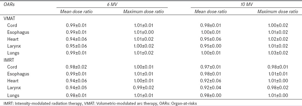
Significant differences (P < 0.05) between the flattened beam and FFF beam were observed for the VMAT plans in lung cancer cases. For VMAT plans, FFF beam provides a higher (1%) relative mean dose (Dmean/Dx) to the target compared with the flattened beam for both 6- and 10-MV beams. For the static IMRT plans, the difference between the flattened beam and FFF beam is not significant. For the lung cancer case, as shown in Figures 1 and 2, larynx has the most significant dose sparing effect from the FFF beam compared to the flattened beam, both for 10 MV static IMRT and VMAT plans. In Figures 1 and 2, the reduction in the mean dose for the FFF beam compared to the flattened beam is 1.6 Gy for larynx. For other organs, comparable doses are obtained by the FFF beam and flattened beam for static IMRT and VMAT plans in both beam energies. Relative dose ratio between the flattened beam and FFF beam for four lung cases is shown in Table 3. For organs such as heart and lungs, the FFF beam compared to flattened beam tends to provide higher maximum dose of 2% and 3%, respectively. This effect is more significant in 10 MV VMAT lung plans compared with the other three plans.
Table 3.
Relative dose ratio (flattening filter-free/flattened) to organ-at-risks for lung cases (n=4)
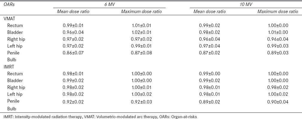
For the prostate cancer, the TC was similar to head and neck cases. No significant difference (P ≫ 0.05) in TC was observed between the flattened beam and FFF beam. For both VMAT and static IMRT plans, the FFF beam provides a comparable or improved dose sparing effect to OARs. The dose of a selected prostate case is shown in Figures 1 and 2. The maximum reduction in the mean dose is obtained for the right hip (1.03 Gy) in the 10 MV VMAT plan compared to the flattened beam. The relative dose ratios between the flattened beam and FFF beam for 4 prostate cancer patients are shown in Table 4. For rectum, in VMAT plans, the FFF beam provided slightly higher (1%) maximum dose compared to the flattened beam. For all OARs, the FFF beam provided improved dose sparing effect compared to the flattened beam.
Table 4.
Relative dose ratio (flattening filter-free/flattened) to organ-at-risks for prostate cases (n=4)
Discussion
Based on our investigation, we found that in terms of TC, the FFF beam provided similar TC as the flattened beam in most cases. The only difference was observed in the VMAT plans for lung cases. In terms of dose sparing to OARs, in head and neck cases, the differences between the FFF beam and flattened beam are significant for both 6- and 10-MV beams. For lung and prostate, results were comparable. Some head and neck cases required relatively larger field size (≈16 cm × 20 cm) to cover the target. For the VMAT plans, two arcs with different isocenters were used to provide the required dose coverage for the PTVs. In other cancer sites, typical field sizes (≈10 cm × 10 cm) were used to create the treatment plans.
The noticeable dose sparing effect of the FFF beam compared with the flattened beam for large treatment field size is due to the forward peak beam profiles of the FFF beam. There is no observable difference between the beam profiles of flattened beam and FFF beam for small field size (e.g. ≈6 cm × 6 cm). For relatively large field sizes (e.g. 16 cm × 20 cm), the FFF beam provided lower dose to the out-of-field region compared with the flattened beam for both 6- and 10-MV beams. This is of clinical significance for cases receiving a high radiation dose (~70 Gy) and having a diversity of sensitive normal tissue structures as found in the head and neck region. When we increased the beam energy from 6 MV to 10 MV, the dose reduction effect in the out-of-field region was significant for the FFF beam compared to the flattened beam.[22] This fact also explains the improved dose sparing effect of the FFF beam in head and neck cases in both 10 MV static IMRT and VMAT plans compared to the 6 MV plans.
However, due to the nonuniform beam profile of the FFF beam, compared to the flattened beam, the FFF beam tends to use more MUs to deliver the uniform dose to target. In our clinical investigation, the ratio of MUs between the FFF beam plans and the flattened beam plans was typically around 1.3 for the static IMRT and VMAT plans. The higher MUs of the FFF beam may lead to increased dose leakage from the MLC and escalated dose to OARs. Based on our investigation, even with the increased leakage dose from MLC, the FFF beam can still provide comparable dose sparing effect to OARs in most cases.
Randomized studies showed that compared to 3D-CRT technique, IMRT can dramatically reduce the dose to OARs, which leads to improved toxicity outcomes and quality of life for patients.[34,35,36] Despite these improvements, both acute and late toxicity represent ongoing challenges to successful head and neck cancer treatments. In the cases we examined, the lower dose to submandibular glands and parotid glands could contribute to lower xerostomia rates as the mean dose to each of these OARs has been directly associated with xerostomia.[37] In the dose range where xerostomia is likely to happen, a linear correlation with the mean dose is apparent, suggesting even modest dose improvement may have a clinical impact.[38] Other toxicities that may be affected include voice quality, swallowing function, breathing function, and cataract development. In head and neck, for both static IMRT and VMAT plans, the flattened beam and FFF beam provided improved dose sparing to right parotid gland and right submandibular gland. Clearly, the FFF beam provided a significant dose sparing effect to the right parotid and right submandibular gland compared to the flattened beam and should lead to a lower probability of xerostomia. The higher larynx dose associated with a flattened beam may contribute to poor voice quality as the larynx mean dose has been correlated with laryngeal edema.[39] The late toxicity of radiation treatment is directly related to both overall dose and dose per fraction. The lower mean and maximal doses achieved to OAR reduces both total delivered dose to several critical organs and the daily fraction size. Thus, FFF treatment for the examined head and neck cases may allow for the same local control with a decreased risk of late side effects of treatment.
The design of this study has several limitations. (1) To simulate the typical clinical treatment, three cancer sites with a total of 15 patients were selected for the study. A relative small number of patients was used for each cancer site. (2) Different prescribed doses were used to design the treatment plans, which make the statistical analysis such as t-test to be difficult for the dose sparing to OARs. For head and neck cases, 10 MV beam is not used for typical treatments. Further studies are needed to investigate the potential applications of the 10 MV FFF beam in clinical head and neck treatments.
Conclusion
In this work, 15 clinical cancer cases for three anatomical sites were investigated to analyze the dosimetric differences between the flattened and FFF beam plans in terms of TC and dose to OARs. It was observed that the FFF beam provides comparable TC to the flattened beam in all three sites of cancer. The FFF beam for head and neck cancer obtained observable dose sparing. For right parotid, the maximum mean dose reduction of the FFF beam compared to the flattened beam reached up to 9% for VMAT plans. For the other two sites, the FFF beam provided improved dose sparing effect to most of the OARs. For certain OARs such as heart in the VMAT plan for lung cancer, the FFF beam delivered higher maximum dose. Due to the speed limit of the MLC, the maximum dose rate of the FFF beam may be considerably lower than the theoretical maximum dose rate value, especially for large field sizes.
Financial support and sponsorship
Nil.
Conflicts of interest
There are no conflicts of interest.
Acknowledgements
Many thanks to Dr. Edward Bender and Dr. Bryan Bednarz in the University of Wisconsin, Madison for their enthusiastic discussion on flattened beam and the FFF beam.
References
- 1.Yu CX. Intensity-modulated arc therapy with dynamic multileaf collimation: An alternative to tomotherapy. Phys Med Biol. 1995;40:1435–49. doi: 10.1088/0031-9155/40/9/004. [DOI] [PubMed] [Google Scholar]
- 2.Mackie TR, Holmes T, Swerdloff S, Reckwerdt P, Deasy JO, Yang J, et al. Tomotherapy: A new concept for the delivery of dynamic conformal radiotherapy. Med Phys. 1993;20:1709–19. doi: 10.1118/1.596958. [DOI] [PubMed] [Google Scholar]
- 3.Cahlon O, Hunt M, Zelefsky MJ. Intensity-modulated radiation therapy: Supportive data for prostate cancer. Semin Radiat Oncol. 2008;18:48–57. doi: 10.1016/j.semradonc.2007.09.007. [DOI] [PubMed] [Google Scholar]
- 4.Followill D, Geis P, Boyer A. Estimates of whole-body dose equivalent produced by beam intensity modulated conformal therapy. Int J Radiat Oncol Biol Phys. 1997;38:667–72. doi: 10.1016/s0360-3016(97)00012-6. [DOI] [PubMed] [Google Scholar]
- 5.Cashmore J, Ramtohul M, Ford D. Lowering whole-body radiation doses in pediatric intensity-modulated radiotherapy through the use of unflattened photon beams. Int J Radiat Oncol Biol Phys. 2011;80:1220–7. doi: 10.1016/j.ijrobp.2010.10.002. [DOI] [PubMed] [Google Scholar]
- 6.Diallo I, Haddy N, Adjadj E, Samand A, Quiniou E, Chavaudra J, et al. Frequency distribution of second solid cancer locations in relation to the irradiated volume among 115 patients treated for childhood cancer. Int J Radiat Oncol Biol Phys. 2009;74:876–83. doi: 10.1016/j.ijrobp.2009.01.040. [DOI] [PubMed] [Google Scholar]
- 7.Ong CL, Dahele M, Slotman BJ, Verbakel WF. Dosimetric impact of the interplay effect during stereotactic lung radiation therapy delivery using flattening filter-free beams and volumetric modulated arc therapy. Int J Radiat Oncol Biol Phys. 2013;86:743–8. doi: 10.1016/j.ijrobp.2013.03.038. [DOI] [PubMed] [Google Scholar]
- 8.Georg D, Knöös T, McClean B. Current status and future perspective of flattening filter free photon beams. Med Phys. 2011;38:1280–93. doi: 10.1118/1.3554643. [DOI] [PubMed] [Google Scholar]
- 9.Huang Y, Siochi RA, Bayouth JE. Dosimetric properties of a beam quality-matched 6 MV unflattened photon beam. J Appl Clin Med Phys. 2012;13:3701. doi: 10.1120/jacmp.v13i4.3701. [DOI] [PMC free article] [PubMed] [Google Scholar]
- 10.Vassiliev ON, Titt U, Kry SF, Pönisch F, Gillin MT, Mohan R. Monte Carlo study of photon fields from a flattening filter-free clinical accelerator. Med Phys. 2006;33:820–7. doi: 10.1118/1.2174720. [DOI] [PubMed] [Google Scholar]
- 11.Reggiori G, Mancosu P, Castiglioni S, Alongi F, Pellegrini C, Lobefalo F, et al. Can volumetric modulated arc therapy with flattening filter free beams play a role in stereotactic body radiotherapy for liver lesions. A volume-based analysis? Med Phys. 2012;39:1112–8. doi: 10.1118/1.3679858. [DOI] [PubMed] [Google Scholar]
- 12.Titt U, Vassiliev ON, Pönisch F, Dong L, Liu H, Mohan R. A flattening filter free photon treatment concept evaluation with Monte Carlo. Med Phys. 2006;33:1595–602. doi: 10.1118/1.2198327. [DOI] [PubMed] [Google Scholar]
- 13.Ghahremani S, Chavez R, Li Y, Crownover R, Baacke D, Papanikolaou N, et al. SU-E-T-435: Flattening filter free beams for head and neck IMRT and VMAT optimization. Med Phys. 2015;42:3434. [Google Scholar]
- 14.Kry SF, Vassiliev ON, Mohan R. Out-of-field photon dose following removal of the flattening filter from a medical accelerator. Phys Med Biol. 2010;55:2155–66. doi: 10.1088/0031-9155/55/8/003. [DOI] [PubMed] [Google Scholar]
- 15.Kragl G, Baier F, Lutz S, Albrich D, Dalaryd M, Kroupa B, et al. Flattening filter free beams in SBRT and IMRT: dosimetric assessment of peripheral doses. Z Med Phys. 2011;21:91–101. doi: 10.1016/j.zemedi.2010.07.003. [DOI] [PubMed] [Google Scholar]
- 16.Tsiamas P, Seco J, Han Z, Bhagwat M, Maddox J, Kappas C, et al. A modification of flattening filter free linac for IMRT. Med Phys. 2011;38:2342–52. doi: 10.1118/1.3571419. [DOI] [PubMed] [Google Scholar]
- 17.Wang Y, Khan MK, Ting JY, Easterling SB. Surface dose investigation of the flattening filter-free photon beams. Int J Radiat Oncol Biol Phys. 2012;83:e281–5. doi: 10.1016/j.ijrobp.2011.12.064. [DOI] [PubMed] [Google Scholar]
- 18.Vassiliev ON, Titt U, Pönisch F, Kry SF, Mohan R, Gillin MT. Dosimetric properties of photon beams from a flattening filter free clinical accelerator. Phys Med Biol. 2006;51:1907–17. doi: 10.1088/0031-9155/51/7/019. [DOI] [PubMed] [Google Scholar]
- 19.Pönisch F, Titt U, Vassiliev ON, Kry SF, Mohan R. Properties of unflattened photon beams shaped by a multileaf collimator. Med Phys. 2006;33:1738–46. doi: 10.1118/1.2201149. [DOI] [PubMed] [Google Scholar]
- 20.Kragl G, Albrich D, Georg D. Radiation therapy with unflattened photon beams: Dosimetric accuracy of advanced dose calculation algorithms. Radiother Oncol. 2011;100:417–23. doi: 10.1016/j.radonc.2011.09.001. [DOI] [PubMed] [Google Scholar]
- 21.Stevens SW, Rosser KE, Bedford JL. A 4 MV flattening filter-free beam: Commissioning and application to conformal therapy and volumetric modulated arc therapy. Phys Med Biol. 2011;56:3809–24. doi: 10.1088/0031-9155/56/13/005. [DOI] [PubMed] [Google Scholar]
- 22.Chang Z, Wu Q, Adamson J, Ren L, Bowsher J, Yan H, et al. Commissioning and dosimetric characteristics of TrueBeam system: Composite data of three TrueBeam machines. Med Phys. 2012;39:6981–7018. doi: 10.1118/1.4762682. [DOI] [PubMed] [Google Scholar]
- 23.Hrbacek J, Lang S, Klöck S. Commissioning of photon beams of a flattening filter-free linear accelerator and the accuracy of beam modeling using an anisotropic analytical algorithm. Int J Radiat Oncol Biol Phys. 2011;80:1228–37. doi: 10.1016/j.ijrobp.2010.09.050. [DOI] [PubMed] [Google Scholar]
- 24.Kry SF, Titt U, Pönisch F, Vassiliev ON, Salehpour M, Gillin M, et al. Reduced neutron production through use of a flattening-filter-free accelerator. Int J Radiat Oncol Biol Phys. 2007;68:1260–4. doi: 10.1016/j.ijrobp.2007.04.002. [DOI] [PubMed] [Google Scholar]
- 25.Thomas EM, Popple RA, Prendergast BM, Clark GM, Dobelbower MC, Fiveash JB. Effects of flattening filter-free and volumetric-modulated arc therapy delivery on treatment efficiency. J Appl Clin Med Phys. 2013;14:4328. doi: 10.1120/jacmp.v14i6.4328. [DOI] [PMC free article] [PubMed] [Google Scholar]
- 26.Zhang GG, Ku L, Dilling TJ, Stevens CW, Zhang RR, Li W, et al. Volumetric modulated arc planning for lung stereotactic body radiotherapy using conventional and unflattened photon beams: A dosimetric comparison with 3D technique. Radiat Oncol. 2011;6:152. doi: 10.1186/1748-717X-6-152. [DOI] [PMC free article] [PubMed] [Google Scholar]
- 27.Nicolini G, Ghosh-Laskar S, Shrivastava SK, Banerjee S, Chaudhary S, Agarwal JP, et al. Volumetric modulation arc radiotherapy with flattening filter-free beams compared with static gantry IMRT and 3D conformal radiotherapy for advanced esophageal cancer: A feasibility study. Int J Radiat Oncol Biol Phys. 2012;84:553–60. doi: 10.1016/j.ijrobp.2011.12.041. [DOI] [PubMed] [Google Scholar]
- 28.Ong CL, Dahele M, Cuijpers JP, Senan S, Slotman BJ, Verbakel WF. Dosimetric impact of intrafraction motion during RapidArc stereotactic vertebral radiation therapy using flattened and flattening filter-free beams. Int J Radiat Oncol Biol Phys. 2013;86:420–5. doi: 10.1016/j.ijrobp.2012.12.028. [DOI] [PubMed] [Google Scholar]
- 29.Prendergast BM, Fiveash JB, Popple RA, Clark GM, Thomas EM, Minnich DJ, et al. Flattening filter-free linac improves treatment delivery efficiency in stereotactic body radiation therapy. J Appl Clin Med Phys. 2013;14:4126. doi: 10.1120/jacmp.v14i3.4126. [DOI] [PMC free article] [PubMed] [Google Scholar]
- 30.Vassiliev ON, Kry SF, Kuban DA, Salehpour M, Mohan R, Titt U. Treatment-planning study of prostate cancer intensity-modulated radiotherapy with a Varian Clinac operated without a flattening filter. Int J Radiat Oncol Biol Phys. 2007;68:1567–71. doi: 10.1016/j.ijrobp.2007.04.025. [DOI] [PubMed] [Google Scholar]
- 31.Deasy JO, Blanco AI, Clark VH. CERR: A computational environment for radiotherapy research. Med Phys. 2003;30:979–85. doi: 10.1118/1.1568978. [DOI] [PubMed] [Google Scholar]
- 32.Dhabaan A, Elder E, Schreibmann E, Crocker I, Curran WJ, Oyesiku NM, et al. Dosimetric performance of the new high-definition multileaf collimator for intracranial stereotactic radiosurgery. J Appl Clin Med Phys. 2010;11:3040. doi: 10.1120/jacmp.v11i3.3040. [DOI] [PMC free article] [PubMed] [Google Scholar]
- 33.Student. The probable error of a mean. Biometrika. 1908;6:1–25. [Google Scholar]
- 34.Kam MK, Leung SF, Zee B, Chau RM, Suen JJ, Mo F, et al. Prospective randomized study of intensity-modulated radiotherapy on salivary gland function in early-stage nasopharyngeal carcinoma patients. J Clin Oncol. 2007;25:4873–9. doi: 10.1200/JCO.2007.11.5501. [DOI] [PubMed] [Google Scholar]
- 35.Pow EH, Kwong DL, McMillan AS, Wong MC, Sham JS, Leung LH, et al. Xerostomia and quality of life after intensity-modulated radiotherapy vs. conventional radiotherapy for early-stage nasopharyngeal carcinoma: Initial report on a randomized controlled clinical trial. Int J Radiat Oncol Biol Phys. 2006;66:981–91. doi: 10.1016/j.ijrobp.2006.06.013. [DOI] [PubMed] [Google Scholar]
- 36.Nutting CM, Morden JP, Harrington KJ, Urbano TG, Bhide SA, Clark C, et al. Parotid-sparing intensity modulated versus conventional radiotherapy in head and neck cancer (PARSPORT): A phase 3 multicentre randomised controlled trial. Lancet Oncol. 2011;12:127–36. doi: 10.1016/S1470-2045(10)70290-4. [DOI] [PMC free article] [PubMed] [Google Scholar]
- 37.Little M, Schipper M, Feng FY, Vineberg K, Cornwall C, Murdoch-Kinch CA, et al. Reducing xerostomia after chemo-IMRT for head-and-neck cancer: Beyond sparing the parotid glands. Int J Radiat Oncol Biol Phys. 2012;83:1007–14. doi: 10.1016/j.ijrobp.2011.09.004. [DOI] [PMC free article] [PubMed] [Google Scholar]
- 38.Anand AK, Jain J, Negi PS, Chaudhoory AR, Sinha SN, Choudhury PS, et al. Can dose reduction to one parotid gland prevent xerostomia.– A feasibility study for locally advanced head and neck cancer patients treated with intensity-modulated radiotherapy? Clin Oncol (R Coll Radiol) 2006;18:497–504. doi: 10.1016/j.clon.2006.04.014. [DOI] [PubMed] [Google Scholar]
- 39.Sanguineti G, Adapala P, Endres EJ, Brack C, Fiorino C, Sormani MP, et al. Dosimetric predictors of laryngeal edema. Int J Radiat Oncol Biol Phys. 2007;68:741–9. doi: 10.1016/j.ijrobp.2007.01.010. [DOI] [PubMed] [Google Scholar]


