Abstract
Building modelers need simulation tools capable of simultaneously considering building energy use, airflow and indoor air quality (IAQ) to design and evaluate the ability of buildings and their systems to meet today’s demanding energy efficiency and IAQ performance requirements. CONTAM is a widely-used multizone building airflow and contaminant transport simulation tool that requires indoor temperatures as input values. EnergyPlus is a prominent whole-building energy simulation program capable of performing heat transfer calculations that require interzone and infiltration airflows as input values. On their own, each tool is limited in its ability to account for thermal processes upon which building airflow may be significantly dependent and vice versa. This paper describes the initial phase of coupling of CONTAM with EnergyPlus to capture the interdependencies between airflow and heat transfer using co-simulation that allows for sharing of data between independently executing simulation tools. The coupling is accomplished based on the Functional Mock-up Interface (FMI) for Co-simulation specification that provides for integration between independently developed tools. A three-zone combined heat transfer/airflow analytical BESTEST case was simulated to verify the co-simulation is functioning as expected, and an investigation of a two-zone, natural ventilation case designed to challenge the coupled thermal/airflow solution methods was performed.
Keywords: building simulation; co-simulation; CONTAM; coupled thermal, airflow and contaminant modeling; EnergyPlus; multizone modeling
1. Introduction
Green and sustainable building programs and standards, e.g., (USGBC 2013; ASHRAE 2014), are helping to support the trend towards low energy buildings, and the manner in which they consider indoor air quality (IAQ) is critical to achieving energy efficient buildings with good indoor environments. While energy efficiency and IAQ are sometimes viewed as contradictory goals, integrated design processes and building systems can lead to high performing buildings that are both energy efficient and have good IAQ (Persily and Emmerich 2012). Modeling and simulation tools can improve the abilities of designers to achieve coordinated and integrated systems. For example, passive design features, i.e. the architectural and envelope aspects, can be optimized to reduce the need for active design strategies, i.e., heating ventilating and air-conditioning (HVAC) systems, for thermal conditioning. Source control can be implemented to reduce contaminant levels inside buildings thus reducing the energy consumption associated with removal via ventilation and air cleaning. More advanced building modeling capabilities, such as will be presented herein, could also account for interactions among building temperature, humidity, airflow and contaminant concentrations, and thus facilitate advanced HVAC system design including natural and hybrid ventilation and demand controlled ventilation.
1.1 CONTAM and EnergyPlus
CONTAM is a widely-used multizone (or nodal) building airflow and contaminant transport simulation tool that requires indoor temperatures as input values. EnergyPlus is a prominent whole-building energy simulation program capable of performing heat transfer calculations that require interzone and infiltration airflows as input values. Both programs are available in the public domain. On their own, each tool is limited in its ability to account for thermal processes upon which building airflow may be significantly dependent and vice versa. Recent advances in both EnergyPlus and CONTAM have been made that enable co-simulation between them.
CONTAM is used for predicting airflows, contaminant concentrations, and personal exposures in buildings (Dols and Polidoro 2015). Applications include designing ventilation and smoke control systems (Miller 2011), analyzing building vulnerability to airborne chemical and biological threats (Persily et al. 2007), assessing indoor air quality (Ng et al. 2012; Rim et al. 2013) and estimating infiltration airflows impacting building energy use (Emmerich et al. 2007; Villi et al. 2012; Han et al. 2015). The CONTAM transport model treats a building as a system of interdependent nodes (or zones) that store air and contaminant mass and transport elements that carry mass between the nodes. Interzone and infiltration airflows are determined by calculating the interior zone pressures that satisfy mass balance in each zone based on driving forces and boundary conditions that include HVAC system airflows as well as wind and stack pressures exerted on the building envelope.
EnergyPlus is a whole building energy simulation program with a multizone heat balance as its underlying building energy modeling calculation method (Crawley et al. 2001). EnergyPlus determines zone thermal loads and the energy required from the HVAC systems to balance those loads. It calculates resulting zone temperatures based on current system and plant capacity including system airflow rates. Generally, infiltration and interzone airflows are user-specified, i.e., not pressure-dependent as in CONTAM, and are not required to be in balance with system airflow rates. However, a limited network airflow solver (AFN) is implemented within EnergyPlus that allows for calculation of pressure-dependent, interzone airflows for a limited air distribution configuration (DOE 2014a). AFN is based on the AIRNET program (Walton 1989), which was a predecessor to and provides a subset of the capabilities of the airflow network solver implemented by CONTAM. Other recent modification have addressed the potential for flow imbalance to some degree (DOE 2014b), but these modifications are not pressure-dependent.
With respect to airflow analysis, CONTAM provides the following advantages over EnergyPlus:
a larger set of air leakage component models
ability to define multiple airflow leakage points within a given surface where EnergyPlus requires a one-to-one correspondence between heat transfer surfaces and air leakage components
the ability to define complex duct systems with multiple fan configurations
a freely available graphical user interface that enables development of very, large complex building configurations
With respect to contaminant transport analysis, CONTAM provides the following advantages over EnergyPlus:
ability to account for a practically unlimited number of contaminants, sources and sinks within a given building model
a richer set of source and sink models including deposition with resuspension
contaminant filters including ultra-violet germicidal irradiation (UVGI)
one-dimensional convection/diffusion transport in zones and ducts
a coupled zero-order turbulence computational fluid dynamics model
While, for the sake of brevity, emphasis is placed on the combined energy and airflow aspects of the coupling, the contaminant transport aspects of CONTAM are still readily available under this coupling scheme. These contaminant transport aspects are fully addressed in the CONTAM documentation (Dols and Polidoro 2015) and have been widely applied in the literature. Dols, Emmerich, et al. (2015) present a similar application of coupling between CONTAM and the TRNSYS building energy analysis program (Duffy et al. 2009) and discuss various aspects of contaminant transport coupling that also apply to the coupling described herein.
The coupling of building energy and airflow analysis has been discussed previously (Walton 1982; Axley and Grot 1989; Wang et al. 2012). Axley and Grot (1989) present multiple methods for addressing the solution of coupled methods including those referred to as quasi-dynamic and dynamic coupling. These methods are also referred to as: ping-pong and onion coupling, respectively; and loose and strong coupling, respectively (Hensen 1999). Dynamic coupling provides iteration and data exchange between program modules to be closely monitored and step-wise adjustments or relaxation factors to be applied to control oscillation of the numerical approximation to the solution. This tight coupling requires direct access to and modification of the program code. Modelling domains can also be loosely coupled using co-simulation techniques whereby the solution of each domain is handled separately, and the exchange of data is coordinated according to pre-arranged methods of interfacing the subsystems or programs (Nouidui et al. 2014). Both methods have benefits and drawbacks as discussed in several of the aforementioned references, and a historical perspective and overview are presented in Dols, Wang, et al. (2015).
1.2 Mathematical Description
In the case of co-simulation between EnergyPlus and CONTAM, both programs address the behavior of whole building systems. EnergyPlus is best suited to address the building energy aspects, while CONTAM more fully addresses the pressure-driven airflow and contaminant transport aspects of building systems. We address herein the coupling between the energy balance equations of EnergyPlus and the mass balance of airflows in ContamX according to equations (1) and (2) respectively.
| (1) |
| (2) |
where
| (3) |
Equations (1) and (2) are applied for all zones (nodes) of the building models. According to Nouidui et al. (2014), the co-simulation capabilities of EnergyPlus enable coupling of the differential variable of the EnergyPlus model, Tz in this case, with either a differential or algebraic variable of the coupled model, ṁ in this case. Note that the dependency of airflow on Tz occurs through the functions of equation (3) that relate mass flow rate to air density which is in turn dependent on zone temperature. The first and second terms of equation (1) include interzone mass airflows in the form of volumetric airflow rates multiplied by the average density of air flowing into a zone, ρavgqi, and directly in the form of an infiltration mass airflow rate, ṁinf. These mass airflow rates will be determined by CONTAM while the temperatures will be determined by EnergyPlus. The Q̇sys term inherently includes the HVAC system airflow rates, and these are determined by EnergyPlus based on the thermal load, and passed to CONTAM along with the zone temperatures.
1.3 Co-Simulation
Co-simulation is a technique that allows individual component models described by differential, algebraic or discrete equations to be simulated by different simulation programs running simultaneously and exchanging data that depend on state variables during run-time (Nouidui et al. 2014). Co-simulation allows one to subdivide a building into different domains and then model each domain using the simulation tool which is best suited for the problem at hand. Further, co-simulation allows for coupling between tools that are developed independently of one another. For the purposes of the co-simulation presented herein, the CONTAM domain includes the calculation of interzone and infiltration airflows and contaminant transport while the EnergyPlus domain includes the energy balance and determination of HVAC system airflow rates.
Nouidui et al. (2014) and Nouidui et al. (2013) describe the development and implementation of a Functional Mock-up Unit (FMU) for co-simulation import interface in EnergyPlus which allows EnergyPlus to conduct co-simulation with various other simulation programs that are packaged as FMUs according to the Functional Mock-up Interface (FMI) specification for co-simulation version 1.0 (MODELISAR 2010). Nouidui et al. (2014) describe three approaches for co-simulation using EnergyPlus:
One-to-one coupling – communication between EnergyPlus and the second model is accomplished through specific interfaces implemented in both programs
Middleware coupling – a third program implements a co-simulation master algorithm that coordinates the two simulation programs and manages the data exchange between them
Standardized co-simulation interface – communication is accomplished through a standard interface for co-simulation which is implemented in both programs
Past co-simulation efforts using EnergyPlus have included coupling with a computational fluid dynamics (CFD) tool (Zhai and Chen 2005), Matlab, Simulink, Radiance and Modelica (Nouidui et al. 2014; Wetter 2011; Chen et al. 2015) among others.
The FMI implementation of EnergyPlus version 8.3 does not provide for dynamic coupling (Nouidui et al. 2014), so the current EnergyPlus/CONTAM coupling implements the quasi-dynamic method. Dynamic coupling is, for the same synchronization time step length, more accurate than quasi-dynamic coupling due to synchronization of the common variables at each time step, but it is typically more computationally expensive and prone to convergence issues. The quasi-dynamic method requires shorter time steps to prevent stability issues. These instabilities arise when utilizing explicit solution techniques to which this coupling method is related due to the sequential nature of the execution of the separate programs and the lagging in time of the exchange state variables between programs during co-simulation. These convergence and stability issues are presented in some of the aforementioned references including potential numerical reasons (Lorenzetti 2002; Weber et al. 2003) and situations in which these issues may arise (Li and Delsante 2001; Li et al. 2001; Axley et al. 2002). Trcka et al. (2009) provide an evaluation of co-simulation using both dynamic and quasi-dynamic coupling and various methods of partitioning the coupling data among the processes.
2. EnergyPlus/CONTAM Coupling Approach
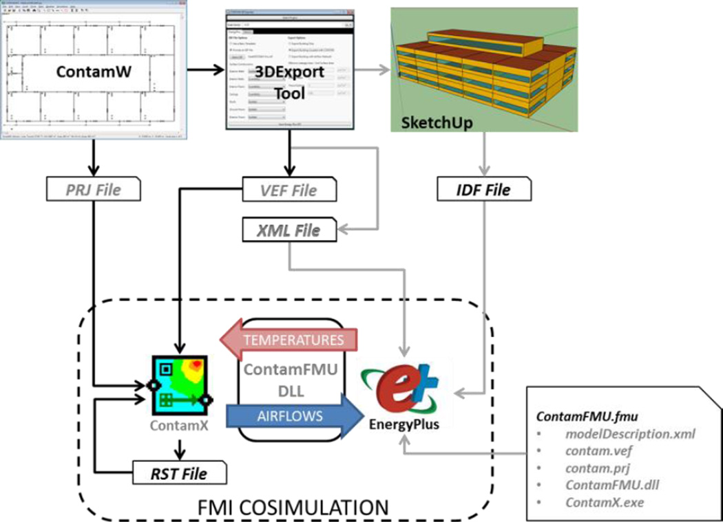
New and existing software tools have been developed or modified in order to facilitate the synchronization of building representations and dynamic data exchange between EnergyPlus and CONTAM. The relationship between the components utilized during an EnergyPlus/CONTAM co-simulation are presented in Figure 1. The CONTAM graphical user interface, ContamW, was modified to enable creation of project files (PRJ files) that provide scaled rectilinear representations of building floor plans. A newly developed Contam3DExporter tool reads in the PRJ file and creates an EnergyPlus input data file (IDF file) along with files that contain data exchange parameters to be used during the co-simulation by both EnergyPlus and CONTAM (XML and VEF files). The IDF file can be viewed and edited via SketchUp software with an OpenStudio plugin (NREL 2016). The CONTAM simulation engine, ContamX, has been modified to provide a set of execution control and data transfer messages to enable compatibility with the EnergyPlus heat balance model and to utilize a simulation restart file (RST file) that enables one-day simulations to be performed in coordination with EnergyPlus warm-up days. A new Windows dynamic link library (ContamFMU.dll) was developed to provide an application programming interface (API) based on the FMI for Co-Simulation specification version 1.0 (MODELISAR 2010). ContamFMU.dll manages the exchange of data and execution control commands between EnergyPlus and ContamX during a coupled simulation. The Contam3DExporter packages the necessary files into an FMU file (ContamFMU.fmu) as required by the FMI specification.
Figure 1.
Schematic of relationship between EnergyPlus/CONTAM co-simulation components.
The CONTAM3DExporter creates an IDF file that contains objects associated with the geometry, infiltration airflow, inter-zone or mixing airflows, HVAC system airflows, and FMI-related entities required to facilitate dynamic data exchange. Currently, the following data can be exchanged between EnergyPlus and ContamX, including and in addition to the temperatures and airflows depicted in Figure 1:
- From EnergyPlus to ContamX
-
◦Zone Temperatures
-
◦Ventilation system airflows for zone supply and return airflows
-
◦Outdoor airflow fractions of outdoor airflow controllers
-
◦Exhaust fan airflows
-
◦Outdoor environment data including temperature, barometric pressure, wind speed and wind direction
-
◦Output variables user-selected from numerous EnergyPlus output variables
-
◦
- From ContamX to EnergyPlus
-
◦Zone infiltration airflows
-
◦Inter-zone airflows
-
◦Controls values user-defined values exposed via the CONTAM controls network, e.g., a signal calling for ventilation airflow due to an elevated contaminant level
-
◦
Detailed mappings between CONTAM and EnergyPlus entities are provided in the CONTAM documentation (Dols and Polidoro 2015). These data are exchanged in the direction indicated in the list below at each synchronization time step. The ContamFMU performs a check at the beginning of the simulation to ensure that the time steps of both EnergyPlus and CONTAM are compatible.
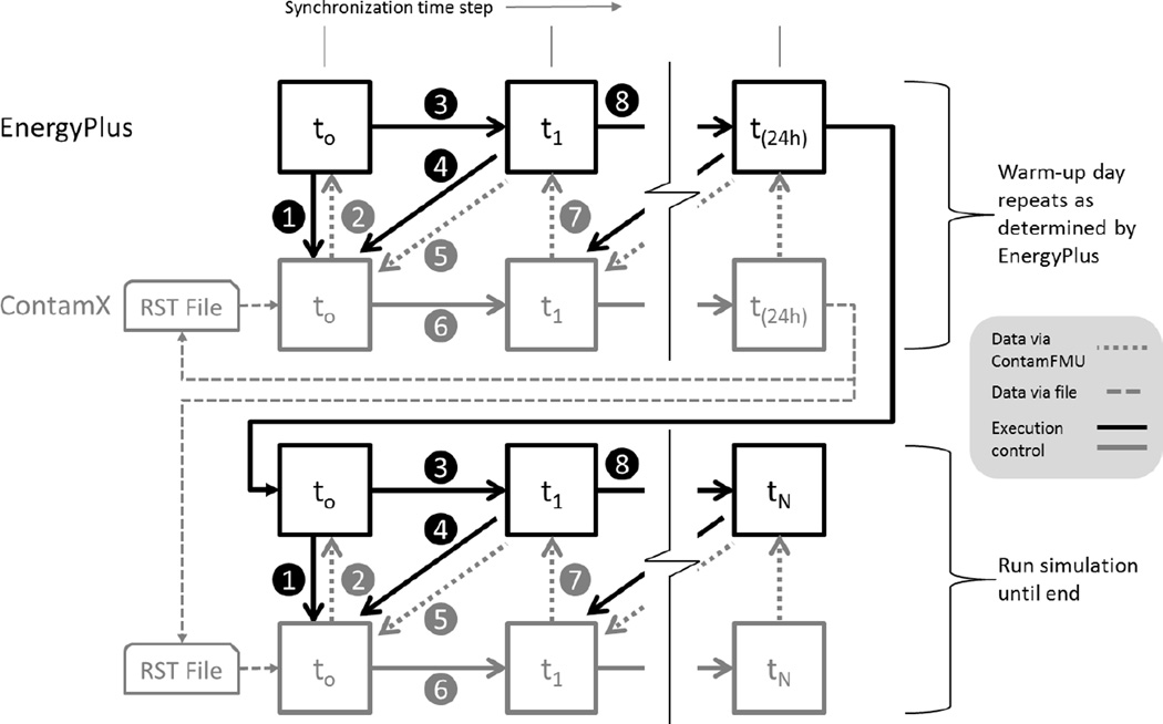
In the co-simulation between EnergyPlus and CONTAM, EnergyPlus implements a co-simulation master algorithm and ContamFMU is a slave process. Therefore, this coupling process is a hybrid of the so-called middleware coupling and standardized co-simulation interface coupling described above. While ContamFMU implements an API based on the FMI specification, ContamX itself does not. Previous versions of ContamX already implemented a set of execution control and data exchange messages utilizing socket communication, and other programs utilize this coupling capability (Dols, Wang, et al. 2015; Bonan et al. 2014; Herring et al. 2014). For the time being, rather than implement ContamX as an FMU directly, we leveraged existing capabilities and minimized modifications to the ContamX code.
The quasi-dynamic coupling scheme is illustrated in Figure 2. The figure depicts data exchange and program execution flow control via the dashed and solid arrows, respectively. EnergyPlus utilizes warm-up days at the beginning of a simulation in order to allow the first day of the simulation to “stabilize” with respect to maximum and minimum zone temperatures and heating and cooling loads. During this warm-up process, ContamX utilizes a project-specific restart file (RST file) to initialize values to those at the end of the previously run warm-up day. In this manner, the temperatures and airflow rates at the beginning of the full simulation start off with stable values.
Figure 2.
Schematic of quasi-dynamic simulation scheme between EnergyPlus and ContamX.
(Sturler et al. 2000) refers to the “Correct Data Exchange Principle,” which states that data exchanged between processes should be done so in a “physics-aware fashion.” For example, ContamX performs interzone and infiltration airflow calculations based on mass airflows, while EnergyPlus utilizes volume airflows converted to mass flow rates based on the average zone temperatures for mixing flows (DOE 2014b, p. 458) and the destination zone temperature for infiltration flows. This is indicated by the ρavg term in equation (1). Therefore, ContamX mass airflow rates must be converted to volume flow rates according to the EnergyPlus density calculation method using the appropriate temperatures. ContamFMU also combines the airflows of multiple paths that connect the same two zones into “connections” and accounts for the total flows in each direction between the zones to provide EnergyPlus with interzone mixing airflows and total zone infiltration airflows.
3. Verification of Coupling Approach
In order to verify that the coupling approach as implemented to date is functioning as expected, a set of verification tests were developed and implemented. These cases are meant to establish several aspects of the coupling approach including:
data transfer between simulation units, i.e., EnergyPlus and CONTAM, is taking place as expected;
simulation results match those of the combined heat transfer/airflow analytical test case; and
performance of the quasi-dynamic coupling method.
Two cases are presented. The first is a three-zone, analytical case that demonstrates the use of an air handling system to drive airflow through three zones in series. It demonstrates the first two of the afore-mentioned aspects of verification. The second case is based on that presented by Wang et al. (2012) and is provided in the form of an inter-model comparison between this FMI-based coupling approach and the EnergyPlus AFN model currently implemented in EnergyPlus (version 8.3).
While this verification is an important step in establishing proper performance of the coupling approach for the cases addressed herein, it is not meant to imply that this coupling approach will be able to accurately address any and all thermal/airflow problems. The quasi-dynamic implementation is limited by the size of the smallest available synchronization time step. EnergyPlus has the limiting minimum synchronization time step of 60 seconds compared to one second of CONTAM. We present the afore-mentioned inter-model comparison to address the limitations in this quasi-dynamic coupling approach including instabilities that may arise and the ensuing behavior under various problem configurations and synchronization time steps.
3.1 Analytical Test Case
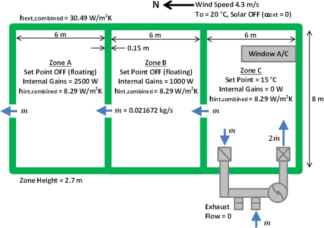
The verification test case presented here is based on a suite of Building Energy Simulation Tests (BESTEST) developed under the International Energy Agency (IEA) Task 34/Annex 43, specifically the multizone case MZ320 (Neymark and Judkoff 2008). Case MZ320, illustrated in Figure 3, is a three zone model having one zone cooled to a constant temperature below that of the outdoor temperature. Convective heat transfer coefficients are set to constant values and solar radiation effects are inactive. The original case includes conduction heat transfer but no interzone airflow.
Figure 3.
Plan View of Case MZ320 modified to include ventilation system and interzone airflow.
An analytical solution for a steady, annual simulation is presented by Neymark and Judkoff (2008). However, this case has been modified to include convective heat transfer attributed to interzone airflows driven by forced ventilation. The problem is represented by the following set of heat balance equations for the three zones, A, B and C, which can be solved for the three unknowns TA, TB and Q̇C.
| (4) |
| (5) |
| (6) |
Solving these equations analytically yields values for TA, TB and Q̇C of 30.31 ° C, 23.95 ° C, and 1,600 W (50.47 GJ for the entire year), respectively.
3.1.1 CONTAM and EnergyPlus Models
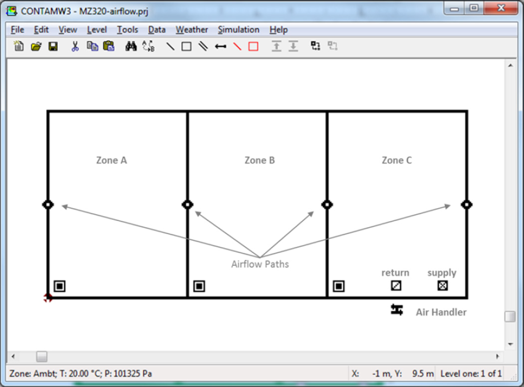
The CONTAM model shown in Figure 4 is drawn to scale and includes an air handling system with a supply and return located in zone C. This model was processed using the CONTAM3DExporter to create the associated three-dimensional EnergyPlus IDF file and FMU for co-simulation. The airflow paths are defined as orifices of 5 cm2/m2 of leakage area having discharge coefficients of 0.6 and exponent of 0.5. In order to drive airflow from zone C through zones A and B, the supply airflow to zone C must be greater than the return airflow from zone C and the leakage path between zone C and ambient was kept closed.
Figure 4.
ContamW representation of MZ320 with airflow.
The EnergyPlus model created by CONTAM3DExporter includes an HVAC system (HVACAirLoop object) that provides for airflow to and from zone C via a constant volume fan set to provide one air change per hour of supply air (0.036 m3/s). EnergyPlus IDF file was modified to incorporate energy-related components and properties using the EnergyPlus IDF Editor. Thermal conductivity of the exterior and interior walls were defined to be 0.24 W/m2·K and 1.24 W/m2·K, respectively. The outside boundary condition of all exterior walls was set to “Outdoors”, “NoSun” and “NoWind” and constant combined convection coefficients were set to 8.29 W/m2·K and 30.49 W/m2·K for all interior and exterior surfaces, respectively. Space conditioning was implemented by adding a window air-conditioner and thermostat to zone C with a 15 °C setpoint temperature. Temperatures of zones A and B were allowed to float, and heat gains were added to both zones as indicated in Figure 3.
For this coupling method, HVAC system flows are determined by EnergyPlus and ContamX determines zone mass balances. In order to achieve an imbalance between supply and return airflows of zone C in EnergyPlus, a zone exhaust fan was added, and the fan exhaust airflow rate was set to one half that of the system supply airflow rate (0.018 m3/s). The “Balanced Exhaust Fraction Schedule” of the zone exhaust fan was set to zero to reduce the return airflow of the EnergyPlus HVAC system by an amount equal to the unbalanced exhaust airflow rate. The EnergyPlus HVAC system flows (zone supply, zone return, system outdoor air intake and system outdoor air fraction) are provided to the CONTAM air handling system model. The imbalance in system flows drives the interzone airflow in the CONTAM model.
3.1.2 Results
As shown in Table 1 the resultant annual simulation values were within less than one-tenth of a percent of those of the analytical values. These include zone temperatures and annual sensible cooling energy supplied by the window air conditioner to maintain the setpoint temperature in zone C. CONTAM airflow results also matched the anticipated airflow rates of the ventilation system flows and the interzone flows. These results demonstrate proper exchange of simulation data in both directions between EnergyPlus and ContamX via FMI-based co-simulation.
Table 1.
Simulation results for analytical test case.
| Zone Air Temperature [°C] | Annual Cooling Load (GJ) |
|||
|---|---|---|---|---|
| Zone A | Zone B | Zone C | ||
| Analytical | 30.309 | 23.952 | 15.000 | 50.470 |
| Simulation | 30.310 | 23.953 | 15.000 | 50.476 |
3.2 Inter-model Comparison between AFN and FMU
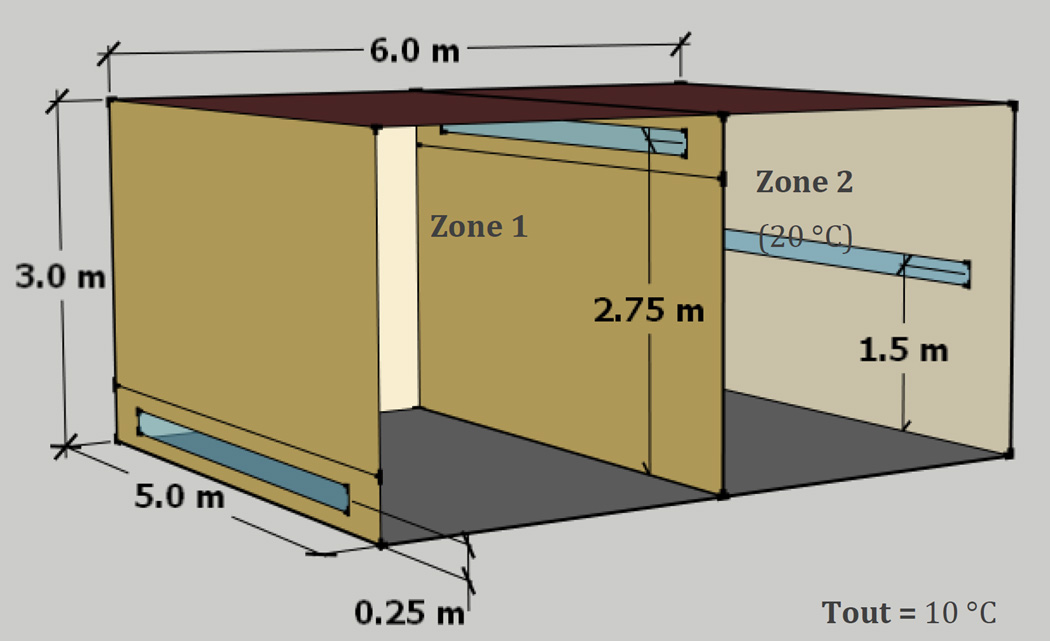
This FMI-based co-simulation between EnergyPlus and CONTAM is a quasi-dynamic method. As previously discussed, quasi-dynamic coupling between building energy and airflow has been demonstrated in various forms. The following inter-model comparison is meant to provide context to the current capabilities available to perform this coupling that is not widely available in public domain tools. This case was simulated using the AFN model of EnergyPlus (Gu 2007) and the EnergyPlus/CONTAM FMU co-simulation capabilities. It is a two-zone model that utilizes differences in zone temperatures to generate stack-driven airflow between zones including ambient. As shown in Figure 5, each zone is 45 m3 in volume and the opening locations are shown. This problem configuration was utilized to demonstrate the challenges inherent to quasi-dynamic coupling related to synchronization step size similar in nature to limitations of explicit numerical solution techniques for ODEs. Airflow through larger openings is more sensitive to changes in pressure difference across them. This is not to say that airflow through larger openings cannot be solved using explicit or quasi-dynamic simulation methods, but that these larger openings are meant to expose these limitations within the current range of available synchronization time steps of the coupled programs.
Figure 5.
Sketchup drawing of two-zone test case.
3.2.1 CONTAM and EnergyPlus Models
A CONTAM model was created and processed with CONTAM3DExporter. The EnergyPlus IDF file was then modified to implement the EnergyPlus AFN model with airflow paths as depicted schematically (i.e., scaled representation of a point-source opening having no defined shape within the models) in Figure 5. All walls were defined to have a thermal conductivity of 0.146 W/m·K with interior and exterior surface convection coefficients of 11 W/m2·K and 64 W/m2·K, respectively.
The generic, CONTAM power-law model as utilized by Wang et al. (2012) was converted to an equivalent effective leakage area model for use in both CONTAM and EnergyPlus, with an effective leakage area of 7,042 cm2, exponent of 0.6 and reference pressure of 4 Pa. This is equivalent to a normalized envelope leakage rate of approximately 633 m3/h·m2 at 75 Pa (117.5 cm2/m2) with respect to the six-sided building envelope surface area of 126 m2. The opening through the interior wall was defined to be the same size as the envelope openings, i.e., to provide the same resistance to airflow as each of the envelope openings.
In all, three different leakage rates were considered: the aforementioned baseline value and both an order-of-magnitude lower and higher leakage rate of 63.3 m3/h·m2 and 6330 m3/h·m2 at 75 Pa, respectively. The case of the order-of-magnitude lower envelope leakage rate corresponds to the higher end of measured commercial building envelope leakage rates as reported in Emmerich and Persily (2014), which indicates a maximum reported value of 77.9 m3/h·m2. While the order-of-magnitude higher leakage rate corresponds to an inordinately large opening, it reveals interesting behavior of the solution method.
3.2.2 Results
The simulation was run for two days, during which the ambient temperature was held constant at 10 °C and Zone 2 at 20 °C (using the EnergyPlus IdealLoadsAirSystem). Zone 1 was also held constant at 20 °C during the initial warm-up day to establish steady state initial conditions. During this first day, the stack conditions cause air to flow from ambient into Zone 1 through Zone 2 then back out to ambient, i.e., left-to-right in Figure 5.
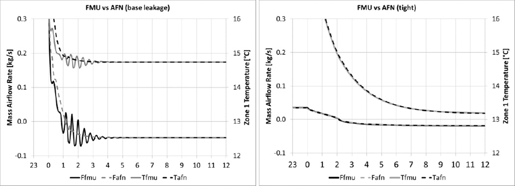
On the second day, the IdealLoadsAirSystem of Zone 1 was deactivated. As shown in Figure 6 (lines labeled “fmu” and “afn”), for the case with the baseline openings using a 5 minute synchronization time step, the temperature in Zone 1 begins to drop very quickly due mostly to convective heat transfer of air flowing through Zone 1 at approximately 23 h−1 via the fairly large openings and the initial inside-outside temperature difference of 10 °C.
Figure 6.
Results of two-zone case for base (left) and tight (right) leakage areas using a 300 s simulation time step.
Instability in the airflow and temperature begin to appear when the temperature in Zone 1 approaches that at which the stack pressures of all openings balance. The temperature at which the stack pressures balance is a function of opening height and zone air density. Since the temperatures in both the ambient and Zone 2 are held constant the stack-balance temperature of Zone 1 is readily calculated to be 14.91 °C. In this case, as the temperature continues to decrease, the direction of airflow reverses and the instabilities disappear. The oscillations were less significant for the AFN case. This is likely due to the coupling method employed by EnergyPlus between the heat balance and the AFN calculations. Gu (2007) indicates that within a system time step AFN interacts with the HVAC system iteratively until the differences between two iterations are less than some convergence tolerance. This indicates that this coupling is of the dynamic type. However, details of the simulation output revealed that there were occasions during the simulation when the AFN solver time step reduced automatically from 300 seconds (zone time step) to a shorter, variable time step (system time step). At no time during these simulations did multiple iterations, characteristic of dynamic coupling, occur between the heat balance and AFN solvers within a simulation time step. Although oscillations disappeared in this case, the conditional stability of these coupling methods does not guarantee this will always be the case as demonstrated later in this section.
Figure 6 also shows the cases with the lower leakage rate (tight) using a 300 second time step. In these cases the airflow and temperature of Zone 1 transition through the region of flow reversal with no oscillations for both the FMU and AFN solution methods. This reveals that this coupling method is applicable for addressing infiltration-based analysis or natural ventilation strategies that employ engineered openings such as trickle ventilators as opposed to those employing large openings. Because this coupling method is explicit in nature, these large openings will be better addressed using smaller synchronization time steps.
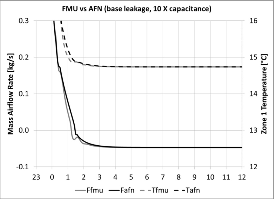
Actual buildings typically contain more thermal mass in the form of building furnishings and interior contents than this demonstration case. This is addressed in section 8.8.2 of ASHRAE Standard 90.2 (ANSI/ASHRAE 2007) which indicates that thermal mass may be on the order of ten times that of air. EnergyPlus provides a zone capacitance multiplier that can be used to account for increased zone capacitance, and the results of a simulation using a multiplier of 10 are shown in Figure 7. This capacitance acts as a damping mechanism and improves the stability of the explicit solution method by allowing for longer time steps (Taylor et al. 1990).
Figure 7.
Results of two-zone case with base leakage area, 300 s time step, and a zone thermal capacitance multiplier of 10.
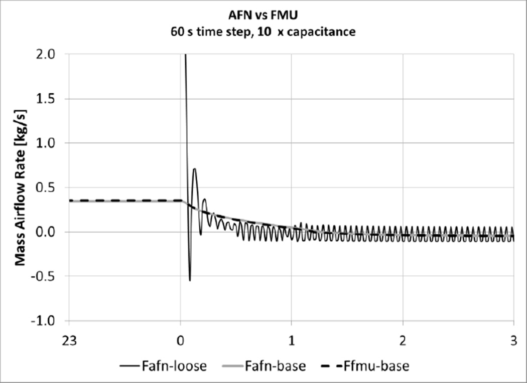
Figure 8 provides a comparison between the baseline leakage rate (base) and the higher leakage rate (loose) using the smallest allowable synchronization time step permissible by EnergyPlus of 60 seconds and a zone capacitance multiplier of 10. For the baseline leakage rate, the AFN and FMU results reveal no oscillations. The higher leakage rate causes both the FMU (not shown in figure) and AFN methods to oscillate continuously due to the sensitivity of the airflow through the large opening to the pressure difference across the opening.
Figure 8.
Airflow results of two-zone case with an EnergyPlus zone capacitance multiplier of 10 using a 60 s time step for base leakage area and loose leakage area.
The quasi-dynamic coupling method exhibits the well-known limitations of explicit solution methods for ODEs. Explicit solution techniques are conditionally stable depending on the integration time step. EnergyPlus limits the simulation and hence the synchronization time step of the master algorithm that it implements. Further, EnergyPlus and CONTAM do not provide for variable synchronization time steps with “roll-back” of time. Implementation of these capabilities within the coupled programs would enable adjusting the simulation and synchronization time steps based on estimated errors in the solution. More significant changes would be required in the coupled programs to enable dynamic coupling, but the afore-mentioned variable time stepping methods would provide a more robust coupled solver.
4. Conclusions
This paper describes the coupling of the widely-used EnergyPlus and CONTAM whole building simulation tools using co-simulation. Co-simulation was accomplished through a quasi-dynamic coupling between EnergyPlus and CONTAM using the newly developed ContamFMU. ContamFMU is a Windows dynamic link library (DLL) that implements an API based on the Functional Mock-up Interface for Co-Simulation specification version 1.0. ContamFMU utilizes existing socket communication capabilities of ContamX including messages that provide simulation control and data exchange commands during coupled simulations. During this co-simulation process, EnergyPlus implements a master algorithm to manage the overall execution and control of the simulation. Another recently-developed tool, Contam3DExporter, facilitates the co-simulation process by extruding scaled, two-dimensional CONTAM project files into three-dimensional EnergyPlus IDF files and creates a co-simulation description file that contains data exchange parameters to be used during co-simulation providing compatible building models for the coupled tools.
A three-zone combined heat transfer/airflow analytical BESTEST case was simulated to verify that the coupling approach as implemented is functioning as expected. The resultant annual simulation values (including interzone airflows, zone temperatures and annual sensible cooling energy) from the co-simulation test case were within less than one-tenth of a percent of those of the analytical solution.
An inter-model comparison between the EnergyPlus/CONTAM co-simulation method and the airflow network capabilities of EnergyPlus was also performed. This comparison revealed the inherent limitations related to synchronization time step size of the quasi-dynamic (explicit) synchronization algorithm used for this co-simulation method. Further work should be done to address the limitations revealed herein and associated accuracy through theoretical evaluation of the coupled system of equations along with possible development of adaptive synchronization step size control algorithms for co-simulation between EnergyPlus and CONTAM. EnergyPlus does provide a form of adaptive time stepping for its internally coupled airflow network and the energy balance solvers. Both of these implementations would benefit from reducing the current limitation of the 60 second minimum time step of EnergyPlus in order to expand the range of application of these coupled solution methods.
Future work should involve demonstration of this co-simulation method to building design and analysis as well as continued investigation of means by which to enhance the coupling. Application of this co-simulation method to HVAC systems that require consideration of a coupled thermal/airflow solution should be investigated such as natural and hybrid ventilation. Further, demonstration of the coupling with contaminant transport analysis (e.g., modeling a CO2-based demand controlled ventilation system) should be performed. The contaminant transport coupling should also be advanced to include the coupling of moisture transport. Finally, speed of execution of the co-simulation should be evaluated and improved, e.g., using an alternative to the socket communication employed by ContamX and ContamFMU.
Nomenclature
Variables:
- A
area, m2
- Cp
heat capacity of air, J/kg·K
- h
combined heat transfer coefficient, W/m2·K;
- ṁ
mass airflow rate, kg/s
- n
power-law exponent
- Δp
pressure difference, Pa
- q
volumetric airflow rate, m3/s
- Q̇
rate of energy transfer (or thermal load), W
- ρ
density of air, kg/m3
- T
temperature, K
- UA
combined conductance (for common and exterior walls), W/K
- V
zone volume, m3
Subscripts
- avg
average of zone z and zone zi
- com
common interior walls
- ext,i
exterior wall for zone i
- i
zone index in equation (1) and (2)
- ij
from zone i to zone j
- inf
infiltration
- int
internal (heat gain)
- j
zone index in equation (1), surface index in equation (2)
- s
surface
- sys
system, i.e., heating/cooling
- z
zone
References
- ANSI/ASHRAE. 90.2--Energy-Efficient Design of Low-Rise Residential Buildings. Atlanta: American Society of Heating, Refrigerating and Air-Conditioning Engineers; 2007. [Google Scholar]
- ASHRAE. ANSI/ASHRAE/USGBC/IES Standard 189.1-2014, Standard for the Design of High-Performance Green Buildings. Atlanta, GA: American Society of Heating, Refrigerating and Air-conditioning Engineers; 2014. [Google Scholar]
- Axley J, Grot R. The coupled airflow and thermal analysis problem in building airflow system simulation. ASHRAE Transactions (American Society of Heating, Refrigerating and Air-Conditioning Engineers);(USA) 1989;95 (CONF-890609--) [Google Scholar]
- Axley James W, Emmerich Steven J, Walton George N. Modeling the Performance of A Naturally Ventilated Commercial Building with A Multizone Coupled Thermal/Airflow Simulation Tool. ASHRAE Transactions. 2002;108(2):1260–1275. [Google Scholar]
- Bonan Cyril, Armand Patrick, Duchenne Christophe, Albergel Armand, Olry Christophe, Nibart Maxime. 16th Conference on Harmonisation. Varna, Bulgaria: 2014. Coupling between PMSS and CONTAM: The Indoor / Outdoor Contaminant Transfer of a Hazardous Release. [Google Scholar]
- Chen Yixing, Gu Lixing, Zhang Jianshun. EnergyPlus and CHAMPS-Multizone co-simulation for energy and indoor air quality analysis. Building Simulation. 2015:1–10. [Google Scholar]
- Crawley Drury B, Lawrie Linda K, Winkelmann Frederick C, Buhl WF, Huang Y. Joe, Pedersen Curtis O, Strand Richard K, Liesen Richard J, Fisher Daniel E, Witte Michael J, Glazer Jason. EnergyPlus: creating a new-generation building energy simulation program. Energy and Buildings. 2001;33(4):319–331. doi: http://dx.doi.org/10.1016/S0378-7788(00)00114-6. [Google Scholar]
- DOE, U.S. The Reference to EnergyPlus Calculations. Champaign, IL: University of Illinois; 2014a. EnergyPlus Engineering Reference (version 8.2) [Google Scholar]
- DOE, U.S. The Encyclopedic Reference to EnergyPlus Input and Output. Champaign, IL: University of Illinois; 2014b. EnergyPlus Input Output Reference (version 8.2) [Google Scholar]
- Dols W Stuart, Emmerich Steven J, Polidoro Brian J. Using coupled energy, airflow and indoor air quality software (TRNSYS/CONTAM) to evaluate building ventilation strategies. Building Services Engineering Research and Technology. 2015 doi: 10.1177/0143624415619464. [DOI] [PMC free article] [PubMed] [Google Scholar]
- Dols W. Stuart, Polidoro Brian J. NIST Technical Note 1887. Gaithersburg, MD: National Institute of Standards and Technology; 2015. CONTAM User Guide and Program Documentation. [Google Scholar]
- Dols W. Stuart, Wang Liangzhu, Emmerich Steven J, Polidoro Brian J. Development and Application of An Updated Whole-building Coupled Thermal, Airflow and Contaminant Transport Simulation Program (TRNSYS/CONTAM) Journal of Building Performance Simulation. 2015;8(5):326–337. doi: http://dx.doi.org/10.1080/19401493.2014.938699. [Google Scholar]
- Duffy Matthew J, Hiller Marion, Bradley David E, Keilholz Werner, Thornton Jeff W. 11th International IBPSA Conference - Building Simulation 2009. Glasgow, United kingdom: International Building Performance Simulation Association; 2009. TRNSYS - Features and Functionalitity for Building Simulation 2009 Conference. [Google Scholar]
- Emmerich SJ, McDowell TP, Anis Wagdy. Simulation of the Impact of Commercial Building Envelope Airtightness on Building Energy Utilization. ASHRAE Transactions. 2007;113(2) [Google Scholar]
- Emmerich Steven J, Persily Andrew K. Analysis of U.S. Commercial Building Envelope Air Leakage Database to Support Sustainable Building Design. International Journal of Ventilation. 2014;12(4):331–343. [Google Scholar]
- Gu Lixing. 10th International Building Performance Simulation Association Conference and Exhibition. Beijing, China: IBPSA; 2007. Airflow Network Modeling in EnergyPlus. [Google Scholar]
- Han Guiyuan, Srebric Jelena, Enache-Pommer Elena. Different modeling strategies of infiltration rates for an office building to improve accuracy of building energy simulations. Energy and Buildings. 2015;86:288–295. doi: http://dx.doi.org/10.1016/j.enbuild.2014.10.028. [Google Scholar]
- Hensen Jan LM. A comparison of coupled and de-coupled solutions for temperature and air flow in a building. ASHRAE transactions. 1999;105(2):962–969. [Google Scholar]
- Herring S, England J, Lingard B, Parker S. 16th International Conference on Harmonisation within Atmospheric Dispersion Modelling for Regulatory Purposes. Varna, Bulgaria: 2014. Combined Outdoor-Indoor Dispersion Modelling in Urban Areas. [Google Scholar]
- Li Yuguo, Delsante Angelo. Natural ventilation induced by combined wind and thermal forces. Building and Environment. 2001;36(1):59–71. [Google Scholar]
- Li Yuguo, Delsante Angelo, Chen Zhengdong, Sandberg Mats, Andersen Alice, Bjerre Marrianne, Heiselberg Per. Some examples of solution multiplicity in natural ventilation. Building and Environment. 2001;36(7):851–858. doi: http://dx.doi.org/10.1016/S0360-1323(01)00011-7. [Google Scholar]
- Lorenzetti DM. Computational Aspects of Nodal Multizone Airflow Systems. Building and Environment. 2002;37(11):1083–1090. [Google Scholar]
- Miller Richard S. Elevator shaft pressurization for smoke control in tall buildings: The Seattle approach. Building and Environment. 2011;46(11):2247–2254. [Google Scholar]
- MODELISAR. Functional Mock-up Interface for Co-Simulation. ITEA2-07006. MODELISAR consortium. 2010 https://www.fmi-standard.org/ [Google Scholar]
- Neymark J, Judkoff R. International Energy Agency Building Energy Simulation Test and Diagnostic Method (IEA BESTEST) Multi-Zone Non-Airflow In-Depth Diagnostic Cases: MZ320 – MZ360 TP-550-43827. Golden, CO: NREL; 2008. [Google Scholar]
- Ng Lisa C, Musser Amy, Persily Andrew K, Emmerich Steven J. Indoor air quality analyses of commercial reference buildings. Building and Environment. 2012;58(0):179–187. doi: http://dx.doi.org/10.1016/j.buildenv.2012.07.008. [Google Scholar]
- Nouidui Thierry Stephane, Wetter Michael, Zuo Wangda. 13th Conference of International Building Performance Simulation Association. Chambery, France: IBPSA; 2013. Functional Mock-Up Unit Import in Energyplus for Co-Simulation. [Google Scholar]
- Nouidui Thierry Stephane, Wetter Michael, Zuo Wangda. Functional mock-up unit for co-simulation import in EnergyPlus. Journal of Building Performance Simulation. 2014;7(3):1–11. [Google Scholar]
- NREL. OpenStudio. National Renewable Energy Laboratory; 2016. [accessed January 15]. Available from https://www.openstudio.net/ [Google Scholar]
- Persily Andrew K, Chapman RE, Emmerich Steven J, Dols W. Stuart, Davis H, Lavappa P, Rushing A. Building Retrofits for Increased Protection Against Chemical and Biological Releases. NISTIR 7371. Gaithersburg: National Institute of Standards and Technology; 2007. [Google Scholar]
- Persily Andrew K, Emmerich Steven J. Indoor air quality in sustainable, energy efficient buildings. HVAC&R Research. 2012;18(1–2):4–20. doi: http://www.tandfonline.com/doi/abs/10.1080/10789669.2011.592106. [Google Scholar]
- Rim Donghyun, Persily Andrew, Emmerich Steven, Dols W. Stuart, Wallace Lance. Multi-zone modeling of size-resolved outdoor ultrafine particle entry into a test house. Atmospheric Environment. 2013;69(0):219–230. doi: http://dx.doi.org/10.1016/j.atmosenv.2012.12.008. [Google Scholar]
- Sturler Eric de, Hoeflinger Jay, Kale Laxmikant, Bhandarkar Miland. A New Approach to Software Integration Frameworks for Multi-Physics Simulation Codes; IFIP Conference on the Architecture of Scientific Software 2000; Ottawa, Canada. 2000. [Google Scholar]
- Taylor Russell D, Pedersen Curtis O, Lawrie LK. Simultaneous simulation of buildings and mechanical systems in heat balance based energy analysis programs; Paper read at Proceedings of the 3rd International Conference on System Simulation in Buildings; 1990. [Google Scholar]
- Trcka Marija, Wetter Michael, Hensen Jan LM. Building Simulation 2009. Glasgow, Scotland: International Building Performance Simulation Association; 2009. An Implementation of Co-Simulation for Performance Prediction of Innovative Integrated Hvac Systems in Buildings. [Google Scholar]
- USGBC. LEED Reference Guide for Building Design and Construction v4U.S. Green Building Council; 2013. [Google Scholar]
- Villi Giacomo, Peretti Clara, Graci Samantha, De Carli Michele. Building leakage analysis and infiltration modelling for an Italian multi-family building. Journal of Building Performance Simulation. 2012;6(2):98–118. [Google Scholar]
- Walton GN. Airflow and Multiroom Thermal Analysis. ASHRAE Transactions. 1982;88(2):78–91. [Google Scholar]
- Walton George N. AIRNET - A Computer Program for Building Airflow Network Modeling. NISTIR 89-4072. Gaithersburg, MD: National Institute of Standards and Technology; 1989. [Google Scholar]
- Wang Liangzhu, W, Dols Stuart, Emmerich Steven J. Simultaneous solutions of coupled thermal airflow problem for natural ventilation in buildings. HVAC&R Research. 2012;18(1–2):264–274. [Google Scholar]
- Weber Andreas, Koschenz Markus, Dorer Viktor, Hiller Marion, Holst Stefan. Eight International IBPSA Conference. Eindhoven, Netherlands: IBPSA; 2003. TRNFLOW, A New Tool for The Modelling of Heat, Air And Pollutant Transport in Buildings within TRNSYS. [Google Scholar]
- Wetter Michael. Co-Simulation of Building Energy and Control Systems with the Building Controls Virtual Test Bed. Journal of Building Performance Simulation. 2011;4(3):185–203. [Google Scholar]
- Zhai Zhiqiang (John), Chen Qingyan (Yan) Performance of Coupled Building Energy and CFD Simulations. Energy and Buildings. 2005;37(4):333–344. [Google Scholar]


