Abstract.
The use of fluorescence video imaging to guide surgery is rapidly expanding, and improvements in camera readout dynamic range have not matched display capabilities. Logarithmic intensity compression is a fast, single-step mapping technique that can map the useable dynamic range of high-bit fluorescence images onto the typical 8-bit display and potentially be a variable dynamic contrast enhancement tool. We demonstrate a times improvement in image quality quantified by image entropy and a dynamic range reduction by a factor of by the use of log-compression tools in processing in vivo fluorescence images.
Keywords: image processing, dynamic range, look-up table, bit-depth, fluorescence, log compression, display optimization, fluorescence guided surgery, mapping
Fluorescence-guided surgery is evolving as a paradigm that could bring different contrast mechanisms into the surgical setting. The implementation of indocyanine green fluorescence for vessel perfusion imaging is now already a widespread commercial/clinical success,1 and the emergence of other probes, which could offer molecular-level information, is showing promise.2 One of the major problems to solve within this paradigm is that for real-time imaging, the traditional radiologic approach of window and level adjustment to maximize the display contrast is not feasible quickly, and automated display optimization methods are necessary. This issue is recently compounded by the increasing use of advanced imaging systems that digitize the image information into bit-depths significantly higher than 8 bits, thereby producing images with large dynamic ranges of luminance. Most imaging use linear display; however, ultrasound imaging is an analogous video-rate modality that regularly employs log-compression of the images.3 Fluorescence images can be acquired with camera bit-depths of 12 to 16 bits or higher, yet mainstream displays continue to use 8 bits per channel. Fluorescence imaging display quality is a mixture of many features, and the detected intensity at the camera can unfortunately easily vary by orders of magnitude. To compensate for undesirable background signals from tissue, nonlinear components, such as camera filters and noise, many systems have shifted to high dynamic range cameras, so that simple removal or a threshold can be applied to remove the background.4 This can work well and, in practice, may be the most practical way to proceed; however, as dynamic range has expanded, the potential value of image compression becomes more important. This value is obviously critical in areas where the real-time video stream is guiding the resection for tissue, such as with aminolevulinic acid for protoporphyrin IX fluorescence imaging5 or with newer classes of molecular probes.2 Logarithmic mapping of high dynamic range images, on the other hand, has been explored in detail6 as an automatic, fast, high-quality tone-mapping method to improve the quality of image display on devices with limited dynamic range. Logarithmic mapping has also found use in audio-level compression and is an established step in image preprocessing on ultrasound scanners3 and flow cytometers.7 In this paper, the concept of optimized logarithmic compression for fluorescence intensity images used in surgical guidance is presented and explored.
Given a camera with digitization depth of bits, the intensity values, , at each pixel location , the image intensity range 0 to would need to be mapped onto levels for a single-color display.8 Assuming a background noise signal offset value, , the useful signal would then be
| (1) |
Assuming the system is used with maximum gain and signal is near the maximum dynamic range, the equation that governs the ideal logarithmic compression base, , is given by
| (2) |
where the left hand side is the output dynamic range, , and the right is the logarithm base , for the maximum signal . Solving this expression, the solution for is
| (3) |
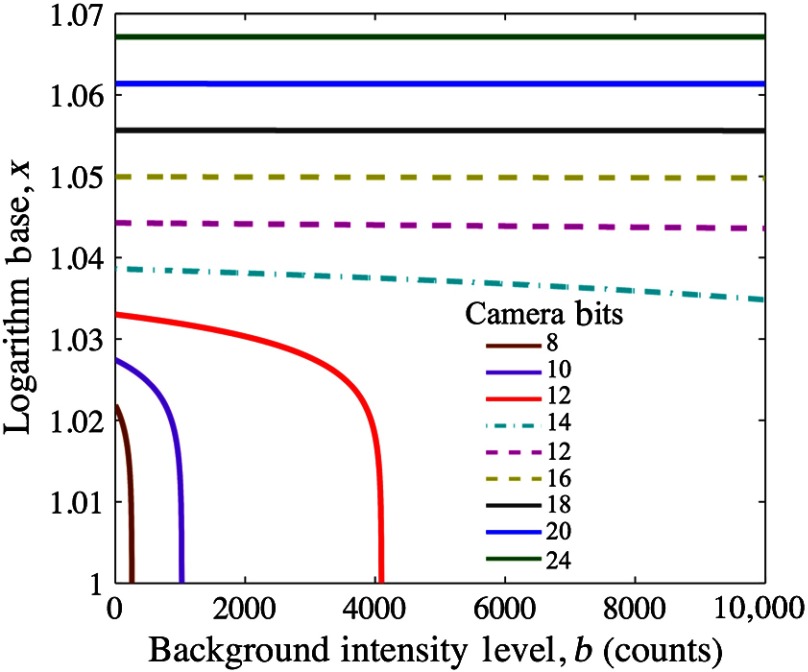
This function is plotted in Fig. 1, which shows that at high bit-depths, the impact of choice of log base though subtle is significant as bit-depth varies, whereas for a given camera system (constant bit-depth), the background intensity variation would matter little.
Fig. 1.
Logarithm base versus background intensity is plotted for various camera bit-depths to demonstrate that at high bit-depths, background signal intensity does not significantly affect the selection of log base .
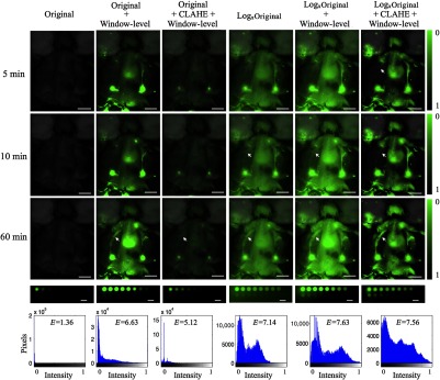
Figure 2 demonstrates an application of logarithmic compression to visualize lymphatic uptake of IRDye800CW conjugated to an antibody injected at the base of the tail of a mouse imaged with its skin folded back to reveal shallow lymphatic tracks and nodes. All animal experiments were carried out in accordance with the Institutional Animal Care and Use Committee at Dartmouth College under approved protocols. All images were acquired using the Pearl® Impulse system (LI-COR Biosciences, Lincoln, Nebraska) providing planar surface images of the dye. This has image digitization of 22 bits, thus providing an exceptionally high intensity dynamic range. The first column shows original fluorescence overlays in green over the white-light images for various time points after dye administration (rows).
Fig. 2.
Dye administered intradermally at the base of the tail travels via lymph vessels to the inguinal nodes (within 1 min after injection) and then toward the axillary nodes (5 to 10 min after injection).9 At the 60 min time point, dye can be seen in the left and right inguinal nodes and axillary nodes and also in the lymph vessels between these. Image entropy was used as a quantitative metric to compare the amount of visual information supplied by the original and each processed image. Figure 2 summarizes the observations.
The original images show very poor contrast as the ranges of intensities occupy only a fraction of the whole intensity range. This can be seen on the histogram on the bottom row of Fig. 2, for the 60 min time point, where image entropy was calculated to be 1.36. Manual window and level adjustments to the image enable stretching of the histogram to occupy a wider range of intensities and improve visualization of dye in lymph nodes/vessels. The one-step log-compressed images (compressed image intensity may need shifting/scaling to visible range) offer a promising alternative or add-on to manual window-level adjustment and provide a 4.25 times improvement in entropy over the original image. A second semiautomated approach combining window-level adjustment with contrast-limited adaptive histogram equalization (CLAHE)10 was applied to the original and log-compressed images for comparison. CLAHE applies histogram equalization to small regions of the image, so the resulting histogram of each is uniform and the final output image is a bilinear interpolation of the subregions. An overall entropy improvement of 4.56 times was achieved over the original image with this approach. The right lymph vessel (white arrows in Fig. 2) can be seen easily at the last time point in all processed images, but is visible only on the log-compressed images at 10 min due to the contrast-to-background improvement from 1.22 (original) to 3.58 (log compress+CLAHE+window level). Figure 2 includes a row of fluorescence images of well plates containing various concentrations of IRDye800CW fluorophore ( dilution series from to 0.49 nM) with 1% Intralipid and 0.08% India ink. The original linear intensity range of 0.002 to 2.31 A.U. is mapped to a range 0.33 to 1 A.U. of normalized fluorescence in the compressed image demonstrating a dramatic compression factor of 380.
Window and level adjustment is the simplest processing tool used to improve the visibility of dim features in images. However, manual adjustments, especially within a surgical setting dependent on real-time video sequences, are cumbersome. Besides this, window-leveling can often be biased by the user and important low-contrast features can easily be overlooked. On the other hand, optimized logarithmic compression is a tool that offers objective, bias-free contrast enhancement of images that span several orders of magnitude of intensities. The well-plate images at the bottom of Fig. 2 demonstrate that the mapping of greater than three orders of magnitude onto a visible range of 256 intensities can easily be achieved. Addition of background subtraction or window-leveling, in combination with the automated methods, removes issues of high background. Log-compression is relatively insensitive to intensity fluctuations, which would enable application of a single window-level adjustment setting at the start of an imaging sequence without the need for further manual adjustment. However, as surgical images, especially those from settings involving tumor resection, may be complicated by the presence of blood and other absorbers, future studies that apply log-compression to such image sequences may be necessary to test the practical aspects of such an approach.
In summary, fluorescence imaging has a long history in analysis and quantitative spectroscopy, with critical impact in flow cytometry today. The data produced here is a good example of the prevalent use of log-compression,7 attributable to the inherently high biological variance and cell labeling. Fluorescence imaging of molecular contrast should be the same, where variations in signal by orders of magnitude occur spatially from blood vessels to parenchyma on the microscopic level, and can be present on the macroscopic level between regions of high and low perfusion. On top of this biological variation, there are imaging system variations, which all contribute to a signal ranging over several orders of magnitude. Moreover, as camera systems gain a larger dynamic range, the compression of the display to improve information transfer to the user will become critical. Current 12-bit camera systems should likely employ a compression factor of 1.03 in their display, and as more advanced systems are produced at 14- or 16-bit, a compression factor of 1.04 may be more appropriate. These seemingly small number differences can have a large impact on the resulting image display.
Acknowledgments
This work has been funded by NIH grant R01CA109558. Author H.L. is supported by the Scholarship of Education Department of Fujian Province, China.
References
- 1.Preidl R. H., et al. , “Assessment of free microvascular flap perfusion by intraoperative fluorescence angiography in craniomaxillofacial surgery,” J. Craniomaxillofac. Surg. 43(5), 643–648 (2015). 10.1016/j.jcms.2015.03.013 [DOI] [PubMed] [Google Scholar]
- 2.Nguyen Q. T., Tsien R. Y., “Fluorescence-guided surgery with live molecular navigation—a new cutting edge,” Nat. Rev. Cancer 13(9), 653–662 (2013). 10.1038/nrc3566 [DOI] [PMC free article] [PubMed] [Google Scholar]
- 3.Dutt V., Greenleaf J. F., “Adaptive speckle reduction filter for log-compressed B-scan images,” IEEE Trans. Med. Imaging 15(6), 802–813 (1996). 10.1109/42.544498 [DOI] [PubMed] [Google Scholar]
- 4.Gao S., et al. , “Image overlay solution based on threshold detection for a compact near infrared fluorescence goggle system,” J. Biomed. Opt. 20(1), 016018 (2015). 10.1117/1.JBO.20.1.016018 [DOI] [PMC free article] [PubMed] [Google Scholar]
- 5.Roberts D. W., et al. , “Coregistered fluorescence-enhanced tumor resection of malignant glioma: relationships between delta-aminolevulinic acid-induced protoporphyrin IX fluorescence, magnetic resonance imaging enhancement, and neuropathological parameters. Clinical article,” J. Neurosurg. 114(3), 595–603 (2011). 10.3171/2010.2.JNS091322 [DOI] [PMC free article] [PubMed] [Google Scholar]
- 6.Drago F., et al. , “Adaptive logarithmic mapping for displaying high contrast scenes,” Comput. Graph. Forum 22(3), 419–426 (2003). 10.1111/1467-8659.00689 [DOI] [Google Scholar]
- 7.Herzenberg L. A., et al. , “Interpreting flow cytometry data: a guide for the perplexed,” Nat. Immunol. 7(7), 681–685 (2006). 10.1038/ni0706-681 [DOI] [PubMed] [Google Scholar]
- 8.Reinhard E., et al. , High Dynamic Range Imaging: Acquisition, Display, and Image-Based Lighting, Morgan Kaufmann, San Francisco, California: (2010). [Google Scholar]
- 9.Harrell M. I., Iritani B. M., Ruddell A., “Lymph node mapping in the mouse,” J. Immunol. Methods 332(1–2), 170–174 (2008). 10.1016/j.jim.2007.11.012 [DOI] [PMC free article] [PubMed] [Google Scholar]
- 10.Zuiderveld K., “Contrast limited adaptive histogram equalization,” in Graphics Gems IV, pp. 474–485, Academic Press Professional, Inc., San Diego, California: (1994). [Google Scholar]
Associated Data
This section collects any data citations, data availability statements, or supplementary materials included in this article.


