Abstract
A miniaturized, hermetically encased, wirelessly operated retinal prosthesis has been developed for preclinical studies in the Yucatan minipig, and includes several design improvements over our previously reported device. The prosthesis attaches conformally to the outside of the eye and electrically drives a microfabricated thin-film polyimide array of sputtered iridium oxide film electrodes. This array is implanted into the subretinal space using a customized ab externo surgical technique. The implanted device includes a hermetic titanium case containing a 15-channel stimulator chip and discrete circuit components. Feedthroughs in the case connect the stimulator chip to secondary power and data receiving coils on the eye and to the electrode array under the retina. Long-term in vitro pulse testing of the electrodes projected a lifetime consistent with typical devices in industry. The final assembly was tested in vitro to verify wireless operation of the system in physiological saline using a custom RF transmitter and primary coils. Stimulation pulse strength, duration, and frequency were programmed wirelessly from a Peripheral Component Interconnect eXtensions for Instrumentation (PXI) computer. Operation of the retinal implant has been verified in two pigs for up to five and a half months by detecting stimulus artifacts generated by the implanted device.
Index Terms: Biomedical electrodes, integrated circuit design, iridium oxide, neuromuscular stimulation, retinal implant, retinal prosthesis, telemetry
I. Introduction
Prostheses for the blind have been explored worldwide by many groups [1]–[15]. These devices are designed to restore some vision to patients who have become blind from degenerative retinal diseases like retinitis pigmentosa (RP) and age-related macular degeneration (AMD). Both of these conditions cause a gradual loss of photoreceptors, yet spare a substantial fraction of the retinal ganglion cells (RGCs). The axons of these RGCs form the optic nerve, which is a critical part of the neural pathway from the retina to the visual cortex. The prevalence of RP is approximately 1 in every 4000 live births, and there are approximately 1 700 000 affected individuals worldwide. AMD is the leading cause of blindness in the developed world, with roughly 2 million affected patients in the United States alone. This number is expected to increase 50% by the year 2020 as the population ages [16]. The best existing treatments slow or stabilize the progress of these diseases, but no treatment is available that can consistently restore functional improvement in vision. While there is clear evidence that significant reorganization of the retinal neurons occurs after the loss of input signals from the photoreceptors [17], our group and others have nevertheless shown that electrical stimulation of RGCs can produce visual percepts that vary with the strength and location of the stimulation (see, e.g., [18]). Some groups have even reported that severely blind patients can read with the assistance of a retinal prosthesis [1], [2], [19], [20].
To test the retinal prosthesis concept, our group performed six acute human retinal stimulation trials, surgically inserting thin-film electrode arrays near the epiretinal surface of the subjects’ eyes and driving current for a few hours from an external stimulator system [21]. Subjects reported visual percepts, including spots and lines [5], [6], but it became evident to our team that a chronically implantable device was required to allow patients to adapt to this artificial stimulation and fully explore the prospects for restoring useful vision.
Most visual prosthesis groups concentrate either on epiretinal stimulation of the front of the retina inside the eye [7], [8], or sub-retinal stimulation between the retina and the choroid [9], [10]. Less direct stimulation of the retina using supra-choroidal (between choroid and sclera) or trans-scleral (outside all or part of the sclera) approaches have also been used [11]–[13]. Our group began with an epiretinal approach, as in the human trials described earlier [5], [6], but changed to an ab externo, subretinal surgical approach, resulting in a less invasive surgery and improved biocompatibility, and leaving the bulk of the implant device outside the eye.
Our first-generation wirelessly powered implantable retinal stimulation device [3] was implanted in Yucatan minipigs in 2008. We now describe the design and functional results from an upgraded version of the implant with three major design changes: 1) protection of the implant circuits in a hermetic titanium enclosure; 2) more favorable magnetic coupling obtained by relocating the secondary coils to the front of the eye and increasing their size; and 3) easier surgical access for electrode array insertion. We also describe the results of long-term tests performed on our microfabricated thin-film electrode array, the only part of our device that enters the eye.
II. Retinal Implant Design
A. System Description
Our retinal prosthetic system includes both external and internal components. The external components include a PXI-based computer controller with a graphical user interface to select commands for the strength, duration, and spatial distribution (among other parameters) of electrical stimulation that is delivered to the retina. Commands from the external computer system are transmitted wirelessly to the implanted components of the prosthesis by near-field inductive coupling. Power is also wirelessly transmitted to the implant by the same method to create the implant’s power supplies.
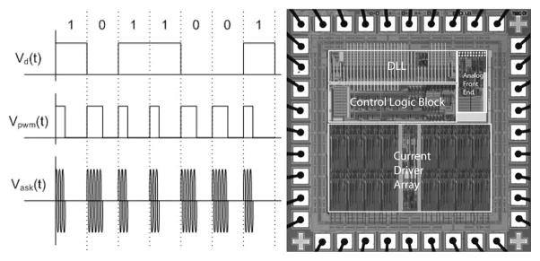
Stimulation data are transmitted to the implanted chip by a class A power amplifier with a 15.5-MHz carrier, amplitude shift keyed at a 100% modulation index. This frequency is sufficiently high to deliver the 16-bit commands and the 170-bit configuration package at a high enough frame rate while avoiding interference from the power carrier, but not so high as to have a large radiative component. Bits are encoded by pulsewidth modulation, with 30% duty cycle representing a digital 1 and 50% duty cycle representing a digital 0 (see Fig. 1). Power is transmitted by a class D power amplifier and a series resonant tank with a 125-KHz carrier, and is rectified in the implant by a dual half-wave rectifier, creating ±2.5-V anodal and cathodal supplies, clamped by a 5.1-V Zener diode. This frequency is high enough to allow rapid refreshing of the supply capacitors, but low enough to enable efficient power switching. The ±2.5-V supply was deemed sufficient to satisfy the requirements on this chip. Higher supplies would have required separate mid-rail cascode devices to protect the 5-V drive transistors, and this complexity was deemed unnecessary for this prototype [3], [22]. Telemetry of power and data has been tested in the laboratory at more than 30-mm separation between primary and secondary coils; a larger separation then is needed for our in vivo animal experiments or our future human work. At this large separation, there is increased power consumption in the primary coil. We operate the telemetry link at the minimum possible separation during in vivo trials.
Fig. 1.
(Left) Data are encoded in the carrier by amplitude shift keying (ASK), with pulsewidth modulation (PWM) encoding of bits. Duty cycle of 30% represents a 1, while 50% represents a 0. (Right) Custom integrated circuit for the retinal prosthesis. This 0.5-μm CMOS chip decodes incoming stimulation data with a delay locked loop and delivers desired stimulation currents to electrodes with 15 current sources.
Our custom integrated circuit [22] (see Fig. 1) is fabricated in 0.5-μm CMOS. This chip decodes the incoming data and delivers stimulating current to the appropriate electrodes based on the timing of transmitted commands. The chip is capable of delivering up to 930 μA per channel in 30-μA steps, using a linear current digital-to-analog converter (DAC). A linear current DAC was chosen over a logarithmic DAC because it is simpler to implement (does not require decoding logic), more standard in neural stimulators, and because we did not require the large dynamic range nor the reduced number of bits that make a logarithmic DAC attractive in some situations. Our current DAC circuit was designed to be an extremely flexible research tool and is capable of delivering more current than is needed for this animal work. Currents typically delivered to electrodes ranged from 30 to 120 μA.
The package containing the chip is attached to the outside of the eye, and its electrical stimulation current is delivered to the retinal nerve cells via a microfabricated thin-film array that contains sputtered iridium oxide film (SIROF) electrodes. The electrode array is surgically inserted into the subretinal space via an incision through the sclera and choroid.
B. Differences From First-Generation Device
Our first-generation device [3] (see Fig. 2) was assembled on a flexible polyimide substrate that wrapped part way around the eye inside the socket and was attached to the sclera of the eye. The device had three significant design drawbacks: 1) small receiver coils on the side of the eye had insufficient coupling to the primary coils, introducing power and data telemetry limitations; 2) the device had no hermetic packaging, but was coated with silicone, which survived studies up to ten months, but may not be viable for chronic trials of 5–10 years; and 3) the surgical procedure for electrode array insertion was very challenging, due to the need to operate through the coils.
Fig. 2.
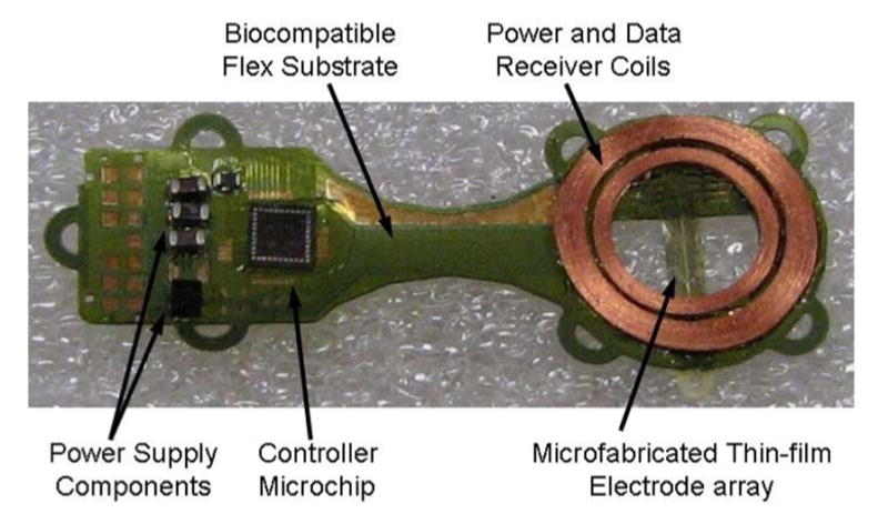
First-generation retinal prosthesis. The flexible implant wraps around the eye, with coils and electrode array in the superior-temporal quadrant and circuitry in the superior-nasal quadrant. The prosthesis receives power and data by inductive coupling, and the electrode array accesses the subretinal space via an incision through the sclera of the eye.
Our newer, second-generation device [4] (see Fig. 3) uses the same implant chip [22] and the same power and data telemetry scheme as the earlier device, but the new design surmounts the three limitations outlined earlier with, respectively: 1) larger coils on the front of the eye, surrounding the cornea under the conjunctiva and conforming to the curvature of the eye; 2) a hermetic, titanium case, which encloses the sensitive electronic circuitry and is attached to the sclera deep in the superior-nasal quadrant; and 3) a serpentine electrode array which extends from the case to the superior-temporal quadrant, away from the coils, allowing better surgical access to create the scleral flap and insert the electrode array into the subretinal space.
Fig. 3.
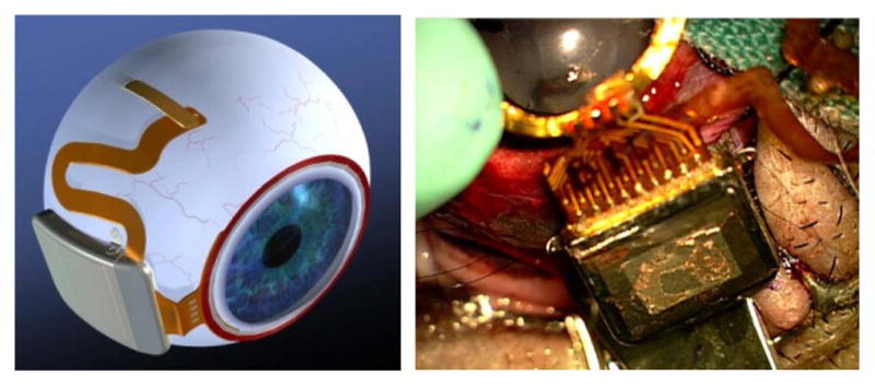
(Left) Artist’s drawing of the hermetic implant concept. The power and data receiver coils rest on the front of the eye, just beneath the conjunctiva. The electronics are encased in a hermetic titanium package, and the electrode array insertion is in its own quadrant, for ease of surgical access. (Right) Surgical implantation of an actual hermetic prosthesis onto a minipig eye.
C. Improved Implant Components
Relocation of the secondary power and data coils from the temporal side of the eye to the anterior aspect allowed for the use of larger coils, enabling much better inductive coupling and facilitating the incorporation of the primary coil into the frame of a pair of glasses for future human work. However, these coils rest just under the delicate conjunctiva and can wear through and become exposed over time, creating a risk of infection. To reduce this risk, the coils are carefully wound on a spherical mandrel so that they more closely match the curvature of the eye. The secondary coils include separate power and data windings and leads, but they are wound together for structural support. They are made of 40 AWG gold wire, with 28 turns for the power coil and two six-turn coils for a 12-turn center-tapped data receiver. The spherically molded coil has a mean radius of 9.5 mm and a thickness above the surface of the eye of less than 0.2 mm. The secondary coils are shown on a model eye in Fig. 4. The primary coils, also shown in Fig. 4, sit in front of the eye, coaxial with the secondary coils, and are made of separate power and data coils molded in a poly(dimethylsiloxane) (PDMS) body. The primary power coil has a mean radius of 19 mm, while the data coil has a mean radius of 12.5 mm.
Fig. 4.
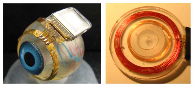
Hermetic retinal prosthesis and associated primary power and data coils. The implant on the left is a prototype of the device in Fig. 4, shown attached to a plastic model eye. The gold power and data secondary coils are formed on a sphere to match the eye’s curvature. The titanium case with welded lid, hermetic feedthrough, and epoxy header protects the internal circuitry. The electrode array is out of view over the top of the model eye. The primary coils on the right are potted in PDMS.
The implanted electronics are encased in the titanium enclosure, which measures 11 mm × 11 mm × 2 mm and is curved to conform more closely to the anatomical curvature of the eye. To create this enclosure, a small ceramic piece, 9.3 mm × 0.96 mm × 1.1 mm thick, was drilled with 19 staggered holes, each 0.13 mm in diameter. The two staggered rows have a pitch of 0.96 mm and spacing between rows of 0.3 mm for a diagonal spacing between holes of 0.57 mm. This pitch is considered to be near the limit for this type of drilled ceramic feedthrough due to concerns of ceramic cracking. However, our group is exploring other feedthrough technologies for future devices with higher electrode count, possibly in the hundreds. Through the drilled holes, platinum/iridium (90/10) wires 2.8 mm long were inserted, extending out of both sides of the ceramic feedthrough. Gold rings were fitted around the platinum/iridium wires and brazed to the ceramic for an airtight seal. The curved frame was machined from titanium, and the ceramic feedthrough with a gold strip around its edge was brazed into the case. The integrated circuit, which includes the telemetry receiver, digital controller, analog current sources, biasing, and startup circuitry, was flip-chip bonded to a circuit board, shown in Fig. 5. Additionally, Schottky rectifier diodes, two power supply capacitors, a discrete resistor and capacitor for power-up reset delay, a resonating capacitor for the power secondary coil, and a 5.1-V Zener diode for power supply regulation were soldered to the board. The top and bottom layer pads on the edge of the board were soldered to the inside pins of the feedthrough, and ground pads at the two corners opposite the feedthrough pins are soldered to pins attached to the corners of the case, allowing the titanium case to serve as a current return counter electrode for stimulation. The assemblies were baked for 24 h to drive off residual water, then titanium lids were laser welded onto the top and bottom of the case in a helium/argon ambient environment. Prior to welding, these lids had platinum sputtered onto portions of their surfaces to improve the charge-transfer capacity of the case as a counter electrode. Hermeticity of the case was evaluated using a Varian helium leak detection system, and leakage rates lower than 1 × 10− 9 std cc He/s were considered passing. The internal free volume of the case is approximately 90 mm2, and we estimate the projected lifetime of the package with the measured leak rate to be several years. Because of the small package volume, our leak rate was at or near the noise floor of the measurement system, and more sensitive measurements will be taken in the future. No desiccant was added to this device, but one may be incorporated into future versions. After case assembly and testing, the external feedthrough pins were soldered to the external flex circuit with gold–tin solder, and an epoxy header was molded over the external feedthrough connections, as shown in Fig. 4.
Fig. 5.
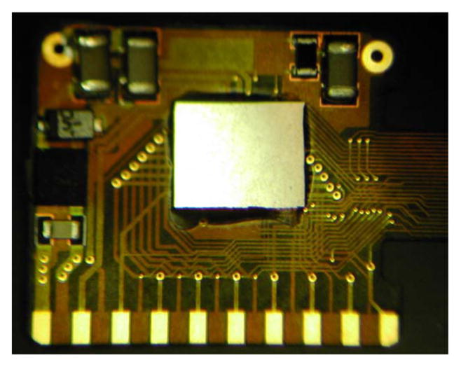
Retinal implant circuit board. The communication, control, and stimulation chip is attached alongside power supply components, and this board is inserted into the curved titanium package. The pads on the bottom are soldered to the hermetic feedthrough pins of the package.
The novel, serpentine design of our flexible, thin-film 16-μm-thick polyimide array of 400-μm diameter SIROF electrodes allows the surgeon to route it under the superior rectus or other extra-ocular muscles and insert the electrodes in the superior-temporal quadrant. The serpentine design also provides added length to give the surgeon some flexibility in the final insertion point of the electrodes. Numerous suture loops along the array allow the surgeon to affix the array to the sclera at many locations, thereby managing any small buckling that occurs from flexing the array. Since the titanium case is in the superior-nasal quadrant in our animal trials and given the low profile of our secondary coil, no part of the device interferes with the insertion of the array into the eye. The electrode array is inserted through that flap into a bleb created previously in the subretinal space (described later). Within one to two weeks, the retina slowly settles on top of the array and holds it in place. The placement of the electrode array in the subretinal space takes advantage of the eye’s natural forces that hold the retina against the choroid. The array is sutured to the sclera just outside the incision where it enters the eye, but no attachment is necessary in the subretinal space.
III. Testing Methods
A. Long-Term In Vitro Electrode Pulsing
Encasing the electronics in titanium allows this device to be implanted for a much longer time than the first-generation device, requiring additional testing of the microfabricated SIROF electrodes under chronic pulsing conditions. To assess the stability of these electrodes for chronic animal implantation, we subjected them to long-term in vitro pulsing. Arrays with 15 400-μm diameter electrodes were pulsed at 37 °C in an inorganic model of interstitial fluid (ISF) [23]. The multichannel stimulators for the in vitro pulsing experiments employ circuits generating an electrical current pulse protocol similar to that used in the implant for animal testing [24]. Eight electrodes on each array were pulsed at a charge density of 200 μC/cm2 (1-ms pulsewidth and 50-Hz repetition rate) using a 0.6-V Ag/AgCl interpulse bias [25]. Periodically, the model ISF was changed to ensure that there was no compositional drift during the long-term testing.
B. Implant In Vitro Testing
The full implant system was tested dry on the bench, as well as in vitro in a phosphate buffered saline solution. On the lab bench, dry testing was performed by connecting to the device through a test tail. Mock electrode loads, each consisting of a resistor in series with a parallel resistor–capacitor pair, were attached to the current source outputs. Balanced biphasic current pulses ranging from 30 to 240 μA were delivered with pulse durations of 1 ms. The load voltage was directly measured and recorded during wireless operation of the device.
During in vitro testing, the device was attached to a plastic eye model and submerged in a saline bath. Electrodes were driven with balanced biphasic pulses of current, 30–240 μA at 1-ms pulsewidth per phase (24–192 μC/cm2). (Similar stimulation parameters were used during in vivo stimulation trials, described below, performed in two Yucatan minipigs.) Electrode voltage was recorded via the test tail used in bench tests. The test tail was then cut off and the edge was covered in PDMS in preparation for implantation in the minipig. The device was then retested in the saline bath. Without the test tail, less-direct measurements of implant function were required. Needle electrodes were immersed in the saline, and the differential voltage between them was measured with a custom-built instrumentation amplifier. (To ensure that the device was working in the pig eye, the same type of measurement was made in vivo with a contact lens electrode on the eye surface and an ear reference electrode.)
C. Implant In Vitro Testing
The protocol for this research was approved by the animal care committees of the Massachusetts Institute of Technology, Cambridge, and the VA Boston Healthcare System, Boston. All animals were treated in accordance with the Association for Research in Vision and Ophthalmology resolution on the use of animals in research.
The hermetic devices were implanted in two minipigs, each weighing roughly 20 kg. Electroretinograms (ERGs) were taken preoperatively to assess the general health of each pig’s retina, and they were also taken at the beginning of subsequent examinations. The conjunctiva was cut open and dissected, a 6 mm wide × 2 mm long scleral flap was made in the superior temporal quadrant, a partial vitrectomy was performed, and a retinal bleb was raised with a needle from the front of the eye to separate the retina from the retinal pigment epithelium (RPE) and choroid. Next, the prosthesis package and secondary coil were attached to the sclera to secure them in place. The choroid was cauterized, and an incision was made through the choroid via the scleral flap. Then, the electrode array was inserted into the sub-retinal space where the retinal bleb had been created [26], [27]. The external portion of the array was sutured to the sclera, the corners of the scleral flap were sutured down, and the conjunctiva was sutured back over the implant. The device on the pig eye was shown in Fig. 3, and a sample histology slide taken after seven months of implantation of our thin-film polyimide electrode array in the subretinal space is shown in Fig. 6.
Fig. 6.
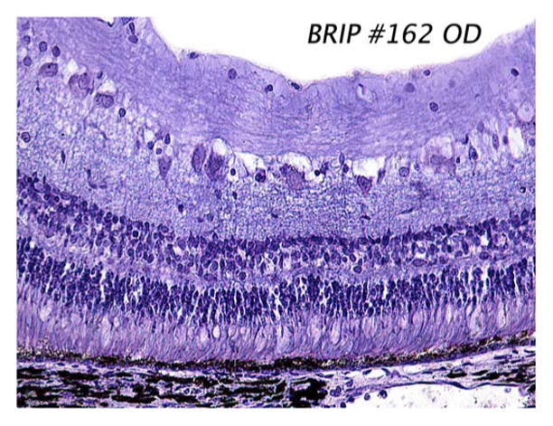
Sample histology slide taken seven months after implantation of our polyimide electrode array in the minipig subretinal space. The array, which was removed prior to sectioning, occupied the right-hand side of the slide. Note that the retina appears grossly normal, with no evident RPE cell proliferation. The stain used was 1% cresyl violet.
To establish function of the device, a contact lens electrode (ERG-JET) was placed on the pig’s eye, and two EKG-type electrodes (DWG-Z9526-69-AW Rev. B, by TraceRite Bio-Detek Inc., Pawtucket, RI) were placed on the ears. A differential measurement was made between the contact lens electrode and one of the ear electrodes, while the second ear electrode served as a reference voltage for the differential amplifier circuit used to record the signal. The primary telemetry coils were then placed near the front of the eye. Power and data were delivered to the device and adjusted until the recording electrode showed stimulus artifact from the chip’s pulsing current sources. Control measurements were taken by sending power and data to the implant and commanding zero current.
These measurements were entirely noninvasive and were meant to show continued function of the implant over time. We did not test any response from the minipig’s visual system. While it is common to test electrically evoked responses in the visual cortex of an animal, as we have acutely done in rabbits in the past [28], it is logistically difficult to record these signals in the pig in an acute experiment and quite difficult to do so chronically. The pig’s visual cortex is beneath a very thick layer of neck muscle and cranial bone, making access difficult even during a final, nonsurvival trial. Chronic recording from the visual cortex would require permanent fixture of electrodes drilled partway through the skull, with wires leading to a percutaneous connector. Our past experience suggests that pigs will knock any percutaneous head connector loose. Since we have previously stimulated human retina with similar parameters and recorded verbal descriptions of the visual percepts as well as drawings done by the subjects [5], [6], we determined that there was not enough to be learned from electrically evoked response recordings in minipigs to justify the risk to the pig or the effort to design a chronic cortical recording platform.
Followup examinations were conducted on the animals one week after implantation and approximately every three to four weeks thereafter. Because the measurements were noninvasive, the examinations were nonsterile procedures, though still took place in the surgical facility. The pig was anesthetized and ERG recordings were taken. The contact lens electrode, ear reference electrodes, and primary power and data coils were positioned by the surgeon. Power and data were delivered to the implant and the stimulus artifact was recorded as in the original surgery.
IV. Results and Discussion
A. Long-Term Electrode Pulsing
An example of the voltage transients from eight electrodes on one array and a representative current waveform are shown in Fig. 7. The voltage transients were quite similar for the eight electrodes with maximum cathodal electrode–electrolyte potential (Emc) of 0.25 ± 0.03 V versus AgAgCl, well positive of the −0.6-V water reduction potential on SIROF. Maximum total driving voltage was 0.85 ± 0.03 V. Cyclic voltammetry in the model ISF also showed a consistency in electrode response and good stability over long-term pulsing. In Fig. 8, the voltammograms of the eight pulsed electrodes are compared after 670 and 2900 h of pulsing. The cause of the observed changes in the CV response between 670 and 2900 h is unclear, although the observed changes would be consistent with a decrease in the density of the SIROF due to hydration. There was no protein in the model ISF, so the change is not due to protein denaturing. The periodic replacement of the model ISF precludes compositional drift over time. Fig. 9 shows an SEM image of an unpulsed control electrode and a pulsed test electrode after 2900 h.
Fig. 7.
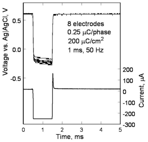
Voltage transients of eight SIROF electrodes on a polyimide array. The electrodes have been pulsed in an ISF model for 2900 h at 200 μC/cm2. A sample current waveform is also shown.
Fig. 8.
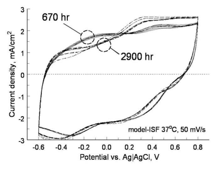
Cyclic voltammograms of eight SIROF electrodes in ISF model after 670 (solid) and 2900 h (dashed) of pulsing at 200 μC/cm2.
Fig. 9.
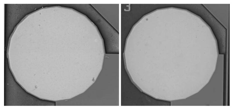
SEM images of SIROF electrodes after 2900 h in ISF. (Left) Unpulsed control electrode. (Right) Pulsed at 200 μC/cm2, 50 Hz.
B. Implant In Vitro and In Vivo Testing
A typical electrode in vitro test waveform is shown in Fig. 10. The RF power and data waveforms are visible in the figure. Also note the step-ramp shape of the electrode voltage waveform. Recall that bench tests of the prosthesis used a resistor in series with a parallel resistor–capacitor pair as a model electrode load. A current pulse through a series resistor and capacitor yields a characteristic step-ramp waveform. The additional resistor in parallel with the capacitor serves to curve the ramp slightly. The electrode voltage waveform in Fig. 10 shows not only the step from the resistive portions of the fluid and the electrode access resistance, but also the ramp from the charging of the electrode–tissue interface.
Fig. 10.
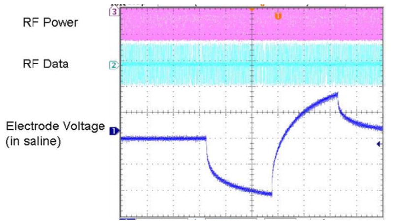
In vitro electrode test waveform for a wirelessly driven implant. The bottom waveform shows the electrode waveform in saline, measured via a test tail which is trimmed off before surgery.
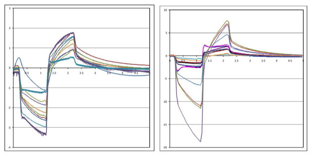
Recorded stimulus artifact waveforms from stimulation of the minipig eye are shown in Fig. 11. Because of the measurement setup, these waveforms show only the resistive portion of the voltage due to current flowing through fluid. The capacitive ramp in Fig. 10 shows charge buildup at the electrode–tissue interface, which is not measured by the contact lens electrode. The waveforms in Fig. 11 show a great deal of variation, largely due to inconsistencies in the placement of the contact lens electrode and the use of a distant reference electrode on the ear. With the reference electrode on the ear, well outside the field distribution from the electrode, the contact lens voltage is measured with respect to the pig’s body potential. The measurement electrode is placed on the cornea, which we believe may be near the center of the field distribution, where the potential is nearly equal to the pig’s body potential. Our amplifiers can show small differences in potential, but inconsistent placement, or even movement, of the contact lens electrode can result in drastic changes of the size (and even polarity) of the measured stimulus artifact waveforms. It is possible that some of the variation in Fig. 11 is from variation in impedance from one electrode to another, but we feel that contact lens placement is the dominant factor. Nonetheless, the goal of this measurement is to show the existence, not the amplitude, of stimulus artifacts, and when the artifact waveform is present, it is unmistakable. Furthermore, during control tests with the RF transmitters ON, but commanding zero-current pulses, we have seen no stimulus artifact [3].
Fig. 11.
Measured electrical stimulus artifact from two minipig eyes. Variation in waveform size is thought to be a result of variation in recording electrode position on the eye.
In both minipigs, the conjunctiva over the device wore through and caused exposure of the coils and case. This required explantation of the devices, one after three months and one after five and a half months. The details of the surgery and its complications will be discussed in a separate paper, but changes to the shape of the coil have shifted the leading edge of the coil to reduce tension on the conjunctiva. Also, the flex connection between the coils and the hermetic case was redesigned to shift the case farther back in the eye socket and improve its attachment to the eye. Development efforts on our device and surgical procedure are still underway.
V. Conclusion
A hermetically encased, wirelessly driven retinal prosthesis device has been developed. It has been tested both in vitro and in two Yucatan minipigs. Operation of the implant has been verified in the minipig eye for up to five and a half months. The device presented here is capable of being implanted for a much longer time than our previous PDMS-coated device, allowing for a target five-year survivability period for clinical trials. While our implant worked reliably during animal testing for several months, minor exposure problems at the conjunctiva forced an early end to both experiments. We have slightly redesigned the shape of the coils and the location of the case to ease the tension on the conjunctiva for future trials. These modifications will allow longer term animal implantation trials in the near future, with a view toward human clinical trials and the ultimate goal of a subretinal prosthesis capable of restoring useful vision to blind patients.
Acknowledgments
The authors acknowledge technical support from P. Troyk, T. Plante, O. Mendoza, J. Dumser, G. Swider, B. Yomtov, and J. Loewenstein, and administrative support from J. Balzer, S. Davco, K. Quinn, P. Davis, J. Palumbo, and G. Galanek. The authors acknowledge C. Pina, W. Hansford, and MOSIS for in-kind foundry services in support of their research, as well as the Cornell NanoScale Science and Technology Facility for fabrication support. Finally, the Department of Veterans Affairs and the Boston VA Healthcare System, the National Institutes of Health, the Department of Defense, and the Massachusetts Lions Foundation supported this research.
This work was supported in part by the Department of Veterans Affairs Center for Innovative Visual Rehabilitation, the NIH under Grant EY016674-01, the Department of Defense, NSF’s support to the Cornell NanoScale Science and Technology Facility, and the Massachusetts Lions Foundation. MOSIS provided in-kind foundry services.
Biographies

Shawn K. Kelly (M’03) received the S.B., M.Eng., and Ph.D. degrees in electrical engineering from the Massachusetts Institute of Technology (MIT), Cambridge, in 1996, 1998, and 2003, respectively.
He has researched cartilage and brain tissue resistivity at MIT and the University of Pittsburgh, and was a Test Engineer at M/A-Com. He joined the Boston Retinal Implant Project in 1996. Since 2003, he has been a Biomedical Engineer with the VA Center for Innovative Visual Rehabilitation, Boston, MA, and is a Visiting Scientist at MIT. His current interests include circuit design, power and data telemetry, and power management.
Dr. Kelly is a member of Sigma Xi and the Association for Research in Vision and Ophthalmology.

Douglas B. Shire (S’84–M’08) received the B.S. degree from Rensselaer Polytechnic Institute, Troy, NY, in 1984, and the Ph.D. degree from Cornell University, Ithaca, NY, in 1989.
He was with Hewlett Packard, Optoelectronics Division, and in 1994, he rejoined Cornell University as a Postdoctoral Associate, where he is currently a Visiting Scientist. He was an Adjunct Assistant Professor of electrical engineering at Syracuse University. In 1997, he joined Boston Retinal Implant Project, where he developed microfabrication processes for electrode arrays as a member of the VA Center for Innovative Visual Rehabilitation, Boston, MA. Since 2006, he has been an Engineering Manager.
Dr. Shire is a member of Tau Beta Pi, Eta Kappa Nu, and Association for Research in Vision and Ophthalmology.

Jinghua Chen received the M.D. degree from Peking University Health Science Center, Beijing, China, in 1995, and the Ph.D. degree from Peking University, Beijing, in 1999, where she completed her internship at the third Clinical Hospital and an ophthalmology residency at the second Clinical Hospital.
She joined the faculty at Peking University in 1999. In 2004, she joined Boston Retinal Implant Project, and is currently with the Massachusetts Eye and Ear Infirmary, Boston, MA. She performs acute and chronic in vivo research to test biocompatibility of the implant and has developed surgical methods for subretinal array and prosthesis implantation.
Dr. Chen is a member of Association for Research in Vision and Ophthalmology.

Patrick Doyle received the S.B. degree in electrical engineering from the Massachusetts Institute of Technology, Cambridge, in 1987, and the M.S. degree in electrical engineering from Northeastern University, Boston, MA, in 1995.
He was in industry for more than 20 years, developing digital communications systems for applications including intercept systems, underwater acoustic communications, cell phones, and law enforcement. In 2007, he joined Boston Retinal Implant Project as a Research Engineer with the VA Center for Innovative Visual Rehabilitation, Boston, MA.
Mr. Doyle is a member of the Association for Research in Vision and Ophthalmology.

Marcus D. Gingerich received the B.S. degree in electrical engineering from Michigan Technological University, Houghton, in 1992, and the M.S. degree in biomedical engineering, and the M.S. and Ph.D. degrees in electrical engineering from the University of Michigan, Ann Arbor, in 1994, 1996, and 2002, respectively.
In 2002, he joined Boston Retinal Implant Project, VA Center for Innovative Visual Rehabilitation, Boston MA, as a Biomedical Engineer. He is a Visiting Scientist at Cornell University, Ithaca, NY. He is involved in researching advanced microfabrication technologies for retinal prostheses.
Dr. Gingerich is a member of the Association for Research in Vision and Ophthalmology.

Stuart F. Cogan (M’95) received the B.Sc. degree in mechanical engineering, and the M.S. degree in materials science from Duke University, Durham, NC, in 1975 and 1977, respectively, and the Sc.D. degree in materials science from the Massachusetts Institute of Technology, Cambridge, in 1979.
He is currently the Director of Advanced Materials Research at EIC Laboratories, Inc., Norwood, MA. His research interests include materials for encapsulating implanted medical devices, and electrode materials for stimulation and recording.

William A. Drohan (M’07) received the B.E.E. degree from Manhattan College, New York, in 1958, and the M.E.E. degree from Rensselaer Polytechnic Institute, Troy, NY, in 1960.
Since 2005, he has been a Research Engineer with the VA Center for Innovative Visual Rehabilitation, Boston, MA, and also a Research Affiliate at the Massachusetts Institute of Technology, Cambridge. His current research interests include modeling of neural systems.
Mr. Drohan is a member of Eta Kappa Nu and Sigma Xi.

Sonny Behan is currently a Mechanical Engineer and the President of Sonny Behan Consulting, Atlanta, GA. He serves as a Design Consultant for the Boston Retinal Implant Project. He has more than 25 years of experience in the design of implantable medical products. He holds five patents.

Luke Theogarajan received the Ph.D. degree from the Massachusetts Institute of Technology, Cambridge, in 2007.
He is currently an Assistant Professor of electrical and computer engineering at the University of California, Santa Barbara. His research interests include combining the processing power of electronics with the versatility of synthetic chemistry to develop neural prosthetic devices. He holds four patents.

John L. Wyatt (S’75–M’78–SM’95) received the S.B. degree from the Massachusetts Institute of Technology (MIT), Cambridge, in 1968, the M.S. degree from Princeton University, Princeton, NJ, in 1970, and the Ph.D. degree from the University of California, Berkeley, in 1979, all in electrical engineering.
After postdoctoral research in the Department of Physiology, Medical College, Richmond, VA, he joined the Department of Electrical Engineering and Computer Science at MIT, where he is currently a Professor. He headed a project on analog integrated circuits for machine vision from 1988 to 1995. He is also a Co-Director of Boston Retinal Implant Project.

Joseph F. Rizzo, III, received the B.S. degree from Louisiana State University, Baton Rouge, in 1974, and the M.D. degree from Louisiana State University Medical School, New Orleans, in 1978. He completed internship in adult medicine at Los Angeles Medical Center, University of California, and residencies in neurology at Tufts University New England Medical Center, Boston, MA, and in ophthalmology at Boston University, Boston.
He performed a clinical fellowship in neuro-ophthalmology in the Department of Ophthalmology, Massachusetts Eye and Ear Infirmary Harvard Medical School, Boston, MA, where he joined the faculty. He initiated Boston Retinal Implant Project in 1988, and is its Co-Director. He is the Director of the VA Center for Innovative Visual Rehabilitation, Boston.
Prof. Rizzo received the Dean’s Award from Louisiana State University Medical School, and a Physician Training Award from the NIH.
Footnotes
Color versions of one or more of the figures in this paper are available online at http://ieeexplore.ieee.org.
Contributor Information
Shawn K. Kelly, Email: skkelly@alum.mit.edu, Center for Innovative Visual Rehabilitation, VA Boston Healthcare System, Boston, MA 02130 USA, and also with the Research Laboratory of Electronics, Massachusetts Institute of Technology, Cambridge, MA 02139 USA.
Douglas B. Shire, Email: dbs6@cornell.edu, Center for Innovative Visual Rehabilitation, VA Boston Healthcare System, Boston, MA 02130 USA, and also with Cornell University, Ithaca, NY 14853 USA.
Jinghua Chen, Email: jinghua_chen@meei.harvard.edu, Department of Ophthalmology, Harvard Medical School and the Massachusetts Eye and Ear Infirmary, Boston, MA 02114 USA.
Patrick Doyle, Email: billd@mit.edu, Center for Innovative Visual Rehabilitation, VA Boston Healthcare System, Boston, MA 02130 USA, and also with the Research Laboratory of Electronics, Massachusetts Institute of Technology, Cambridge, MA 02139 USA.
Marcus D. Gingerich, Email: mdg37@cornell.edu, Center for Innovative Visual Rehabilitation, VA Boston Healthcare System, Boston, MA 02130 USA, and also with Cornell University, Ithaca, NY 14853 USA
Stuart F. Cogan, Email: scogan@eiclabs.com, EIC Laboratories, Inc., Norwood, MA 02062 USA.
William A. Drohan, Email: wpd@mit.edu, Center for Innovative Visual Rehabilitation, VA Boston Healthcare System, Boston, MA 02130 USA, and also with the Research Laboratory of Electronics, Massachusetts Institute of Technology, Cambridge, MA 02139 USA.
Sonny Behan, Email: sbehan@bellsouth.net, Sonny Behan Consulting, Atlanta, GA 30096 USA.
Luke Theogarajan, Email: ltheogar@ece.ucsb.edu, University of California, Santa Barbara, CA 92106 USA.
John L. Wyatt, Email: jlw@mit.edu, Research Laboratory of Electronics, Massachusetts Institute of Technology, Cambridge, MA 02139 USA.
Joseph F. Rizzo, III, Email: joseph_rizzo@meei.harvard.edu, Center for Innovative Visual Rehabilitation, VA Boston Healthcare System, Boston, MA 02130 USA, and also with the Department of Ophthalmology, Harvard Medical School, and the Massachusetts Eye and Ear Infirmary, Boston, MA 02114 USA.
References
- 1.Brindley GS, Lewin WS. The sensations produced by electrical stimulation of the visual cortex. J Physiol. 1968;196:479–493. doi: 10.1113/jphysiol.1968.sp008519. [DOI] [PMC free article] [PubMed] [Google Scholar]
- 2.Dobelle WH, Mladejovsky MG, Evans JR, Roberts TS, Girvin JP. ‘Braille’ reading by a blind volunteer by visual cortex stimulation. Nature. 1976;259:111–112. doi: 10.1038/259111a0. [DOI] [PubMed] [Google Scholar]
- 3.Shire DB, Kelly SK, Chen J, Doyle P, Gingerich MD, Cogan SF, Drohan W, Mendoza O, Theogarajan L, Wyatt JL, Rizzo JF. Development and implantation of a minimally-invasive, wireless sub-retinal neurostimulator. IEEE Trans Biomed Eng. 2009 Oct;56(10):2502–2511. doi: 10.1109/TBME.2009.2021401. [DOI] [PMC free article] [PubMed] [Google Scholar]
- 4.Kelly SK, Shire DB, Chen J, Doyle P, Gingerich MD, Drohan WA, Theogarajan LS, Cogan SF, Wyatt JL, Rizzo JF., III Realization of a 15-channel, hermetically-encased wireless subretinal prosthesis for the blind. Proc IEEE Eng Med Biol Conf. 2009 Sep;:200–203. doi: 10.1109/IEMBS.2009.5333619. [DOI] [PMC free article] [PubMed] [Google Scholar]
- 5.Rizzo JF, III, Wyatt J, Loewenstein J, Kelly S, Shire D. Perceptual efficacy of electrical stimulation of human retina with a microelectrode array during short-term surgical trials. Invest Ophthalmol Vis Sci. 2003;44:5362–5369. doi: 10.1167/iovs.02-0817. [DOI] [PubMed] [Google Scholar]
- 6.Rizzo JF, III, Wyatt J, Loewenstein J, Kelly S, Shire D. Methods and perceptual thresholds for short-term electrical stimulation of human retina with microelectrode arrays. Invest Ophthalmol Vis Sci. 2003;44:5355–5361. doi: 10.1167/iovs.02-0819. [DOI] [PubMed] [Google Scholar]
- 7.Yanai D, Weiland JD, Mahadevappa M, Greenberg RJ, Fine I, Humayun MS. Visual performance using a retinal prosthesis in three subjects with retinitis pigmentosa. Amer J Ophthalmol. 2007;143:820–827. doi: 10.1016/j.ajo.2007.01.027. [DOI] [PubMed] [Google Scholar]
- 8.Gerding H, Benner FP, Taneri S. Experimental implantation of epiretinal retina implants (EPI-RET) with an IOL-type receiver unit. J Neural Eng. 2007;4:S38–S49. doi: 10.1088/1741-2560/4/1/S06. [DOI] [PubMed] [Google Scholar]
- 9.DeMarco PJ, Jr, Yarbrough GL, Yee CW, Mclean GY, Sagdullaev BT, Ball SL, McCall MA. Stimulation via a subretinally placed prosthetic elicits central activity and induces a trophic effect on visual responses. Invest Ophthalmol Vis Sci. 2007;48:916–926. doi: 10.1167/iovs.06-0811. [DOI] [PubMed] [Google Scholar]
- 10.Schanze T, Sachs HG, Wiesenack C, Brunner U, Sailer H. Implantation and testing of subretinal film electrodes in domestic pigs. Exp Eye Res. 2006;82:332–340. doi: 10.1016/j.exer.2005.07.007. [DOI] [PubMed] [Google Scholar]
- 11.Zhou JA, Woo SJ, Park SI, Kim ET, Seo JM, Chung H, Kim SJ. A suprachoroidal electrical retinal stimulator design for long-term animal experiments and in-vivo assessment of its feasibility and biocompatibility in rabbits. J Biomed Biotech. 2008;2008:547428-1–547428-10. doi: 10.1155/2008/547428. [DOI] [PMC free article] [PubMed] [Google Scholar]
- 12.Wong YT, Dommel N, Preston P, Hallum LE, Lehmann T, Lovell NH, Suaning GJ. Retinal neurostimulator for a multi-focal vision prosthesis. IEEE Trans Neural Syst Rehab Eng. 2007 Sep;15(3):425–434. doi: 10.1109/TNSRE.2007.903958. [DOI] [PubMed] [Google Scholar]
- 13.Terasawa Y, Tashiro H, Uehara A, Saitoh T, Ozawa M, Tokuda T, Ohta J. The development of a multichannel electrode array for retinal prostheses. J Artif Organs. 2006;9:263–266. doi: 10.1007/s10047-006-0352-1. [DOI] [PubMed] [Google Scholar]
- 14.Hornig R, Zehnder T, Velikay-Parel M, Laube T, Feucht M, Richard G. The IMI Retinal Implant System. In: Humayun MS, Weiland JD, Chader G, Greenbaum E, editors. Artificial Sight: Basic Research, Biomedical Engineering, and Clinical Advances. New York: Springer; 2007. pp. 111–128. [Google Scholar]
- 15.Zrenner E. Restoring neuroretinal function: New potentials. Doc Ophthalmol. 2007;115:56–59. [Google Scholar]
- 16.Friedman D, O’Colmain B, Munoz B, Tomany SC, McCarty C, de Jong PT, Nemesure B, Mitchell P, Kempen J. Prevalence of age-related macular degeneration in the united states. Arch Ophthalmol. 2004;122:564–572. doi: 10.1001/archopht.122.4.564. [DOI] [PubMed] [Google Scholar]
- 17.Marc RE, Jones BW, Anderson JR, Kinard K, Marshak DW, Wilson JH, Wensel TG, Lucas RJ. Neural reprogramming in retinal degenerations. Invest Ophthalmol Vis Sci. 2007;48:3364–3371. doi: 10.1167/iovs.07-0032. [DOI] [PMC free article] [PubMed] [Google Scholar]
- 18.Jensen RJ, Rizzo JF., III Responses of ganglion cells to repetitive electrical stimulation of the retina. J Neural Eng. 2007;4:S1–S6. doi: 10.1088/1741-2560/4/1/S01. [DOI] [PubMed] [Google Scholar]
- 19.Humayun MS. Preliminary results from argus II feasibility study: A 60 electrode epiretinal prosthesis. Invest Ophthalmol Vis Sci. 2009;50:4744. [Google Scholar]
- 20.Sachs HG, Bartz-Schmidt U, Gekeler F, Besch D, Brunner U, Wilhelm B, Wrobel W, Wilke R, Gabel VP, Zrenner E. The transchoroidal implantation of subretinal active micro-photodiode arrays in blind patients: Long term surgical results in the first 11 implanted patients demonstrating the potential and safety of this new complex surgical procedure that allows restoration of useful visual percepts. Invest Ophthalmol Vis Sci. 2009;50:4742. [Google Scholar]
- 21.Kelly SK. M Eng thesis. Massachusetts Inst. Technol; Cambridge: 1998. A system for electrical retinal stimulation for human trials. [Google Scholar]
- 22.Theogarajan LS. A low-power fully implantable 15-channel retinal stimulator chip. IEEE J Solid-State Circuits. 2008 Oct;43(10):2322–2337. [Google Scholar]
- 23.Cogan SF, Troyk PR, Ehrlich J, Gasbarro CM, Plante TD. The influence of electrolyte composition on the in vitro charge-injection limits of activated iridium oxide (AIROF) stimulation electrodes. J Neural Eng. 2007;4:79–86. doi: 10.1088/1741-2560/4/2/008. [DOI] [PubMed] [Google Scholar]
- 24.Srivastava NR, Troyk PR, Cogan SF. A laboratory testing and driving system for AIROF microelectrodes. Proc IEEE Eng Med Biol Conf. 2004 Sep;:4271–4274. doi: 10.1109/IEMBS.2004.1404190. [DOI] [PubMed] [Google Scholar]
- 25.Cogan SF, Troyk PR, Ehrlich J, Plante TD. In vitro comparison of the charge-injection limits of activated iridium oxide (AIROF) and platinum-iridium microelectrodes. IEEE Trans Biomed Eng. 2005 Sep;52(9):1612–1614. doi: 10.1109/TBME.2005.851503. [DOI] [PubMed] [Google Scholar]
- 26.Chen J, Doyle P, Cai C, Dumser J, Akhmechet R, Gingerich MD, Kelly SK, Shire DB, Rizzo JF. Surgical implantation of 1.5 generation retinal implant in minipig eyes. Invest Ophthalmol Vis Sci. 2010;51:3052. [Google Scholar]
- 27.Chen J, Shah HA, Herbert C, Loewenstein J, Rizzo JF., III Extraction of a chronically implanted, microfabricated, sub-retinal electrode array. Ophthalmic Res. 2009;42:128–137. doi: 10.1159/000227278. [DOI] [PubMed] [Google Scholar]
- 28.Shah HA, Montezuma SR, Rizzo JF., III In vivo electrical stimulation of rabbit retina: Effect of stimulus duration and electric field orientation. Exp Eye Res. 2006;83(2):247–254. doi: 10.1016/j.exer.2005.11.023. [DOI] [PubMed] [Google Scholar]


