Significance
Active liquid crystals are aqueous in vitro suspensions of cytoskeletal proteins that self-assemble into elongated fibers and develop sustained flows at the continuous expense of ATP. When they condense on soft interfaces, the aligned fibers organize into nonequilibrium analogs of passive liquid crystals. However, proteins do not respond to external electromagnetic fields, unlike liquid crystals, which are readily reconfigured inside devices. We demonstrate a reversible and biocompatible experimental protocol to align an active liquid crystal with a uniform magnetic field, allowing the transition between turbulent and laminar flow regimes. The active liquid crystal senses the interfacial viscous anisotropy of a lamellar hydrophobic liquid crystal, not unlike the adaptation of cells to the mechanical features of their environment.
Keywords: active matter, liquid crystals, cytoskeleton, kinesin
Abstract
Living cells sense the mechanical features of their environment and adapt to it by actively remodeling their peripheral network of filamentary proteins, known as cortical cytoskeleton. By mimicking this principle, we demonstrate an effective control strategy for a microtubule-based active nematic in contact with a hydrophobic thermotropic liquid crystal. By using well-established protocols for the orientation of liquid crystals with a uniform magnetic field, and through the mediation of anisotropic shear stresses, the active nematic reversibly self-assembles with aligned flows and textures that feature orientational order at the millimeter scale. The turbulent flow, characteristic of active nematics, is in this way regularized into a laminar flow with periodic velocity oscillations. Once patterned, the microtubule assembly reveals its intrinsic length and time scales, which we correlate with the activity of motor proteins, as predicted by existing theories of active nematics. The demonstrated commanding strategy should be compatible with other viable active biomaterials at interfaces, and we envision its use to probe the mechanics of the intracellular matrix.
Liquid crystals are viscous fluids that self-assemble into equilibrium molecular arrangements featuring anisotropic physical properties that can be easily tailored by suitable boundary conditions, and reversibly rearranged by using modest electric or magnetic fields (1). These soft matter mesophases are not exclusive of artificial materials, as they are ubiquitous in lipid solutions (2) and concentrated DNA fragments (3), and have been recently obtained by in vitro cytoskeletal reconstitutions based on aqueous suspensions of filamentous proteins cross-linked by compatible molecular motors (4–6). The latter type of materials is referred to as active liquid crystals because, unlike their passive counterparts, they exhibit out-of-equilibrium behavior with supramolecular orientational order that is dynamically self-assembled at the continuous expense of hydrolysable adenosine triphosphate (ATP). Experiments with active soft matter (7–17) reveal self-organizing features that are not present in passive materials. Despite the vast richness of behavior endowed by activity, traditional liquid crystals have a dramatic advantage: their orientation can be easily controlled to switch among different predesigned configurations, which is crucial for the operation of devices, and for fundamental research in partially ordered materials. Contrarily, experiments on active nematics have relied on establishing their composition, confinement geometry, or activity as design parameters, but they lack true control capabilities of the resulting dynamic self-assembly. This limits their potential to serve as in vitro model systems of the intracellular matrix or for the development of new functional biomaterials. Here, by interfacing an active nematic film with a hydrophobic oil that features smectic (lamellar) liquid-crystalline order (18), we reversibly align the originally turbulent flow of the active fluid into well-designed flow directions by means of a magnetic field.
Results and Discussion
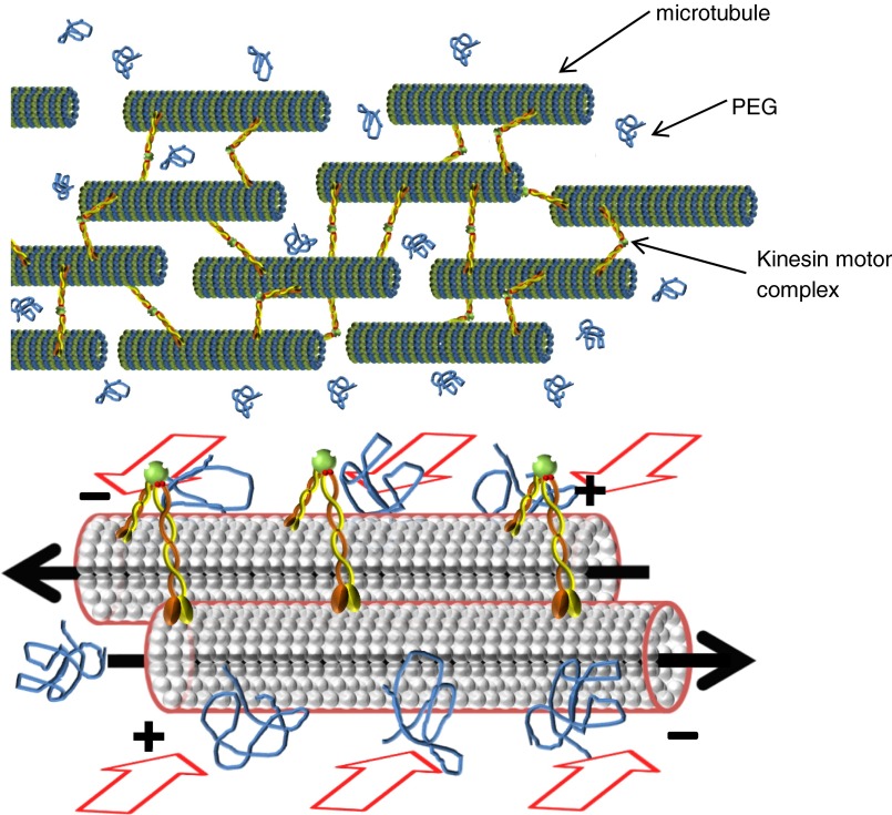
The chosen active material is an aqueous gel based on the self-assembly of micrometer-sized stabilized microtubules (MTs) (4, 19). The latter are cross-linked and locally sheared by clusters of ATP-fueled kinesin motors, which are directed toward the plus ends of the MTs. Thus, interfilament sliding occurs in bundles containing MTs of opposite polarity (Fig. S1). This mixture arranges into an extensile active gel (20–22), continuously rebuilt following bundle reconstitution, and permanently permeated by streaming flows. An active nematic is obtained by concentrating this bulk material, using a depletion force, toward a biocompatible soft and flat interface, usually a surfactant-decorated isotropic oil. Assembled filaments continuously fold and adopt textures typical of a 2D nematic phase (4). This active film appears punctuated by a steady number of continuously renovated MT-void regions that configure semiinteger defect areas (Fig. 1A). In our case, the active nematic is formed at the interface between the aqueous protein suspension and a volume of the hydrophobic oil octyl-cyanobiphenyl (8CB), which features two liquid crystal phases at temperatures compatible with protein activity. The 8CB/water interface is stabilized with a polyethylene glycol (PEG)-based triblock copolymer surfactant, which also promotes the alignment of the thermotropic liquid crystal molecules parallel to the interface. Real-time observation is performed using fluorescence, polarization, and confocal microscopies (Materials and Methods).
Fig. S1.
Sketch of the water-based active gel and its components. Bundles of MTs are formed via depletion interaction, which is triggered by the presence of polyethylene glycol (PEG) in the suspension, as illustrated by the red arrows. Within bundles, MTs are cross-linked by ATP-activated kinesin motor clusters, which induce interfilament sliding when adjacent MTs are oppositely aligned. The local forces exerted by the protein complexes result in synchronized collective motility.
Fig. 1.
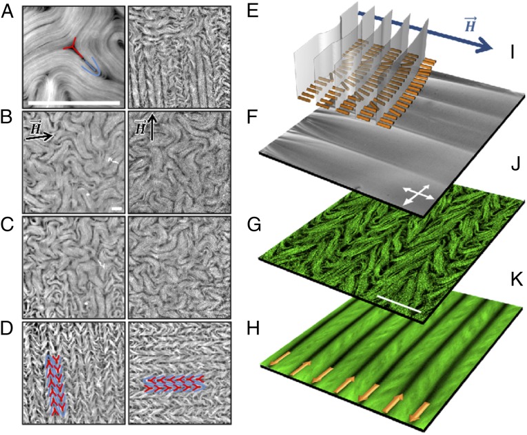
Alignment of the active nematic with a magnetic field. (A) Fluorescence micrograph of the active nematic with a pair of complementary +1/2 (blue) and −1/2 (red) defects highlighted. (B–H) Fluorescence micrographs with different configurations of the active nematic in the presence of a 4-kG uniform magnetic field. (B) The active fluid is initially in contact with nematic 8CB, which is transited, below T0 = 33.4 °C, into the lamellar smectic-A phase (C) under a horizontal magnetic field. (D) The active nematic aligns perpendicularly to the field. By temperature cycling above (E and F) and below (G and H) T0 under a vertical magnetic field, the active nematic is now realigned in the orthogonal direction (H). Pairs of aligned defects are highlighted in D and H. (I) Polarizing optical micrograph, and configuration of the underlying molecular planes in the SmA phase of the passive liquid crystal. (J) Fluorescence confocal micrograph revealing the correlation between the aligned active nematic and the anisotropic SmA phase. (K) Time average of the dynamic pattern. The arrows depict the antiparallel flow directions along the lanes of defect cores. (Scale bars: 100 μm.)
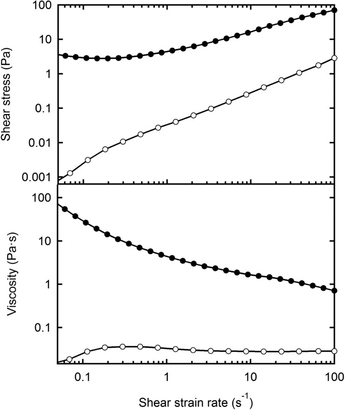
When the thermotropic liquid crystal across the flat interface features the nematic phase (T > 33.4 °C), the active nematic displays the usual self-sustained turbulent flow characterized by the random proliferation of ±1/2 defects that unbind in pairs during spontaneous filament folding (23–26) (Fig. 1A). The dynamic viscosity of nematic 8CB is 30 mPa⋅s (Fig. S2), which is significantly higher than that of isotropic oils used earlier in the literature (4). This fact results in a lower average speed of the active flow, and a higher defect density for the same concentration of ATP, a clear evidence of the hydrodynamic influence that the passive fluid exerts on the active one. When our experiment is performed in the presence of a uniform in-plane magnetic field of 4 kG, created by a permanent magnet array (Materials and Methods), 8CB molecules align with the field due to the positive diamagnetic anisotropy of this material. Nevertheless, we cannot detect any resulting alteration in the structure or in the dynamics of the active nematic underneath (Fig. 1B).
Fig. S2.
Rheology measurements for 8CB. Average steady-state shear stress and viscosity for 8CB measured in the SmA phase (25 °C, ●) and in the nematic phase (35 °C, ○). Measurements have been performed using a Thermo Haake RheoStress 1 rheometer, in constant stress mode, using cone-plate geometry with a 1°, 60-mm-diameter titanium cone.
To increase the interfacial shear stress anisotropy, we quench the temperature below 33.4 °C, which results in 8CB transiting into the lamellar smectic-A (SmA) phase, which is characterized by molecules organized perpendicular to the lamellar planes. The active nematic rapidly rearranges due to the new boundary conditions (Fig. 1 C and D and Movie S1), so that the chaotic filament orientation is now regularized into parallel stripes of uniform width aligned perpendicularly to the magnetic field. Fluorescence microscopy indicates that the bright stripes consist of densely packed MT bundles, whereas intercalated dark lanes incorporate the cores of proliferating ±1/2 defects. Notice that strings of alternated +1/2 and −1/2 defects align and move in antiparallel directions in adjacent lanes (Fig. 1D). During the slow temperature ramp, there is a transient state where regions with 8CB in the nematic and in the SmA phase coexist, resulting in growing areas where the active nematic is aligned, together with vanishing regions where it is still disordered (Fig. 1C). The active nematic adapts to the new interfacial state almost instantaneously for all explored activities (Movie S2). The alignment process is reversible and versatile. By cycling the temperature above and below 33.4 °C (Fig. 1 E–G), the active nematic returns to the disordered state when freed from the interfacial constraints (Fig. 1F), and a new direction of alignment can be arbitrarily chosen by rotating the magnetic field (Fig. 1H and Movie S3).
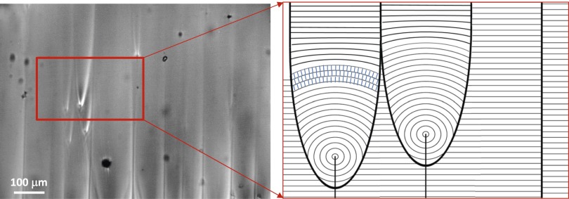
This alignment effect can be understood by taking into account the structure of the contacting SmA phase. As mentioned above, 8CB molecules organize in planes perpendicular to their orientation, which is parallel to the magnetic field. Consequently, the SmA planes are perpendicular both to the 8CB/water interface and to the field (Fig. 1I). Polarizing optical microscopy confirms the formation of this aligned SmA layer (Fig. 1I), which includes dislocations in the aligned planes that propagate into the bulk forming the so-called parabolic focal conic domains (Fig. S3). It is well known in the literature (18) that this “bookshelf” geometry of the SmA phase results in a liquid that flows easily when sheared along the planes, but responds as a solid to stresses exerted in the orthogonal direction. As a consequence of this configuration, the active nematic encounters an interfacial viscosity that is much higher for flow along the magnetic field than perpendicular to it, resulting in the observed alignment (Fig. 1 J and K).
Fig. S3.
Parabolic focal conic domains in the aligned SmA phase. Polarizing optical micrograph of the 8CB SmA phase in contact with the aqueous active material. When formed under a uniform magnetic field (aligned along the vertical direction in this image), the SmA planes are perpendicular to the interface, to the molecules, and to the applied field. During the nucleation of the SmA phase, topological defects in the form of parabolic-shaped domains, bound by dislocations of the SmA planes, are observed.
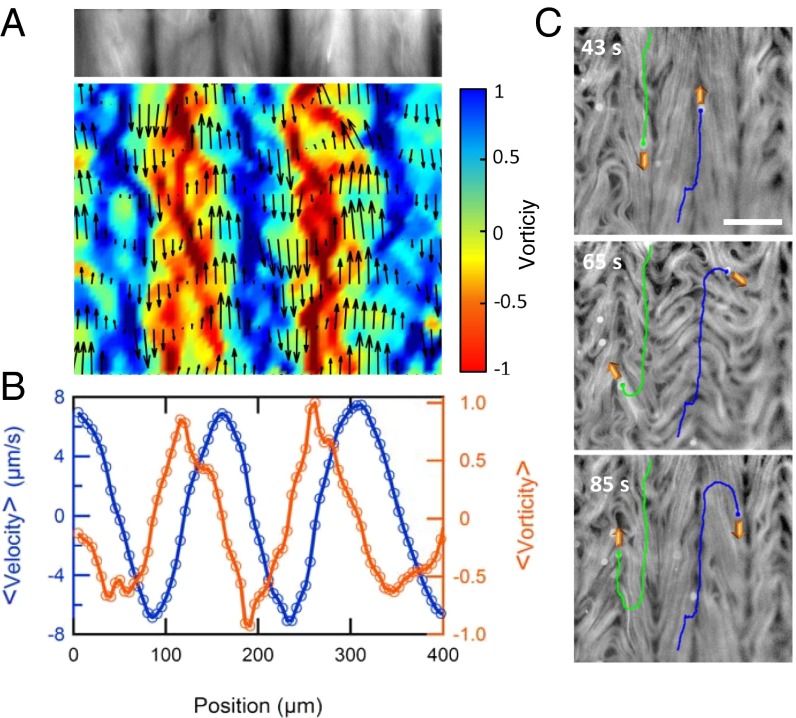
The reported phenomenon is different from the alignment of a passive liquid crystal under shear flow. On the one hand, here the stress originates in the active fluid, and the interface provides only with a reconfigurable anisotropic template for alignment. On the other hand, there is no global net flow of the active nematic. As explained above, the aligned active filaments give rise to stripes intercalated by lanes with alternate antiparallel flow patterns (Fig. 1K). We have performed a velocimetry analysis on the moving active filaments (Fig. 2 A and B) and have observed that the average speed is highest along the lanes where defect cores organize, and that it vanishes on the stripes where MTs pack. Velocity gradients follow the complementary pattern, being the highest at the points of flow stagnation. By seeding the active nematic with tracer microparticles, we put into evidence that the aligned lanes are able to actively transport biocompatible cargo (Fig. 2C and Movie S4).
Fig. 2.
Active flow along self-organized lanes. (A) Local velocity (vector plot) and local normalized vorticity (∂vy/∂x − ∂vx/∂y, color density plot) in a vertically aligned active nematic film. A transversal cut of the time-averaged fluorescence micrograph is shown above the plot. (B) Downstream average of velocity and vorticity across the horizontal position. (C) Fluorescence micrograph with the path of colloidal tracers being advected in neighboring (i.e., antiparallel) flow lanes. Local instability of the aligned pattern may lead to lane jumps (Middle) and thus to velocity inversion (Bottom) of the transported particles. (Scale bar: 100 μm.)
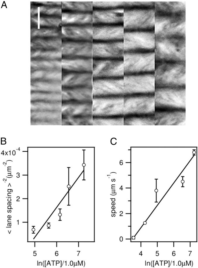
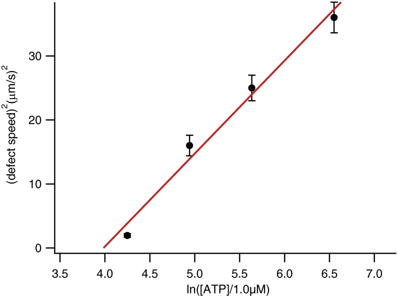
Recent models to describe the dynamic self-assembly of freely suspended active nematic films propose that steady-state patterns will be characterized by an intrinsic length scale, l, which is the result of a balance between the forces required to deform the elongated MT bundles and the active stress provided by the molecular motors (27). This leads to a scaling relation l−2 ∼ α, where α is the activity parameter, linearly related to the chemical potential for ATP hydrolysis, α ∼ ln[ATP]. We have analyzed the active nematic patterns aligned under a magnetic field for different activities, characterizing the spatial periodicity in terms of the average distance between adjacent antiparallel flow lanes. We find that this length scale depends on the ATP concentration as predicted by the above scaling relation (Fig. 3 A and B), even though our active nematic film has a strong hydrodynamic coupling with the SmA 8CB, crucial to account for the described alignment mechanism. Notice that the lane spacing in the aligned active nematic is completely uncorrelated to any characteristic length scale of the aligned SmA layer, such as the separation between dislocations of the smectic planes that can be observed in Fig. 1I. The SmA layer only sets an easy flow direction, whereas l is an intrinsic property of the active nematic. Moreover, we find that the velocity inside lanes satisfies a scaling v ∼ α (Fig. 3C). Existing theoretical models (27) predict this linear scaling in a laminar flow regime, whereas a dependence v2 ∼ α should be expected for active turbulence. In our case, the latter regime is observed when the active nematic is in contact with nematic 8CB or with an isotropic oil (Fig. S4). Therefore, we argue that the described alignment protocol provides with a reversible mechanism to transit the active nematic between the turbulent and the laminar flow regimes.
Fig. 3.
Activity dependence of the self-organized flows. (A) Time average of fluorescence micrographs of horizontally aligned active nematic films for different concentrations of ATP, from Left to Right, 1,400, 700, 470, 280, and 140 μM. (Scale bar: 100 μm.) (B) Scaling of the average spacing between neighboring lanes, and (C) of the maximum speed inside the flowing lanes with the ATP concentration.
Fig. S4.
Scaling of the defect speed in the turbulent regime. We have measured the speed of +1/2 defects of an active nematic in contact with a silicone oil of viscosity 50 mPa⋅s, similar to the viscosity of the nematic 8CB phase, for different concentrations of ATP. In this case, the active flow is turbulent, and we observe that the velocity is consistent with the scaling v2 ∼ α.
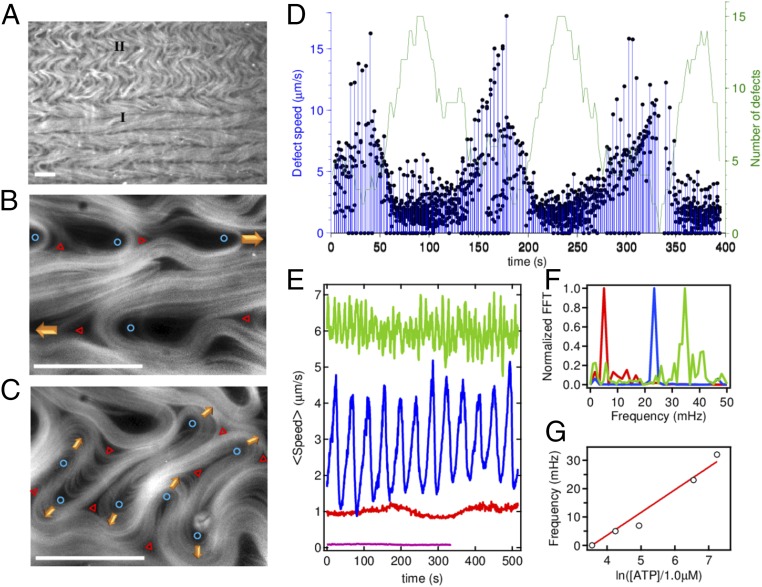
Parallel arrangement of MT bundles between defect lanes is prone to suffer the intrinsic bending instability of extensile active materials (28, 29). Indeed, we observe periodic bursts of defect creation across the stripes that lead to transient transversal flow (Fig. 2C). Regions with aligned stripes (denoted type I regions in Fig. 4A) coexist with transient regions where alignment is lost (denoted type II), which span arbitrary extensions that are commensurate with the stripe width. Close inspection shows that the instability originates from packed parallel MT bundles that bend and generate pairs of complementary half-integer defects, which either annihilate in pairs or incorporate into opposite lanes (Fig. 4 B and C and Movies S5 and S6).
Fig. 4.
Oscillatory instability of the aligned active nematic. (A–C) Fluorescence micrographs of a horizontally aligned active nematic layer showing the two alternating dynamic regimes: (I) with aligned stripes and lanes with flowing defects, and (II) with transversal flow. (B) Magnified view of regime (I) with the cores of the flowing +1/2 (blue circles) and −1/2 (red triangles) defects highlighted. (C) Magnified view of regime (II) with the proliferation of transversally flowing defect pairs. (Scale bars: 100 μm.) (D) Instantaneous defect speed, and total number of defects in a region of size of 190 × 190 μm, for an ATP concentration of 140 μM, during spontaneous alternation between type I and type II regimes. (E) Temporal evolution of the average active nematic speed, determined from velocimetry measurements for different concentrations of ATP, 1,400 μM (green), 700 μM (blue), 70 μM (red), and 35 μM (purple). (F) Normalized power spectra for data in E. (G) Linear scaling of the leading oscillation frequency with the ATP chemical potential.
We conjecture that these periodic events, which arise from the intrinsic dynamics of the sheared MTs, provide a breakdown mechanism that the active material has at its disposition to repeatedly release the extensile tensional stress accumulated in the stripes (30). An analysis of the dynamics of the aligned active nematic layer reveals that these episodes occur with remarkable regularity (Fig. 4D). Slower defects are created in bursts, accompanied by a slowing down of the flow speed. This can be understood because transversal flow encounters a much higher interfacial viscosity conditions due to the anisotropy of the aligned SmA phase. Resulting velocity oscillations are characterized by a frequency that depends linearly on the activity (Fig. 4 E–G). By considering that the rate of defect creation per unit area grows as α2 (27), combined with the fundamental length scale defined above, we obtain an intrinsic timescale for the periodic rearrangement of the aligned material, τ, that satisfies the scaling relation τ−1 ∼ α, consistent with our experimental observations (Fig. 4G). Recent numerical studies (31) have demonstrated that friction, rather than hydrodynamic coupling, can lead to the stabilization of active matter through defect ordering.
In conclusion, our work demonstrates that the disordered flow patterns of a 2D active nematic can be controlled to follow preassigned directions by means of a magnetic field, similarly to well-established strategies for the alignment of liquid crystals. The demonstrated technique, based on tailoring the anisotropy of the interface, overcomes the limitations of the protein-based active material in terms of directly addressing it with electric or magnetic fields. The described protocol enables to reversibly cycle through the different dynamic flow regimes of the kinesin/tubulin active nematic, including the usual active turbulent flow, and a laminar regime that has not been observed before in this material. The interface provides with a template for alignment that is versatile, in situ reconfigurable, and compatible with viable active subcellular materials. Once the active nematic is aligned, intrinsic length scale and timescale are clearly evidenced, providing with an invaluable tool to contrast existing and future theoretical models that ultimately aim at understanding the dynamics of the active subcellular matrix, which is known to sense the mechanical properties of its environment (32).
Materials and Methods
Protein Preparation.
MTs were polymerized from heterodimeric (α,β)-tubulin from bovine brain [a gift from Z. Dogic’s group at Brandeis University (Waltham, MA)], incubated at 37 °C for 30 min in aqueous M2B buffer (80 mM Pipes, 1 mM EGTA, 2 mM MgCl2) prepared with Milli-Q water. The mixture was supplemented with the reducing agent dithiothrethiol (DTT) (Sigma; 43815) and with guanosine-5′-[(α,β)-methyleno]triphosphate (GMPCPP) (Jena Biosciences; NU-405), a slowly hydrolysable analog of the biological nucleotide guanosine-5′-triphosphate (GTP) that completely suppresses the dynamic instability of the polymerized tubulin (33). GMPCPP enhances spontaneous nucleation of MTs (33), obtaining high-density suspensions of short MTs (1–2 µm). For fluorescence microscopy, 3% of the tubulin was labeled with Alexa 647. Drosophila melanogaster heavy-chain kinesin-1 K401-BCCP-6His (truncated at residue 401, fused to biotin carboxyl carrier protein (BCCP), and labeled with six histidine tags) was expressed in Escherichia coli using the plasmid WC2 from the Gelles Laboratory (Brandeis University) and purified with a nickel column (34). After dialysis against 500 mM imidazole aqueous buffer, kinesin concentration was estimated by means of absorption spectroscopy. The protein was stored in a 60% (wt/vol) aqueous sucrose solution at −80 °C for future use (33).
Assembly of the MT-Based Active Gel.
Biotinylated kinesin motor protein and tetrameric streptavidin (Invitrogen; 43-4301) aqueous suspensions were incubated on ice for 30 min at the specific stoichiometric ratio 2:1 to obtain kinesin–streptavidin motor clusters. MTs were mixed with the motor clusters that acted as cross-linkers, and with ATP (Sigma; A2383) that drove the activity of the gel. The aqueous dispersion contained a nonadsorbing polymeric agent (PEG, 20 kDa; Sigma; 95172) that promoted the formation of filament bundles through depletion (Fig. S1). To maintain a constant concentration of ATP during the experiments, an enzymatic ATP-regenerator system was used, consisting on phosphoenolpyruvate (PEP) (Sigma; P7127) that fueled pyruvate kinase/lactate dehydrogenase (PK/LDH) (Invitrogen; 434301) to convert ADP back into ATP. Several antioxidant components were also included in the solution to avoid protein denaturation, and to minimize photobleaching during characterization by means of fluorescence microscopy. The PEG-based triblock copolymer surfactant Pluronic F-127 (Sigma; P-2443) was added at 2% (wt/wt) (final concentration) to procure a biocompatible water/oil interface in subsequent steps.
Active Nematic Cell.
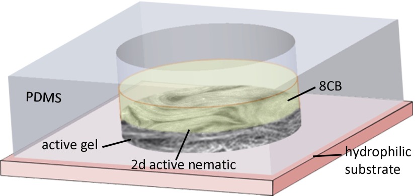
The active nematic/passive liquid crystal interface was prepared in a cylindrical pool of diameter 5 mm and depth 8 mm, manufactured with a block of poly-dimethylsiloxane (PDMS) using a custom mold. The block was glued onto a bioinert and superhydrophilic polyacrylamide-coated glass (35) (see SI Text for additional details and a sketch of the setup). The pool was first filled with 50 µL of 4-cyano-4′-octylbiphenil (8CB) (Synthon; ST01422; see Fig. S5 and SI Text for molecular structure and relevant physical properties of 8CB), and, subsequently, 1 µL of the water-based active gel was injected between the hydrophobic liquid crystal and the superhydrophilic glass plate (Fig. S6). The polymeric surfactant at the water/8CB interface ensures a planar alignment of the mesogen molecules. Samples were placed inside a thermostatic oven built with Thorlabs SM1 tube components and tape heater, and regulated with a Thorlabs TC200 controller. The system was heated up to 36 °C to promote transition to the less viscous nematic phase of 8CB, which facilitated the spreading of the active gel onto the polyacrylamide-coated substrate. After several minutes at room temperature, the active material in the gel spontaneously condensed onto the flat water/8CB interface, leading to the formation of the active nematic layer. Unlike conventional flow cells, in which a layer of the active gel is confined in a thin gap between two glass plates, this setup enabled us to use high viscosity oils to prepare the interface. The thermostatized assembly was placed in the cavity of a cylindrical permanent magnet array that provided a uniform magnetic field of up to 4 kG parallel to the substrate (see Fig. S7 and SI Text for details on the magnet setup).
Fig. S5.
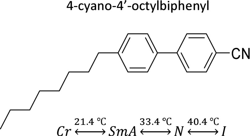
Molecular structure and phase behavior of 8CB.
Fig. S6.
Sketch of the experimental setup.
Fig. S7.
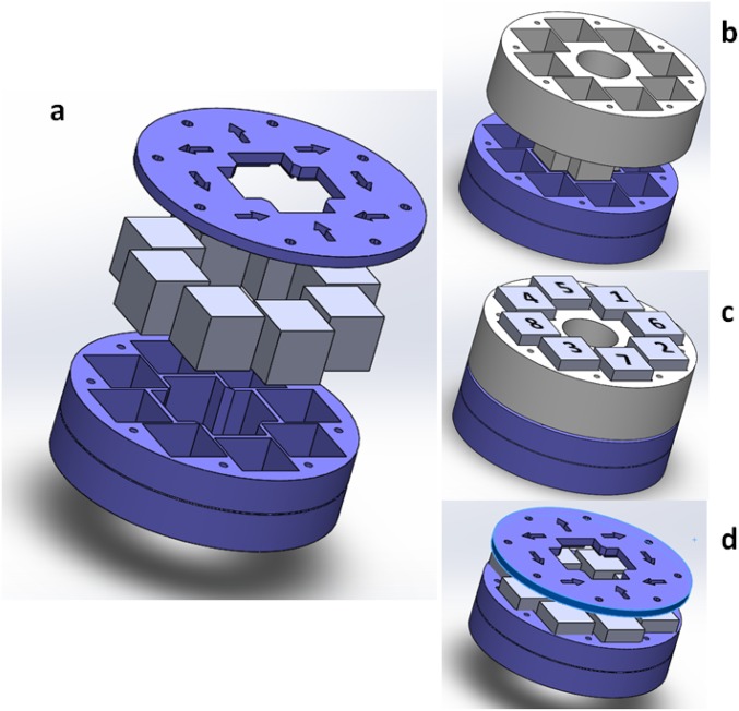
Assembly of the magnet array. (A) Arrangement of the array frame (bottom), eight cubic magnets on top, and lid cover indicating the orientation of each magnet’s orientation. (B) Placement of the magnet assembly tool and (C) suggested assembly order of the magnets for safe handling. (D) The assembly tool is finally removed and the cover can be put in place.
Sample Characterization.
Routine observations of the active nematic were performed by means of conventional epifluorescence microscopy. We used a custom-made inverted microscope with a halogen light source and a Cy5 filter set (Edmund Optics). Image acquisition was performed with a QImaging ExiBlue CCD cooled camera operated with ImageJ µ-Manager open-source software. For sharper imaging of the interfacial region, we used laser-scanning confocal microscopy with a Leica TCS SP2 equipped with a photomultiplier as detector and a HeNe–633-nm laser as light source. We performed confocal acquisition both in fluorescence and reflection modes. Whereas fluorescence confocal microscopy optimizes the signal/noise ratio for improved imaging of the interfacial material, we found that reflection confocal microscopy was optimal for image velocimetry of the active nematic due to the enhanced acquisition rate. Moreover, the latter technique can be used with label-free active nematic, thus significantly simplifying sample preparation, reducing material costs, and, more importantly, eliminating extraneous moieties that might alter the way kinesin motors walk along the MTs. Tracer-free velocimetry analysis of the active nematic was performed with a public domain particle image velocimetry (PIV) program implemented as an ImageJ plugin (36). Further analysis of raw ImageJ output data were performed with custom-written MatLab codes. Particle flow velocimetry was performed by dispersing PEG-protected polystyrene microparticles of diameter 12 μm (PEGylated polystyrene beads; Micromod; 08-56-124).
SI Text
Thermotropic Liquid Crystal.
Cyano-4′-octylbiphenil (8CB) is a thermotropic liquid crystal between 21.4 and 40.4 °C, featuring a transition from the smectic-A (SmA) to the nematic (N) phase at 33.4 °C (Fig. S5). Like most usual organic mesogens, 8CB is diamagnetic and exhibits positive diamagnetic anisotropy () (1, 37). Therefore, a magnetic field of the order of 1 kG will exert a torque that is able to align a layer of nematic 8CB.
Experimental Setup.
A block of poly-dimethylsiloxane (PDMS) with a cylindrical pool of diameter 5 mm and height 8 mm is manufactured using a custom mold (Fig. S6). The block is glued onto a bioinert and superhydrophilic polyacrylamide-coated glass, which is prepared following ref. 35. In brief, clean and activated glass is first silanized with an acidified ethanolic solution of 3-(trimethoxysilyl)propylmethacrylate (Sigma; 440159), which will act as a polymerization seed. The silanized substrates are subsequently immersed in a solution of acrylamide monomers (for at least 2 h) in the presence of the initiator ammonium persulfate (Sigma; A3678) and N,N,N′,N′-tetramethylethylenediamine (TEMED) (Sigma; T7024), which catalyzes both initiation and polymerization of acrylamide.
Design and Construction of the Permanent Magnet.
Polarizing and fluorescence microscopies are carried out in a custom-made optical setup, built around a permanent magnet assembly that provides homogeneous planar magnetic field in a region much larger than the field of view, with a maximum strength of 4 kG. The magnet is built as a Halbach cylindrical array (38) consisting on eight identical N52-grade NdFeB cubic magnets (cube size, 25.4 mm; K&J Magnetics; BX0X0X0-N52). The magnets are assembled, with the suitable geometric arrangement and magnetic moment orientation, using a 3D-printed poly-lactic acid (PLA) assembly (Fig. S7A). Stereolithography files (STL) for the three parts (frame, lid, and tool), ready to print in standard 3D printers, are available for download in www.ub.edu/socsam/AGSmA_PNAS/halbach.zip. This is an extremely cost-effective setup to generate a magnetic field that is strong and homogeneous enough to align common thermotropic mesogens. The strength of the magnetic field, which is highest at the center of the magnet array (magnet midplane is engraved as a circular groove on the frame), can be adjusted by modifying the vertical position of the sample with respect to the magnets. To facilitate the assembly, a custom tool is also recommended (gray part in Fig. S7 B and C). The suggested assembly order of the magnets is labeled on Fig. S7C. The orientation of the magnetic moment of each magnet is marked both at the bottom of the assembly frame and on the lid cover. Each magnet should be firmly pushed to the bottom of the assembly frame. Additional magnets should be approached, one at a time, to its mounting hole from below the mounting frame to minimize their attraction to already mounted magnets. Once the eight magnets are assembled, they are kept in place by their mutual repulsion. It is then safe to remove the assembly tool and to put the lid cover, which may be fastened with M4 screws. Note: hole threading for fixing lid screws, or any additional holes needed to incorporate the magnet array into an optomechanical system must be performed prior to magnet assembly. Warning: these magnets are dangerous, because they attract to ferromagnetic materials or to other magnets with unusual strength. Great care must be taken during assembly.
Supplementary Material
Acknowledgments
We thank Z. Dogic and S. DeCamp (Brandeis University), and Brandeis University Materials Research Science and Engineering Center Biosynthesis facility for their assistance in the preparation of the active gel. We thank B. Hishamunda (Brandeis University), and M. Pons and A. LeRoux (Universitat de Barcelona) for their assistance in the expression of motor proteins. We thank L. Casanellas and J. Ortín (Universitat de Barcelona) for their assistance in rheology measurements. We acknowledge helpful discussions with I. Smalyukh (University of Colorado at Boulder) and O. Lavrentovich (Kent State University) concerning the alignment of liquid crystals with magnetic fields. Funding has been provided by MINECO Project FIS 2013-41144P. P.G. acknowledges funding from Generalitat de Catalunya through a FI-DGR PhD Fellowship.
Footnotes
The authors declare no conflict of interest.
This article is a PNAS Direct Submission. N.L.A. is a guest editor invited by the Editorial Board.
This article contains supporting information online at www.pnas.org/lookup/suppl/doi:10.1073/pnas.1600339113/-/DCSupplemental.
References
- 1.Oswald P, Pieranski P. 2005. Nematic and Cholesteric Liquid Crystals: Concepts and Physical Properties Illustrated by Experiments. The Liquid Crystals Book Series (Taylor and Francis, Boca Raton, FL)
- 2.Hamley IW. 2007. Introduction to Soft Matter—Revised Edition: Synthetic and Biological Self-Assembling Materials (Wiley, Hoboken, NJ)
- 3.Strzelecka TE, Davidson MW, Rill RL. Multiple liquid crystal phases of DNA at high concentrations. Nature. 1988;331(6155):457–460. doi: 10.1038/331457a0. [DOI] [PubMed] [Google Scholar]
- 4.Sanchez T, Chen DT, DeCamp SJ, Heymann M, Dogic Z. Spontaneous motion in hierarchically assembled active matter. Nature. 2012;491(7424):431–434. doi: 10.1038/nature11591. [DOI] [PMC free article] [PubMed] [Google Scholar]
- 5.Keber FC, et al. Topology and dynamics of active nematic vesicles. Science. 2014;345(6201):1135–1139. doi: 10.1126/science.1254784. [DOI] [PMC free article] [PubMed] [Google Scholar]
- 6.DeCamp SJ, Redner GS, Baskaran A, Hagan MF, Dogic Z. Orientational order of motile defects in active nematics. Nat Mater. 2015;14(11):1110–1115. doi: 10.1038/nmat4387. [DOI] [PMC free article] [PubMed] [Google Scholar]
- 7.Surrey T, Nedelec F, Leibler S, Karsenti E. Physical properties determining self-organization of motors and microtubules. Science. 2001;292(5519):1167–1171. doi: 10.1126/science.1059758. [DOI] [PubMed] [Google Scholar]
- 8.Karsenti E, Nédélec F, Surrey T. Modelling microtubule patterns. Nat Cell Biol. 2006;8(11):1204–1211. doi: 10.1038/ncb1498. [DOI] [PubMed] [Google Scholar]
- 9.Schaller V, Weber C, Semmrich C, Frey E, Bausch AR. Polar patterns of driven filaments. Nature. 2010;467(7311):73–77. doi: 10.1038/nature09312. [DOI] [PubMed] [Google Scholar]
- 10.Köhler S, Schaller V, Bausch AR. Structure formation in active networks. Nat Mater. 2011;10(6):462–468. doi: 10.1038/nmat3009. [DOI] [PubMed] [Google Scholar]
- 11.Schaller V, Weber CA, Hammerich B, Frey E, Bausch AR. Frozen steady states in active systems. Proc Natl Acad Sci USA. 2011;108(48):19183–19188. doi: 10.1073/pnas.1107540108. [DOI] [PMC free article] [PubMed] [Google Scholar]
- 12.Sumino Y, et al. Large-scale vortex lattice emerging from collectively moving microtubules. Nature. 2012;483(7390):448–452. doi: 10.1038/nature10874. [DOI] [PubMed] [Google Scholar]
- 13.Schaller V, Bausch AR. Topological defects and density fluctuations in collectively moving systems. Proc Natl Acad Sci USA. 2013;110(12):4488–4493. [Google Scholar]
- 14.Ramaswamy S. The mechanics and statistics of active matter. Annu Rev Condens Matter Phys. 2010;1:323–345. [Google Scholar]
- 15.Marchetti MC, et al. Hydrodynamics of soft active matter. Rev Mod Phys. 2013;85(3):1143. [Google Scholar]
- 16.Gao T, Blackwell R, Glaser MA, Betterton MD, Shelley MJ. Multiscale polar theory of microtubule and motor-protein assemblies. Phys Rev Lett. 2015;114(4):048101. doi: 10.1103/PhysRevLett.114.048101. [DOI] [PMC free article] [PubMed] [Google Scholar]
- 17.Zhou S, Sokolov A, Lavrentovich OD, Aranson IS. Living liquid crystals. Proc Natl Acad Sci USA. 2014;111(4):1265–1270. doi: 10.1073/pnas.1321926111. [DOI] [PMC free article] [PubMed] [Google Scholar]
- 18.Oswald P, Pieranski P. 2006. Smectic and Columnar Liquid Crystals: Concepts and Physical Properties Illustrated by Experiments. The Liquid Crystal Book Series (Taylor and Francis, Boca Raton, FL)
- 19.Henkin G, DeCamp SJ, Chen DT, Sanchez T, Dogic Z. Tunable dynamics of microtubule-based active isotropic gels. Philos Trans A Math Phys Eng Sci. 2014;372(2029):20140142. doi: 10.1098/rsta.2014.0142. [DOI] [PMC free article] [PubMed] [Google Scholar]
- 20.Julicher F, Kruse K, Prost J, Joanny J. Active behavior of the cytoskeleton. Phys Rep. 2007;449(1-3):3–28. [Google Scholar]
- 21.Kruse K, Joanny JF, Jülicher F, Prost J, Sekimoto K. Generic theory of active polar gels: A paradigm for cytoskeletal dynamics. Eur Phys J E Soft Matter. 2005;16(1):5–16. doi: 10.1140/epje/e2005-00002-5. [DOI] [PubMed] [Google Scholar]
- 22.Prost J, Jülicher F, Joanny JF. Active gel physics. Nat Phys. 2015;11:111–117. [Google Scholar]
- 23.Giomi L, Bowick MJ, Ma X, Marchetti MC. Defect annihilation and proliferation in active nematics. Phys Rev Lett. 2013;110(22):228101. doi: 10.1103/PhysRevLett.110.228101. [DOI] [PubMed] [Google Scholar]
- 24.Shi XQ, Ma YQ. Topological structure dynamics revealing collective evolution in active nematics. Nat Commun. 2013;4:3013. doi: 10.1038/ncomms4013. [DOI] [PMC free article] [PubMed] [Google Scholar]
- 25.Thampi SP, Golestanian R, Yeomans JM. Velocity correlations in an active nematic. Phys Rev Lett. 2013;111(11):118101. doi: 10.1103/PhysRevLett.111.118101. [DOI] [PubMed] [Google Scholar]
- 26.Weber CA, Bock C, Frey E. Defect-mediated phase transitions in active soft matter. Phys Rev Lett. 2014;112(16):168301. doi: 10.1103/PhysRevLett.112.168301. [DOI] [PubMed] [Google Scholar]
- 27.Giomi L. Geometry and topology of turbulence in active nematics. Phys Rev X. 2015;5(3):031003. [Google Scholar]
- 28.Aditi Simha R, Ramaswamy S. Hydrodynamic fluctuations and instabilities in ordered suspensions of self-propelled particles. Phys Rev Lett. 2002;89(5):058101. doi: 10.1103/PhysRevLett.89.058101. [DOI] [PubMed] [Google Scholar]
- 29.Voituriez R, Joanny JF, Prost J. Spontaneous flow transition in active polar gels. Europhys Lett. 2005;70(3):404. [Google Scholar]
- 30.Giomi L, Mahadevan L, Chakraborty B, Hagan MF. Excitable patterns in active nematics. Phys Rev Lett. 2011;106(21):218101. doi: 10.1103/PhysRevLett.106.218101. [DOI] [PubMed] [Google Scholar]
- 31.Doostmohammadi A, Adamer MF, Thampi SP, Yeomans JM. Stabilization of active matter by flow-vortex lattices and defect ordering. Nat Commun. 2016;7:10557. doi: 10.1038/ncomms10557. [DOI] [PMC free article] [PubMed] [Google Scholar]
- 32.Gupta M, et al. Adaptive rheology and ordering of cell cytoskeleton govern matrix rigidity sensing. Nat Commun. 2015;6:7525. doi: 10.1038/ncomms8525. [DOI] [PMC free article] [PubMed] [Google Scholar]
- 33.Hyman AA, Salser S, Drechsel DN, Unwin N, Mitchison TJ. Role of GTP hydrolysis in microtubule dynamics: Information from a slowly hydrolyzable analogue, GMPCPP. Mol Biol Cell. 1992;3(10):1155–1167. doi: 10.1091/mbc.3.10.1155. [DOI] [PMC free article] [PubMed] [Google Scholar]
- 34.Subramanian R, Gelles J. Two distinct modes of processive kinesin movement in mixtures of ATP and AMP-PNP. J Gen Physiol. 2007;130(5):445–455. doi: 10.1085/jgp.200709866. [DOI] [PMC free article] [PubMed] [Google Scholar]
- 35.Lau AWC, Prasad A, Dogic Z. Condensation of isolated semi-flexible filaments driven by depletion interactions. Europhys Lett. 2009;87(4):48006. [Google Scholar]
- 36.Tseng Q, et al. Spatial organization of the extracellular matrix regulates cell-cell junction positioning. Proc Natl Acad Sci USA. 2012;109(5):1506–1511. doi: 10.1073/pnas.1106377109. [DOI] [PMC free article] [PubMed] [Google Scholar]
- 37.Kléman M, Lavrentovich OD. Soft Matter Physics: An Introduction. Partially Ordered Systems. Springer; New York: 2003. [Google Scholar]
- 38.Soltner H, Blümler P. Dipolar Halbach magnet stacks made from identically shaped permanent magnets for magnetic resonance. Concepts Magn Reson Part A Bridg Educ Res. 2010;36A(4):211–222. [Google Scholar]
Associated Data
This section collects any data citations, data availability statements, or supplementary materials included in this article.


