Abstract.
The emerging technique of rapid prototyping with three-dimensional (3-D) printers provides a simple yet revolutionary method for fabricating objects with arbitrary geometry. The use of 3-D printing for generating morphologically biomimetic tissue phantoms based on medical images represents a potentially major advance over existing phantom approaches. Toward the goal of image-defined phantoms, we converted a segmented fundus image of the human retina into a matrix format and edited it to achieve a geometry suitable for printing. Phantoms with vessel-simulating channels were then printed using a photoreactive resin providing biologically relevant turbidity, as determined by spectrophotometry. The morphology of printed vessels was validated by x-ray microcomputed tomography. Channels were filled with hemoglobin (Hb) solutions undergoing desaturation, and phantoms were imaged with a near-infrared hyperspectral reflectance imaging system. Additionally, a phantom was printed incorporating two disjoint vascular networks at different depths, each filled with Hb solutions at different saturation levels. Light propagation effects noted during these measurements—including the influence of vessel density and depth on Hb concentration and saturation estimates, and the effect of wavelength on vessel visualization depth—were evaluated. Overall, our findings indicated that 3-D-printed biomimetic phantoms hold significant potential as realistic and practical tools for elucidating light–tissue interactions and characterizing biophotonic system performance.
Keywords: three-dimensional printing, tissue phantoms, hyperspectral reflectance imaging, oximetry
1. Introduction
A wide variety of tissue-simulating phantoms have been developed and utilized to study emerging biophotonic diagnostic techniques. Phantoms are useful for generating information on light–tissue interactions and device working mechanisms, as well as for device performance intercomparison, quality control, calibration, and standardization during clinical use. The vast majority of biophotonic phantoms have involved homogeneous regions or layered structures, containing well-characterized chromophores and scatterers and basic geometric inclusions, such as spheres or cylinders.1,2 Phantoms are typically composed of liquid samples, hydrogels, or polymers such as polydimethylsiloxane and epoxy. These relatively simple and idealized approaches are effective for generating basic information on device operation and performance. However, the clinical relevance of these results may be questionable due to the lack of biologically relevant morphology. In recent studies, there have been increasing efforts to develop tissue phantoms with more complex morphology that can provide insights into clinical issues, such as the effect of device and tissue parameters on performance in measuring diagnostic parameters3,4 (e.g., spatial dimensions of tissue structures indicative of disease onset/progression). These approaches may also provide more useful methods for guiding device development and enabling objective device performance assessment and intercomparison. Therefore, biomimetic phantoms hold significant potential for a wide range of biophotonic diagnostic technologies.
One of these modalities—hyperspectral reflectance imaging (HRI)—has been a useful tool for near-surface imaging of key tissue chromophores, such as oxyhemoglobin () and deoxyhemoglobin (HHb), and determination of hemoglobin saturation levels (). HRI has been studied for monitoring blood perfusion in superficial tissues such as skin wounds,5 diagnosis of ocular vascular disorders,6,7 tumor vasculature oximetry for cancer prognosis,8,9 artery–vein differentiation during surgery,10 and subcutaneous vasculature visualization for vein inspection and blood withdrawal.11
HRI studies have used phantoms incorporating hemoglobin (Hb) in various ways to verify device performance. For example, a homogeneous liquid phantom incorporating porcine blood at a range of Hb saturation levels was implemented for quantitative evaluation of an HRI system.12 Phantoms with submillimeter channel geometry and capability for varying saturation levels have been fabricated using components such as straight, thin-walled glass capillary tubes embedded in silicone, resin, or polyurethane.1,2 However, phantoms incorporating biomimetic vascular geometries may enable a more thorough understanding of the effect of tissue morphology on oximetry measurement accuracy, as well as other tissue and device parameters (e.g., wavelength) that influence device performance. Furthermore, such phantoms may enable more realistic assessment and comparison of HRI system performance.
In recent years, there have been increasing efforts to generate biophotonic phantom structures with tissue-mimicking microfluidic channels based on digitally processed clinical images of tissues, using techniques such as photolithography and silicone molding13 or laser micromachining.14 However, these techniques represent a high degree of complexity and relatively high fabrication costs. Additive manufacturing represents a promising approach that has been advancing rapidly, providing revolutionary strategies for arbitrary structure fabrication. Three-dimensional (3-D) printing, in particular, has undergone improvements resulting in reduced system cost, better resolution, and a wider selection of printing materials. As a result, 3-D printing has the potential to become a widespread, practical method for fabrication of complex biomimetic phantoms.
There is a growing body of research involving the processing of clinical tissue images into templates for 3-D-printing tissue-mimicking structures for medicine and research.14–18 Patient-specific phantoms have been generated based on magnetic resonance imaging and computed tomography (CT) images,15,17 and used to enhance visualization of vascular tissue pathologies such as intracranial artery stenosis as well as for clinical treatment planning of endovascular aneurysm repair surgery. Also, CT-based 3-D-printed biomimetic phantoms incorporating realistic vasculature have been utilized for applications such as ultrasound pulse wave imaging assessment and computational model validation.18 Furthermore, fabrication of customized implantable devices based on 3-D medical images are becoming increasingly commonplace.15,16,19,20 Approaches developed in these studies can be adapted to advance phantom development in biophotonics.
While 3-D-printing has seen little application in biophotonics, one study describes the fabrication of samples with complex surface profiles for curvature calibration in spatial-frequency-domain imaging.21 In our recent work, we investigated two popular 3-D printing techniques, fused deposition modeling and stereolithography (SLA), for fabricating turbid phantoms containing cylindrical channels.22 Phantoms of various diameters (0.2 to 1.5 mm) and depths (0.4 to 2.0 mm) were printed and characterized in terms of morphology and optical properties. Viable phantoms were injected with nanoparticle contrast agents and imaged with HRI. Phantoms fabricated with the SLA printer indicated the most promise due to their high-resolution patent channels and biologically relevant optical properties.
The purpose of the current study was to advance methods for technological development and standardized performance assessment of biophotonic devices. Specific goals included identifying approaches for fabricating and validating image-defined, 3-D-printed phantoms, as well as providing an initial evaluation and demonstration of their utility through HRI-based oximetry measurements. These preliminary measurements also provided insights into relevant light–tissue interactions and basic performance of HRI devices (e.g., penetration depth and oximetry accuracy).
2. Material and Methods
This study—an overview of which is shown in Fig. 1—builds on prior work in which a clinical fundus image was segmented into a digital vessel network.14 The current project involved identification of optimal 3-D printing parameters, printing of vascular network phantoms, and near-infrared HRI of Hb-filled phantoms. Imaging was performed to estimate temporally varying distributions.
Fig. 1.
Phantom fabrication and preparation procedure, from left to right: human retinal vasculature fundus image, two-dimensional (2-D) segmented vascular map14 (© 2012 OSA. Reprinted with permission from the Optical Society of America), three-dimensional (3-D)-printed vascular phantom with hemoglobin (Hb)-filled channel, and hyperspectral reflectance imaging (HRI) result processed to estimate oxyhemoglobin () concentration.
2.1. Phantom Design, Fabrication, and Preparation
In the aforementioned prior work, a human retinal vasculature image was captured by a commercial fundus camera (Fig. 1). This image was segmented to generate a digital geometric model of a two-dimensional (2-D) vascular network with varying vessel size and density. The segmentation process involved image enhancement and thresholding-based conversion to a binary map using Adobe Photoshop® software (Adobe Systems Inc., San Jose, California). In order to convert this 2-D planar model into a full 3-D representation and incorporate circular vessel cross sections, several 2-D maps were edited using a morphological image erosion technique, and stacked with -spacing to vary inplane vessel width, resulting in vertically discretized circular channel profiles. The final design was converted into the stereolithographic file format using MATLAB® for 3-D printing.
An SLA 3-D printer (Form , FormLab, Somerville, Massachusetts) was used to fabricate phantoms for this study. This printer consists of three major parts: an ultraviolet (UV) beam scanner, a resin tank, and a building stage. The UV beam scanner fabricates thin layers of cured photoreactive resin (based on the object’s initial design in the plane, parallel to the building stage) to form the entire 3-D shape of an object. Prior to printing, a gentle shaking of the resin container was performed to prevent particle settling. During the printing process, drops of resin are exposed to the focused UV light, resulting in crosslinking and formation of a solid, polymerized structure. After the formation of each layer, the building stage translates in the direction within the resin tank. The 3-D printer provides a nominal feature size resolution of and user-selectable layer thicknesses of 25, 50, or . We found the resolution setting to be optimal for this study. The printing speed is fixed based on the nominal selected layer resolution ( in this case). Several stock materials incorporating different color pigments and turbidity levels were used (FormLab, Somerville, Massachusetts).
There are a number of fabrication challenges to printing phantoms with channels of submillimeter diameters and arbitrarily irregular orientation and shape. First of all, removing uncured resin from irregular channels is both essential and difficult to accomplish effectively. Phantoms were cleaned by repeated flushing of the channels with isopropanol solution. Second, the smallest size and depth of 3-D-printed vascular channels were limited by the 3-D printer capability. To evaluate this limit, we printed a phantom with seven cylindrical channels having nominal diameters and depths of 0.5 to 1.1 mm and 350 μm, respectively. Printing was repeated three times for different channel orientations with respect to the printing bed: parallel, perpendicular, and 45 deg. An x-ray microtomography, or , system (SCANCO Medical 100, Switzerland) was used to evaluate the quality of printed phantom morphology.
Ensuring that phantom optical properties are biologically relevant is a critical part of demonstrating tissue phantom suitability. Toward this end, we printed thin slabs () and characterized their optical properties using spectrophotometry. Diffuse transmittance and reflectance were measured in the wavelength range of 400 to 1200 nm with a 5 nm interval using a dual-beam integrating sphere spectrophotometer (Lambda 1050, Perkin Elmer, Waltham, Massachusetts). The absorption coefficient, , and reduced scattering coefficient, , were calculated at each wavelength from the measured transmittance and reflectance, using the inverse adding-doubling method.23
To mimic the optical properties of blood, we utilized a commercially available human solution for calibrating CO-oximeters (Multi-4™ L2, Instrumentation Laboratory Co., Bedford, Massachusetts), which contains a total Hb concentration in the normal range of human blood (). Yeast, an oxygen-consuming microorganism, can be added to this solution to induce dynamic desaturation, the conversion of to HHb.24 Solutions of and yeast were injected into the vascular channels of the phantoms for HRI measurement.
2.2. Hyperspectral Reflectance Imaging System
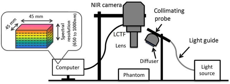
A diagram of our near-infrared HRI system, which was described briefly by Wang et al.,22 is shown in Fig. 2. It uses a 100 W quartz tungsten–halogen fiber-optic light source (Oriel Instruments, Stratford, Connecticut) for illumination. The illumination light was delivered through a liquid light guide (Newport Corporation, Irvine, California) of 5 mm diameter, collimated and expanded to a beam diameter of 15 mm, and homogenized using a diffuser before applying to the sample. The reflected light from the sample was collected through a macrovideo zoom lens (18–108 mm focal length, , Edmund Optics, Barrington, New Jersey), collimated by a 5 mm lens, then filtered by a liquid crystal tunable filter (LCTF, CRI Varispec, Perkin Elmer, Waltham, Massachusetts), working in the range of 650 to 1000 nm, with bandwidths of 7 to 10 nm. Filtered light was detected by a Peltier-cooled, high-sensitivity, visible–near-infrared CCD camera (Pixis 1024, Princeton Instruments, Trenton, New Jersey). A LabView interface was used to control the LCTF and the camera (wavelength range, wavelength step size, and exposure time).
Fig. 2.
Diagram of the HRI system.
2.3. Imaging Procedure and Data Processing
Reflectance images of pixels over a field of view were taken sequentially in the wavelength range of 650 to 1000 nm at 10 nm intervals. For each experiment, reference images of a Spectralon® standard of similar size to the phantom were taken using the same experimental settings as in phantom imaging. Data were then analyzed using custom routines written in MATLAB®. The algorithm is briefly described as follows: (1) Raw reflectance images were normalized by reference standard images, wavelength by wavelength, to remove spectral signal variations due to system/equipment properties and to correct for illumination nonuniformity; (2) binning was applied to the normalized images to reduce noise; (3) an absorbance spectrum, , was calculated for each pixel as25
| (1) |
where is the reduced scattering coefficient of the phantom material, is the normalized reflectance, and is the wavelength; and (4) based on the known extinction coefficient of each chromophore (), the relative concentration of each component was then solved using a non-negative least squares (NNLS) algorithm26 for each pixel of the image,
| (2) |
where resin denotes cured resin (phantom matrix) and Corr is a constant correction factor, is pathlength, is the known components extinction coefficient matrix, and is the unknown fractional contribution matrix. was calculated using the solved and HHb amounts,
| (3) |
2.4. Hyperspectral Reflectance Imaging Measurements
The HRI system and 3-D-printed phantoms with Hb-filled channels were utilized for oximetry measurements. Three different experimental schemes were followed, as listed in Table 1.
Table 1.
Hyperspectral reflectance imaging (HRI) vascular phantom experimental schemes.
| Configuration | Vascular phantom | Channel solution | |
|---|---|---|---|
| 1 | One-layer | Oxyhemoglobin yeast | |
| 2 | Two-layer | Top layer | yeast |
| Bottom layer | 100% | ||
| 3 | Two-layer | Top layer | 100% |
| Bottom layer | yeast | ||
| 4 | One-layer with tilted channel | yeast | |
To evaluate the results of HRI oximetry, spectroscopic measurements (Lambda 1050, Perkin Elmer, Waltham, Massachusetts) were also performed on samples extracted from the same batch used to fill phantom channels (1.3 mm diameter, 350 μm to 3 mm depth with 5 mm separation between cylindrical channels). Desaturation over time was then calculated from spectrophotometry data, and results were correlated with the HRI-generated estimates. Three separate measurements showed a mean difference of 8% between corresponding timepoints, indicating moderately good agreement, with differences possibly due to the simplicity of our oximetry estimation algorithms, absorption by the matrix material, or variations in the yeast oxygen consumption rate.
3. Results and Discussion
3.1. Phantom Optical Properties
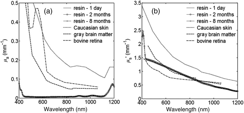
Different off-the-shelf photoreactive resins were analyzed through optical property measurements before selecting the optimal material, and no additional materials (chromophores and scatterers) were added. Results were compared with optical properties of biological tissues such as bovine retina,27 gray brain matter,28 and Caucasian skin29 (Fig. 3). The 3-D printer manufacturer's "white" resin was shown to provide biologically relevant scattering levels, and thus was selected for use in the remainder of the measurements in this study. The formulation of this resin, including pigment and additive concentrations, is proprietary and thus was not available to the authors. To further investigate the white resin’s scattering properties, a clear photoreactive resin (FormLabs, Somerville, Massachusetts) was obtained, and different concentrations of titanium dioxide () particles (Sigma Aldrich, Saint Louis, Missouri) were added. Turbidity levels of the prepared samples were measured using spectrophotometry. The clear resin with 0.05% by weight showed a similar scattering distribution as that obtained from the white resin; the root mean square error (RMSE) between these two distributions was over the wavelength range of 650 to 1000 nm based on 5 nm intervals. White resin showed a lower absorption than biological tissues; however, Hb was added in phantom channels to provide a biologically relevant chromophore. Polymerized resin optical property stability was shown to be excellent over a period of eight months (Fig. 3). An RMSE of for and 0.024 mm−1 for was observed between the first and last measurements in the wavelength range of 650 to 1000 nm at 5 nm intervals.
Fig. 3.
(a) Absorption coefficient and (b) reduced scattering coefficient of a white 3-D-printed slab. Results of measurements over a period of 8 months after 3-D printing are compared to biological tissues.27–29
3.2. Phantom Morphology Validation
The results of our printing quality assessment in cylindrical channel phantoms are shown in Table 2. Samples were printed in three orientations: horizontal, 45 deg, and vertical with respect to the printing bed. Horizontally oriented channels showed the poorest printing quality among these samples. The printer failed to create patent channels when the specified diameter was less than . The smallest patent channel achievable was measured at in diameter, and an average size deviation of from the designed values was observed. Vertically oriented channels were the highest quality, with the smallest patent channel having a diameter of , and the average size deviation between the 3-D-printed channels and the designed parameters measured as .
Table 2.
Geometry validation results: cylindrical channel phantoms.
| Straight channel phantom | Channel size () | ||||||
|---|---|---|---|---|---|---|---|
| Designed | 500 | 600 | 700 | 800 | 900 | 1000 | |
| Measured for different printing orientations | Horizontal | Not patent | Not patent | Not patent | Not patent | 500 | 700 |
| 45 deg | Not patent | Not patent | 550 | 600 | 850 | 850 | |
| Vertical | Not patent | 450 | 650 | 750 | 900 | 1000 | |
Two different phantoms incorporating image-based vascular structures were designed and fabricated. Geometry validation was performed using imaging and advanced visualization software (3-D Slicer, Isomics Inc., Cambridge, Massachusetts; Netfabb GmbH, Lupburg, Germany). A set of images captured from a defective two-layer vascular phantom is shown in Fig. 4. Areas with unshaped channels and surface leakage are marked in the cross-sectional images [Figs. 4(a) and 4(b)]. Several factors such as printer resolution limitations, poor channel cleaning, air bubble accumulation in the resin tank, or sample orientation may result in an imperfect product. Another set of cross-sectional images and a 3-D view of an intact two-layer phantom, printed under the identical specifications and conditions as before, are shown in Fig. 5. Table 3 shows validation results for both one- and two-layer phantoms. For the one-layer vascular network phantom, a minimum channel thickness (height) of was achieved and channels were consistently formed deeper and with smaller size than designed. While simple cylindrical channels printed in an orientation perpendicular to the printing show a mean error of of 8% (Table 2, cylindrical channel phantom), phantoms printed in arbitrary orientations have lower resolution due to layer thickness limitations. Even with these larger diameter channels, the two-layer phantom channels proved difficult to fill with Hb solution in a reasonable time frame and thus were increased in diameter slightly (830 to ; Table 3) to facilitate this process. The results illustrate the potential variability in samples fabricated with features approaching the printer resolution limit and indicate the necessity of using a nondestructive imaging method (e.g., ), to ensure 3-D-printed phantom quality.
Fig. 4.
-Computed tomography () validation of a defective phantom: (a) cross-sectional image of two-layer phantom, arrows point to the unshaped channels; (b) cross-sectional image from the same phantom with a surface leakage, where the arrow points to the leaking area; and (c) 3-D view with bottom layer omitted for clarity.
Fig. 5.
validation of viable phantoms: cross-sectional images of (a) one-layer and (b) two-layer vascular phantoms and (c) a 3-D view of the two-layer phantom.
Table 3.
Geometry validation results: vascular phantoms.
| One-layer phantom | Two-layer phantom | |||||
|---|---|---|---|---|---|---|
| Parameter | Designed | Measured | Top layer | Bottom layer | ||
| Designed | Measured | Designed | Measured | |||
| Channel thickness () | 1300 | 750 | 1600 | 830 | 1600 | 920 |
| Channel depth () | 350 | 750 | 350 | 850 | 2300 | 2760 |
3.3. Oximetry in One-layer Phantom
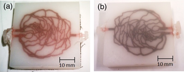
The one-layer vascular phantom was filled with a solution of and 2% yeast (Table 1, configuration 1). Photographs of this phantom 30 and 120 min after solution injection are shown in Fig. 6. The change in apparent color of the Hb solution qualitatively suggests that desaturation has occurred.
Fig. 6.
Photographs of one-layer vascular phantom at (a) 30 min and (b) 120 min after solution injection.
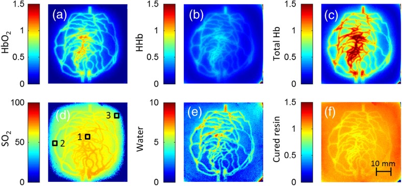
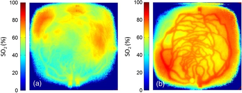
HRI measurements were performed for 30 time points over about 6 h (until oxygenation change of was observed over 30 min) to monitor the process of desaturation. From each set of HRI spectral images, an absorbance map was calculated [Eq. (1)] and fractional contributions of the primary chromophores–, HHb, water, and cured resin—were solved using a spectral unmixing NNLS algorithm [Eq. (2)]. A set of images derived from HRI data captured 75 min after adding yeast to the solution is shown in Fig. 7. Figure 8 shows calculated absorbance spectra as well as chromophore contribution fitting results for channel regions with high- and low-channel densities and a nonchannel region of the same phantom. The map [Fig. 7(d)] is marked with three regions of interest (ROIs), representing (1) high-channel density, (2) low-channel density, and (3) nonchannel regions, which indicate the location of spectral data presented in Fig. 8.
Fig. 7.
One-layer phantom chromophore concentrations and saturation maps 75 min after adding the solution: (a) , (b) deoxyhemoglobin (HHb), (c) total Hb, (e) water, and (f) cured resin. The hemoglobin saturation levels () map (d) is marked with three regions of interest (ROIs) used to generate results in Fig. 8.
Fig. 8.
Sample HRI spectral data measured from the one-layer vascular phantom 75 min after solution injection, including absorbance curves for regions with (a) high- and low-channel densities and nonchannel area (the effect of phantom matrix is removed from the absorbance data for demonstration purpose) and (b–d) chromophore contributions after NNLS unmixing. Results are shown for channel regions with (b) relatively high and (c) low densities, and (d) a nonchannel area.
In locations where phantom channel density was greatest, higher , HHb, and total Hb concentrations tended to be measured within the channels. This is due to the interaction of diffuse photons with a larger fractional volume of Hb-filled channels; similar variations in estimated chromophore contribution are also seen in Figs. 8(b) and 8(c). The influence of channel density can be observed in the map (Fig. 7) as well, though to a lesser extent. Higher values tended to be measured in regions of greater vessel density—the maximum variation in with vessel density was approximately 6%, 13%, and 17% at mean saturation levels of 65%, 40%, and 12%, respectively. This variation may indicate a minor spectral attenuation effect or a spectral unmixing error with Hb concentration. Alternately, some of this variation may be attributable to differences in yeast and dissolved oxygen content stemming from the injection process, which can take up to 15 min to completely fill all channels. Since the phantom was filled with an Hb solution from one batch, yeast concentration remains almost uniform within the phantom channels.
In spite of a lack of Hb in nonchannel locations, calculations indicated some residual Hb concentration in these regions, due to scattered light being absorbed in adjacent channel regions. The distribution in Fig. 7(d) shows a saturation range of 50% to 65% in nonchannel regions due to the aforementioned scattering from adjacent channels combined with the fact that this is a ratiometric parameter where both components of the ratio are similarly low. A sharp drop-off in is seen toward the edges of the phantom; this is essentially an unmixing artifact caused by crosstalk between the HHb and resin absorbance signatures. No absorption is seen in this region, yet HHb concentration is nonzero, which leads to a zero oxygenation value.
To further investigate light propagation in regions with different channel densities, a 3-D-printed phantom incorporating 14 parallel cylindrical channels with 1.3 mm diameters and varied regional densities (with edge-to-edge channel spacing of 0.2 to 2.5 mm) was designed and fabricated. HRI was performed on this phantom with Hb–yeast solution-filled channels. For ROIs in both channel and nonchannel locations, higher absorbance and chromophore content estimates were observed in areas where channel density was greater, similar to results in vascular phantoms. Also, levels were calculated for ROIs with different channel densities and compared with spectrophotometry data. Comparing HRI measurements of ROIs with different channel densities showed a maximum difference of for a mean saturation level of 45%.
3.4. Oximetry in Two-Layer Phantom
Biological tissue contains blood vessels of varied saturation levels (e.g., arteries and veins) at a range of depths. Toward accurate representation of these characteristics, the vascular networks in the two-layer phantom were each filled with a different Hb solution (Table 1, configurations 2 and 3). HRI was conducted on the phantom for each experimental configuration, and data were recorded for more than 30 time points over about 8 h.
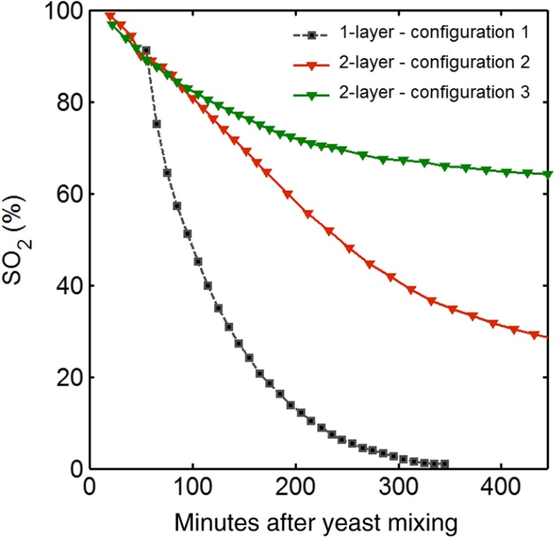
Links to the transient results for two-layer phantoms are provided in Fig. 9, with the still images representing data acquired 4 h after filling phantom channels with the Hb solution. For the experimental configuration 2, both the top and bottom layers are fully oxygenated at the beginning of the experiment. Therefore, the video starts with a fully saturated frame (). The level decays gradually due to the yeast oxygen consumption in the top layer channels (channel region final mean ). Inhomogeneities seen in the frames are primarily correlated with channel morphology, with higher values seen in regions where fewer superficial layer vessels are located. Similarly, for experimental configuration 3, the video starts with an almost fully saturated frame () and continues toward desaturation more quickly in nonvessel areas (channel region final mean ). Since HRI is more sensitive to superficial channels, a higher equilibrium saturation level is observed at the final time point compared with configuration 2. Desaturation of Hb solution inside the deeper channels over time lowers perceived values of the bulk phantom. Additionally, it is noteworthy that the highly saturated superficial vasculature is readily visible against the lower saturation background in Fig. 9(b) (Video 2); however, in Fig. 9(a) (Video 1), the desaturated superficial vasculature does not appear with high contrast against the highly oxygenated background. This phenomenon will require further elucidation in future studies.
Fig. 9.
Desaturation over time was calculated from a channel region in the HRI images for both one- and two-layer phantoms (Fig. 10). Solutions in the variable layer started from near 100% saturation and constantly decreased until they reached a stable level, where almost all had apparently been converted to HHb. The equilibrium saturation level for configuration 1 was almost zero percent ( dropped from 90% to 0% over 6 h), while in the two-layer phantom, a significantly higher saturation was observed at the equilibrium state ( and for configurations 2 and 3, respectively), due to the presence of a constantly oxygenated vascular layer. Comparing the saturation levels of the configurations 2 and 3 shows that the system was roughly twice as sensitive to the saturation level of the top layer as to the bottom layer.
Fig. 10.
Phantoms oxygen desaturation over time. In configurations 2 and 3, values are fixed at approximately 100% in the bottom and top layers, respectively.
3.5. Spectral Variations in Penetration Depth
Due to the decrease in scattering with wavelength, variations in visualization of deeper channels were noted in two-layer phantom experiments. Normalized reflectance images at and and a corresponding saturation map (experimental configuration 2, desaturated stable state) are shown in Fig. 11 (Video 3), along with spectrally varying reflectance images over this range at 10 nm intervals. Reflectance images at longer wavelengths show improved visualization of channels. Arrows show the location of a second-layer channel filled with highly oxygenated Hb solution. This channel was not covered by the first layer vascular mesh; thus diffuse reflectance from this channel was less affected by the first vascular layer. Consequently, an inhomogeneity in the saturation map was seen after full desaturation of the first layer. This result illustrates the potential to use wavelength-specific or narrow-band imaging to complement and elucidate measurements performed with HRI.
Fig. 11.
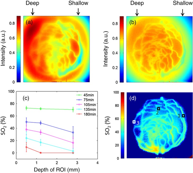
As a further investigation of depth selectivity and wavelength dependence in HRI, a phantom incorporating a tilted vascular array was designed and fabricated with 3-D printing. Channel depth varied from 0.5 to 2.8 mm in this phantom, as verified by imaging. Channels of the phantom were filled with a Hb-yeast solution (Table 1, configuration 4). HRI was conducted on the phantom and data were recorded for more than 3 h in order to study different levels. Figure 12 shows results from these experiments, including representative reflectance images, a representative map, and a graph of estimated levels as a function of network region depth and time. A greater depth of penetration and better vessel visualization were found at longer wavelengths as illustrated in Figs. 12(a) and 12(b). Also, a significant deviation between the levels of channels located at different depths was observed [Fig. 12(c)]. An underestimation of levels for deeper areas was observed.
Fig. 12.
Vascular phantom with tilted channels: normalized reflectance images at (a) 650 nm and (b) 1000 nm; (c) level versus depth for different time points after adding yeast to Hb solution; and (d) map at 105 min after adding yeast to the Hb solution [ROIs used to generate the graph (c) are marked on the map].
In order to provide a more idealized investigation of the effect of depth variation on HRI measurements, experiments were repeated in a 3-D-printed phantom with eight cylindrical channels with diameters of 1.3 mm at depths from 0.35 to 3.5 mm. A decrease in channel contrast and predicted chromophore content versus depth was observed due to limited light penetration. For instance, the estimated contribution of the 3-mm-deep channel were three and four times smaller than those for the shallowest channel at 99% and 60% Hb saturation levels, respectively. Consequently, a decrease of calculated levels was also seen for deeper channels at different time points, similar to the results of the tilted vascular phantom. A maximum 14% deviation from the mean value was observed among 10 measurements performed at Hb saturation levels between 99% and 0%. The variation in with depth may be due, at least in part, to the defocusing effect of scattering for deeper channels, which reduces the intensity of the maximum pixels in the deeper channels compared with shallower ones.
4. Conclusion
We have performed an initial evaluation of the feasibility of rapid prototyping for producing stable, biologically relevant vascular phantoms for biophotonics based on medical images. Factors including 3-D printer settings, printing materials, sample orientation, and phantom geometry must be considered and the printed samples validated (e.g., using imaging) to ensure high-quality phantom fabrication. Overall, our results indicate that 3-D-printed phantoms have potential as standardized tools for assessing the performance of HRI-based and other optical diagnostic devices, as well as for generating insights into light–tissue interactions and device working mechanisms which may lead to improvements in clinical effectiveness. Future improvements in printing resolution and optical property customization will further improve the utility of this approach.
Acknowledgments
The authors would like to thank Dr. Srinidhi Nagaraja, Dr. Maureen Dreher, and Dr. Maria Iacono for their help with imaging and 3-D visualization. The authors gratefully acknowledge funding support from the Food and Drug Administration (FDA) Critical Path Initiative, the National Science Foundation’s FDA Scholar-in-Residence program (NSF, CBET-1238407), and the University of Maryland’s Center for Excellence in Regulatory Science and Innovation.
Disclaimer: The mention of commercial products, their sources, or their use in connection with material reported herein is not to be construed as either an actual or implied endorsement of such products by the Department of Health and Human Services.
Biographies
Pejhman Ghassemi received a BS in electrical engineering from Azad University of Tehran, MS and PhD degrees in biomedical engineering from Tarbiat Modares University of Tehran, Iran. He also received a PhD degree in electrical engineering from the Catholic University of America in 2014. In 2014, he joined the U.S. Food and Drug Administration Optical Diagnostic Devices Laboratory as a postdoctoral fellow. His research focuses on biophotonic imaging and laser thermal safety analysis.
Jessica C. Ramella-Roman received an electrical engineering degree from the University of Pavia, Italy, in 1993. She received a MS and PhD degree in electrical engineering from Oregon Health Science University in 2004. She was a postdoctoral fellow at the Applied Physics Laboratory of Johns Hopkins University from 2004 to 2005. She was then an associate and assistant professor at The Catholic University of America until 2013. Since 2013, she has been an associate professor at Florida International University. Her research interests include spectroscopic techniques for retinal oximetry and skin damage evaluation.
Brian S. Sorg (SM’07) received his BS degree in electrical engineering from the University of Maryland, his MS degree in biomedical engineering from Johns Hopkins University, and his PhD degree in biomedical engineering from the University of Texas at Austin. He is currently a program director in the Cancer Diagnosis Program at the National Cancer Institute. His research interests include applications of light, lasers, and biophotonics technologies to cancer diagnosis and treatment.
Yu Chen is an associate professor of bioengineering at the University of Maryland. He received his BS degree in physics from Peking University in 1997, and his PhD degree in bioengineering from the University of Pennsylvania in 2003. He pursued his postdoctoral training at MIT before joining the University of Maryland faculty in 2007. His research interests encompass the areas of biomedical photonics and imaging, including optical coherence tomography, multiphoton microscopy, etc.
T. Joshua Pfefer received a BS in mechanical engineering from Northwestern University, an MS in mechanical engineering and a PhD in biomedical engineering from the University of Texas at Austin, and was a research fellow at the Wellman Laboratories of Photomedicine. In 2000, he joined the U.S. Food and Drug Administration, where he is currently leader of the Optical Diagnostic Devices Laboratory. His group’s research focuses on safety and effectiveness in emerging clinical biophotonic spectroscopy and imaging technologies.
Biographies for the other authors are not available.
References
- 1.Kanawade R., et al. , “In vivo monitoring of vessel density pattern in skin phantoms for the application of early sign of shock detection by using diffuse reflectance spectroscopy,” Proc. SPIE 7890, 789009 (2011). 10.1117/12.874208 [DOI] [Google Scholar]
- 2.Chen C., et al. , “Preparation of a skin equivalent phantom with interior micron-scale vessel structures for optical imaging experiments,” Biomed. Opt. Express 5(9), 3140–3149 (2014). 10.1364/BOE.5.003140 [DOI] [PMC free article] [PubMed] [Google Scholar]
- 3.Baxi J., et al. , “Retina-simulating phantom for optical coherence tomography,” J. Biomed. Opt. 19(2), 021106 (2014). 10.1117/1.JBO.19.2.021106 [DOI] [PubMed] [Google Scholar]
- 4.Lurie K. L., et al. , “Three-dimensional, distendable, bladder phantom for optical coherence tomography and white light cystoscopy,” J. Biomed. Opt. 19(3), 036009 (2014). 10.1117/1.JBO.19.3.036009 [DOI] [PMC free article] [PubMed] [Google Scholar]
- 5.Nouvong A., et al. , “Evaluation of diabetic foot ulcer healing with hyperspectral imaging of oxyhemoglobin and deoxyhemoglobin,” Diabetes Care 32(11), 2056–2061 (2009). 10.2337/dc08-2246 [DOI] [PMC free article] [PubMed] [Google Scholar]
- 6.Nourrit V., et al. , “High-resolution hyperspectral imaging of the retina with a modified fundus camera,” J. Fr. Ophtalmol. 33(10), 686–692 (2010). 10.1016/j.jfo.2010.10.010 [DOI] [PubMed] [Google Scholar]
- 7.Mordant D. J., et al. , “Oxygen saturation measurements of the retinal vasculature in treated asymmetrical primary open-angle glaucoma using hyperspectral imaging,” Eye (Lond.) 28(10), 1190–1200 (2014). 10.1038/eye.2014.169 [DOI] [PMC free article] [PubMed] [Google Scholar]
- 8.Sorg B. S., et al. , “Hyperspectral imaging of hemoglobin saturation in tumor microvasculature and tumor hypoxia development,” J. Biomed. Opt. 10(4), 044004 (2005). 10.1117/1.2003369 [DOI] [PubMed] [Google Scholar]
- 9.Biel N. M., et al. , “Limitations of the dorsal skinfold window chamber model in evaluating anti-angiogenic therapy during early phase of angiogenesis,” Vasc. Cell. 6, 17 (2014). 10.1186/2045-824X-6-17 [DOI] [PMC free article] [PubMed] [Google Scholar]
- 10.Akbari H., et al. , “Blood vessel detection and artery-vein differentiation using hyperspectral imaging,” in Conf. Proc. IEEE Eng. Med. Biol. Soc., pp. 1461–1464 (2009). 10.1109/IEMBS.2009.5332920 [DOI] [PubMed] [Google Scholar]
- 11.Wieringa F. P., et al. , “Remote non-invasive stereoscopic imaging of blood vessels: first in-vivo results of a new multispectral contrast enhancement technology,” Ann. Biomed. Eng. 34(12), 1870–1878 (2006). 10.1007/s10439-006-9198-1 [DOI] [PMC free article] [PubMed] [Google Scholar]
- 12.Xu R. X., et al. , “Developing digital tissue phantoms for hyperspectral imaging of ischemic wounds,” Biomed. Opt. Express 3(6), 1433–1445 (2012). 10.1364/BOE.3.001433 [DOI] [PMC free article] [PubMed] [Google Scholar]
- 13.Long R., et al. , “Optofluidic phantom mimicking optical properties of porcine livers,” Biomed. Opt. Express 2(7), 1877–1892 (2011). 10.1364/BOE.2.001877 [DOI] [PMC free article] [PubMed] [Google Scholar]
- 14.Luu L., et al. , “Microfluidics based phantoms of superficial vascular network,” Biomed. Opt. Express 3(6), 1350–1364 (2012). 10.1364/BOE.3.001350 [DOI] [PMC free article] [PubMed] [Google Scholar]
- 15.Xu W.H., et al. , “3D printing of intracranial artery stenosis based on the source images of magnetic resonance angiograph,” Ann. Transl. Med. 2(8), 74 (2014). 10.3978/j.issn.2305-5839.2014.08.02 [DOI] [PMC free article] [PubMed] [Google Scholar]
- 16.Knox K., et al. , “Rapid prototyping to create vascular replicas from CT scan data: making tools to teach, rehearse, and choose treatment strategies,” Catheter. Cardiovasc. Interventions 65(1), 47–53 (2005). 10.1002/ccd.20333 [DOI] [PubMed] [Google Scholar]
- 17.Tam M. D., et al. , “3D printing of an aortic aneurysm to facilitate decision making and device selection for endovascular aneurysm repair in complex neck anatomy,” J. Endovasc. Ther. 20(6), 863–867 (2013). 10.1583/13-4450MR.1 [DOI] [PubMed] [Google Scholar]
- 18.Cloona A. J., et al. , “3D-printed tissue-mimicking phantoms for medical imaging and computational validation applications,” 3D Print. Addit. Manuf. 1(1), 14–23 (2014). 10.1089/3dp.2013.0010 [DOI] [PMC free article] [PubMed] [Google Scholar]
- 19.Zopf D. A., et al. , “Bioresorbable airway splint created with a three-dimensional printer,” N. Engl. J. Med. 368(21), 2043–2045 (2013). 10.1056/NEJMc1206319 [DOI] [PubMed] [Google Scholar]
- 20.Rengier F., et al. , “3D printing based on imaging data: review of medical applications,” Int. J. Comput. Assisted Radiol. Surg. 5(4), 335–341 (2010). 10.1007/s11548-010-0476-x [DOI] [PubMed] [Google Scholar]
- 21.Nguyen T. T. A., et al. , “Three-dimensional phantoms for curvature correction in spatial frequency domain imaging,” Biomed. Opt. Express 3(6), 1200–1214 (2012). 10.1364/BOE.3.001200 [DOI] [PMC free article] [PubMed] [Google Scholar]
- 22.Wang J., et al. , “Tree-dimensional printing of tissue phantoms for biophotonic imaging,” Opt. Lett. 39(10), 3010–3013 (2014). 10.1364/OL.39.003010 [DOI] [PubMed] [Google Scholar]
- 23.Prahl S. A., van Gemert M. J. C., Welch A. J., “Determining the optical properties of turbid media by using the adding-doubling method,” Appl. Opt. 32(4), 559–568 (1993). 10.1364/AO.32.000559 [DOI] [PubMed] [Google Scholar]
- 24.Yang Y., et al. , “Low-cost frequency-domain photon migration instrument for tissue spectroscopy, oximetry, and imaging,” Opt. Eng. 36(5), 1562–1569 (1997). 10.1117/1.601354 [DOI] [Google Scholar]
- 25.Zonios G., Dimou A., “Modeling diffuse reflectance from semi-infinite turbid media: application to the study of skin optical properties,” Opt. Express 14(19), 8661–8674 (2006). 10.1364/OE.14.008661 [DOI] [PubMed] [Google Scholar]
- 26.Lawson C. L., Hanson R. J., Solving Least Squares Problems, Prentice-Hall, Englewood Cliffs, New Jersey: (1974). [Google Scholar]
- 27.Hammer M., et al. , “Optical properties of ocular fundus tissues-an in vitro study using the double-integrating-sphere technique and inverse Monte Carlo simulation,” Phys. Med. Biol. 40(6), 963–978 (1995). 10.1088/0031-9155/40/6/001 [DOI] [PubMed] [Google Scholar]
- 28.Gebhart S. C., Lin W. C., Mahadevan-Jansen A., “In vitro determination of normal and neoplastic human brain tissue optical properties using inverse adding-doubling,” Phys. Med. Biol. 51(8), 2011–2027 (2006). 10.1088/0031-9155/51/8/004 [DOI] [PubMed] [Google Scholar]
- 29.Chan E. K., et al. , “Effects of compression on soft tissue optical properties,” IEEE J. Sel. Top. Quantum Electron. 2(4), 943–950 (1996). 10.1109/2944.577320 [DOI] [Google Scholar]
Associated Data
This section collects any data citations, data availability statements, or supplementary materials included in this article.


