Abstract
The potential of polymeric heart valves (PHV) prostheses is to combine the hemodynamic performances of biological valves with the durability of mechanical valves. The aim of this work is to design and develop a new tri-leaflet prosthetic heart valve (HV) made from styrenic block copolymers. A computational finite element model was implemented to optimize the thickness of the leaflets, to improve PHV mechanical and hydrodynamic performances. Based on the model outcomes, 8 prototypes of the designed valve were produced and tested in vitro under continuous and pulsatile flow conditions, as prescribed by ISO 5840 Standard. A specially designed pulse duplicator allowed testing the PHVs at different flow rates and frequency conditions. All the PHVs met the requirements specified in ISO 5840 Standard in terms of both regurgitation and effective orifice area (EOA), demonstrating their potential as HV prostheses.
Keywords: Heart valve prosthesis, finite element model, pulse duplicator, styrenic block copolymers
1. Introduction
Two categories of heart valve (HV) prostheses are currently available to substitute severe insufficient or stenotic native valves: mechanical HV prostheses (made from synthetic hard materials) or biological HV prostheses (made from animal or human tissues).1 The former show greater durability; on the other hand, they have non-physiological flow profiles and require daily anticoagulant treatment to avoid blood clotting. The latter exhibit better fluid dynamics and hemocompatibility performances, but are characterized by limited durability and a significant risk of failure due to tissue degradation.1 Despite developments in the manufacture of HV prostheses, long-term clinical applications require a new generation of prostheses able to meet both reliability and effectiveness requirements.2 Fully polymeric heart valve (PHV) prostheses have been widely studied in the past due to their promising ability to replicate the function of native HVs; however, they are not currently used for clinical applications due to their lack of reliability.2 Recently, new emerging material technologies allowed the development of novel polymeric materials with improved and tunable properties: styrenic block copolymer elastomers have a suitable morphology (i.e., stiff cylindrical micro-domains) which may mimic the function and the anisotropic structure of collagen and elastin in the native valve.3–5
The aim of this work was to design, develop and test in vitro PHVs prototypes, according to the outcomes of an ad-hoc implemented finite element model which minimizes the state of stress of the PHV leaflet and optimizes the coaptation area to avoid regurgitation.
2. Material and Methods
2.1. Finite element model
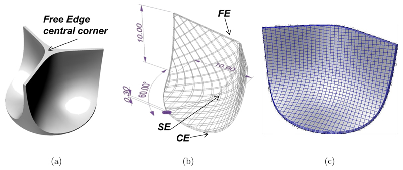
CAD modeling was used to draw the PHV leaflet shape (Fig. 1(a)) to fit into the host anatomy with appropriate coaptation of the leaflets when the valve is closed to avoid backward flow. The design of a biomorphic PHV depends on the shape of three critical regions (Fig. 1(b)): Commissural Edge (CE), Free-Edge (FE) and leaflet curvature Shape Edge (SE). NURBS-based CAD modeling was chosen to get flexibility in the description of the valve geometry. An automatic procedure was developed using the commercial scripting tool RhinoSCRIPT (Rhinoceros, McNeel & Assoc.): After setting the PHV class (i.e., circular, symmetric, trileaflet), the anatomical fitting parameters (i.e., 20mm in diameter and 10mm in height) and a constant leaflet thickness, the procedure calculates the NURBS parameterization of CE and FE. An automatic non rigid registration procedure provides the NURBS surfaces which best fit the boundary curves CE and FE, keeping the thickness constraint (Fig. 1(b)). A finite element model (Abaqus®, SIMULIA, Dessault Systèmes) was developed to analyze the mechanical behavior of the valve as a function of the leaflet thickness (t24 = 0.24 mm, t35 = 0.35 mm and t60 = 0.60 mm). Each 3D solid model was discretized with about 3000 linear hexahedral elements (Fig. 1(c)).
Fig. 1.
PHV CAD model: (a) Sketch of a trileaflet HV; (b) automatic drawing procedure to model the edges (FE = free edge, CE = commissure Edge, SE = shape edge); (c) 3D solid model of the leaflet.
A single leaflet was considered, due to the valve geometry periodicity (120°). The mechanical effect of the omitted leaflets was accounted by means of kinematic constraints blocking displacement beyond the plane of symmetry of the PHV.
All the displacements at the CE were avoided to simulate the presence of the valve stent. Uniform static pressure (24 kPa) was applied over the concave face of the leaflet to simulate the maximum transvalvular pressure gradient (diastolic load). The polymer mechanical behavior was modeled by a newly formulated hyperelastic anisotropic constitutive law6,7; the strain energy function consists of the sum of three terms: a term referring to a volumetric change of the material (ψvol), the contribution of an isotropic matrix (ψiso), and a term which takes into account the presence of stiff polymeric micro-domains (ψaniso) oriented along the circumferential direction. This orientation is specified by the unit vector a0, which appears in the definition of I4:
| (1) |
Volumetric contribution
| (2) |
Isotropic contribution (Mooney-Rivlin)
| (3) |
| (4) |
where K is the bulk modulus (penalty coefficient of volumetric changes), c1 and c2 are constants related to the shear modulus of the material. The model parameters K, c1, c2 and k4 were fitted to experimental data.5
2.2. Prototype in vitro testing
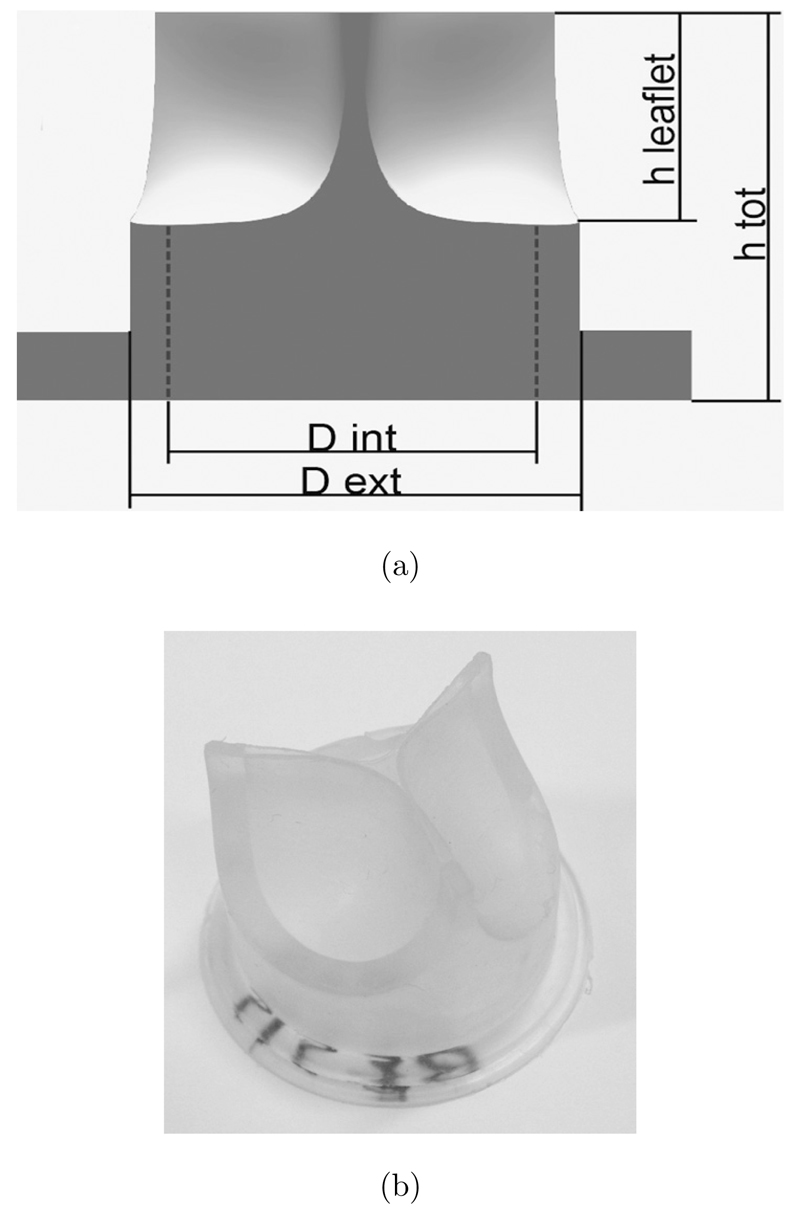
Based on the CAD design and finite element model outcomes, 8 PHV prototypes (Fig. 2) were manufactured by compression molding from poly(styrene-isoprene/butadiene-styrene), with 19% polystyrene weight fraction.
Fig. 2.
PHV prototype design: (a) Sketch of the PHV: hleaflet = 10.8 mm; htot = 21 mm; Dint = 22 mm; Dext = 28 mm; (b) prototype of a PHV obtained by compression molding.
In vitro tests were performed under both continuous and pulsatile flow on a test bench8,9 as recommended by ISO 5840 Standard,10 using distilled water at 25°C.
Steady tests were performed at flow rates from 0 to 10 L/min (steps 0.5 L/min). Regurgitation tests were run applying a backpressure in the range of 28–128mmHg (steps 5mmHg). A pulse duplicator was specifically designed to perform pulsatile flow tests replicating the peripheral compliance and the resistances of the cardiovascular system by a resistance-compliance-resistance (RCR) analogue.8,9 Each PHV was tested under three different frequencies (45 bpm, 70 bpm, 120 bpm), three backpressures (80mmHg, 120mmHg, 160 mmHg) and four mean flow rates (2 L/min, 3.5 L/min, 5 L/min and 7 L/min), as required by the ISO 5840 Standard for at least 15 cycles.
3. Results and Discussion
3.1. Finite element model results
Finite element analyses were performed on t24, t35 and t60 models to calculate the stress distribution within the leaflet (Fig. 3). Due to the leaflet symmetry, all models show a symmetrical distribution of stress. Under the diastolic load, all the leaflet geometries assure appropriate coaptation of the leaflets, while t24 shows a significant stress increase near the junction between FE and commissural region. Model t60 presents no significant stress peaks but a reduced coaptation area; moreover, the thickness of the leaflet may limit opening and closing of the PHV. Model t35 seems to be the best compromise amongst the analyzed geometries.
Fig. 3.
Computational outcomes as a function of the leaflet thickness: (a) Coaptation area; (b) Von Mises stress [MPa].
3.2. In vitro tests results
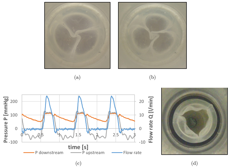
Mean transvalvular pressure drop (8.36 ± 1.33 mmHg) and mean regurgitation (175.3 ± 19 mL/min) were recorded during continuous flow and static regurgitation tests.
Figures 4(a) and 4(b) shows minimal leakage area formed during static regurgitation tests.
Fig. 4.
In vitro tests results: (a) and (b) PHVs during static regurgitation tests at backpressure 28 mmHg (a) and 128 mmHg (b); (c) Pressure and flow courses of the PHV during pulsatile tests; (d) maximum opening of the PHV.
During pulsatile flow tests mean (12.20 ± 1.41 mmHg) and maximum (30.09 ± 4.7 mmHg) systolic pressure differences were recorded.
Regurgitation (7.13% ± 1.33) and EOA (1.445 ± 0.08 cm2) of all the PHVs meet the requirements defined by ISO 5840 Standard (i.e., regurgitation < 10% of the stroke volume and EOA > 1 cm2 for a 23 mm valve).
4. Conclusion
The computational model implemented in this study can be used as a tool for the optimization of the design of new PHVs: The automatic parametric CAD procedure allows a wide variety of leaflet designs to be investigated and the standardized finite element model procedure gives information about the mechanical response of the device before prototyping. In this study the model was used to define the optimal leaflet thickness (t = 0.35 mm), able to maximize the coaptation area while reducing the stress on the leaflet. With the same approach, the model can be used to investigate the influence of other geometrical parameters (e.g., leaflet height, curvature, commissure shape, etc.) and of the material properties. Block copolymers based on styrene are promising materials for PHV prostheses thanks to their features of mechanical stability, biocompatibility and the possibility to achieve tailored anisotropy. The arrangement of the micro-domains can be optimized to enhance the valve durability under physiological stress conditions.
The experimental hydrodynamic evaluation of PHV prototypes showed all 8 PHVs meet the minimum requirements specified by the standard10 in terms of both regurgitation and EOA. The tests proved that the performance of these new PHV is comparable with the performances of some bi-leaflet mechanical prostheses currently used in clinics, having a comparable tissue annulus diameter.11 However, design improvements in terms of polymer cylindrical domain orientation and molding techniques are ongoing to further minimize regurgitation and maximize EOA. In vitro fatigue tests are also ongoing to prove PHV long term reliability before performing in vivo animal trials, necessary to definitely assess the PHV suitability for clinical applications.
Acknowledgments
This work was funded by the British Heart Foundation (New Horizons NH/11/4/29059).
Contributor Information
Anna Pandolfi, Department of Civil and Environmental Engineering Politecnico di Milano Piazza Leonardo da Vinci 32, 20133 Milan, Italy, anna.pandolfi@polimi.it.
Maria Laura Costantino, Department of Chemistry Materials and Chemical Engineering “Giulio Natta” Politecnico di Milano Piazza Leonardo da Vinci 32, 20133 Milan, Italy marialaura.costantino@polimi.it.
References
- 1.Edmunds LH, Jr, Mckinlay S, Anderson JM, Callahan TH, Chesebro JH, Geiser EA, et al. Directions for improvement of substitute heart valves: National Heart, Lung, and Blood Institute’s Working Group report on heart valves. J Biomed Mater Res. 1997;38:263–266. doi: 10.1002/(sici)1097-4636(199723)38:3<263::aid-jbm11>3.0.co;2-c. [DOI] [PubMed] [Google Scholar]
- 2.Ghanbari H, Viatge H, Kidane AG, Burriesci G, Tavakoli M, Seifalian AM. Polymeric heart valves: New materials, emerging hopes. Trends Biotechnol. 2009;27(6):359–367. doi: 10.1016/j.tibtech.2009.03.002. [DOI] [PubMed] [Google Scholar]
- 3.Stasiak J, Squires AM, Castelletto V, Hamley IW, Moggridge GD. Effect of Stretching on the Structure of Cylinder- and Sphere-Forming Styrene-Isoprene-Styrene Block Copolymers. Macromolecules. 2009;42:5256–5265. [Google Scholar]
- 4.Stasiak J, Brubert J, Serrani M, Nair S, De Gaetano F, Costantino ML, Moggridge GD. A bio-inspired microstructure induced by slow injection moulding of cylindrical block copolymers. Soft Matter. 2014;10(32):6077–6086. doi: 10.1039/c4sm00884g. [DOI] [PMC free article] [PubMed] [Google Scholar]
- 5.Stasiak J, Moggridge GD, Zaffora A, Pandolfi A, Costantino ML. Engineering orientation in block copolymers for application to prosthetic heart valves. Functional Material Letters. 2010;3(4):249–252. [Google Scholar]
- 6.Zaffora A. Computational method for the design of innovative materials for heart valve prostheses. PhD Dissertation; Politecnico di Milano, Milan, Italy: 2011. [Google Scholar]
- 7.Pandolfi A, Vasta M. Fiber distributed hyperelastic modeling of biological tissues. Mechanics of Materials. 2012;44:151–162. [Google Scholar]
- 8.Lanzarone E, Vismara R, Fiore GB. A new pulsatile volumetric device with biomorphic valves for the in vitro study of the cardiovascular system. Artif Organs. 2009;33(12):1048–1062. doi: 10.1111/j.1525-1594.2009.00812.x. [DOI] [PubMed] [Google Scholar]
- 9.De Gaetano F, Serrani M, Stasiak J, Brubert J, Bagnoli P, Moggridge GD, Costantino ML. Hydrodynamic assessment of new polymeric heart valves under continuous and pulsatile flow. Int J Artif Organs. 2014;37(8):622. doi: 10.5301/ijao.5000452. [DOI] [PMC free article] [PubMed] [Google Scholar]
- 10.International Standard ISO 5840. Cardiovascular implants — Cardiac valve prostheses. Fourth edition 2005-03-01. — Implants cardiovascular (References number ISO 5840:2005(E))
- 11.Bottio T, Caprili L, Casarotto D, Gerosa G. Small aortic annulus: The hydrodynamic performance of 5 commercially available bileaflet mechanical valves. J Thorac Cardiovasc Surg. 2004;128(3):457–462. doi: 10.1016/j.jtcvs.2004.03.021. [DOI] [PubMed] [Google Scholar]


