Abstract
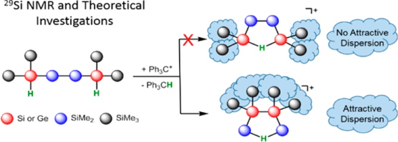
The installation of structural complex oligosilanes from linear starting materials by Lewis acid induced skeletal rearrangement reactions was studied under stable ion conditions. The produced cations were fully characterized by multinuclear NMR spectroscopy at low temperature, and the reaction course was studied by substitution experiments. The results of density functional theory calculations indicate the decisive role of attractive dispersion forces between neighboring trimethylsilyl groups for product formation in these rearrangement reactions. These attractive dispersion interactions control the course of Wagner–Meerwein rearrangements in oligosilanes, in contrast to the classical rearrangement in hydrocarbon systems, which are dominated by electronic substituent effects such as resonance and hyperconjugation.
Introduction
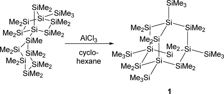
A major impetus for the development of microelectronics is the constant quest for ever smaller integrated circuits defined by Moore’s law.1 A useful bottom-up approach to semiconductor devices could be the synthesis of small silicon clusters, molecular entities of defined structures that resemble parts of crystalline or amorphous silicon. Silicon clusters of diverse structural complexity with intriguing electronic and bonding properties have been synthesized by reductive oligomerization of polyhalosilanes2−20 or disproportionation reactions of Si2Cl6.21 A different synthetic approach to silicon cluster structures is the rearrangement of linear poly- or oligosilanes catalyzed by Lewis acids.22 Pioneering work of Kumada’s and West’s groups showed that by using AlCl3 as the catalyst, linear oligosilanes can be transformed to structures of higher complexity such as branched or cyclic systems.23−27 Recently, we have been able to document the activity of carbocations, such as the trityl cation, in these catalytic rearrangement reactions.28 Furthermore, the use of a trityl cation paired with a weakly coordinating anion in stoichiometric amounts allowed the detection of oligosilanylsilyl cations under carefully controlled reaction conditions.28,29 The most prominent example for this type of Lewis acid catalyzed sila-Wagner–Meerwein rearrangement is the synthesis of persilaadamantane 1 from a bicyclic precursor that was reported recently by two of us (Scheme 1).30 During this transformation, the complexity of the bicyclic compound increases significantly by increasing the number of tetrasila-substituted silicon atoms. While the formation of the persilaadamantane is certainly a multiple-step reaction, the key for controlling this type of rearrangement is a profound understanding of the generation of branched oligosilanes from linear starting materials, which increases the number of tetrasila-substituted silicon atoms. Scheme 2 provides an example for this type of reaction in which the linear oligosilane 2 is transformed initially into its branched isomers 3 and 4.25,31 We have studied the reaction shown in Scheme 2 by ionizing close derivatives of oligosilane 2 at low temperature and characterized important cationic intermediates, which has allowed the formulation of a detailed mechanism for this reaction. In addition, the accompanying computational studies have provided clear indications that favorable attractive London dispersion forces32 in these intermediates drive these types of skeletal rearrangement reactions in the direction of branched products such as 4.
Scheme 1. Synthesis of Persilaadamantane 1(30).
Scheme 2. Lewis Acid Catalyzed Rearrangement of Linear Oligosilane 2 To Give Branched Oligosilanes 3 and 4(25,31).
Results and Discussion
The starting point of our experimental investigation was the ionization of 2,5-dihydridohexasilane 5(33) as a mimic for oligosilane 2. The use of the dihydrido compound 5 in our study instead of the dimethyl compound 2 has two advantages: (i) the position for the cation formation is clearly defined by the position of the accessible Si–H bonds, and (ii) the second Si–H linkage serves as an autoscavenge reagent, stabilizing the incipient cation by formation of a Si–H–Si bond. The increased stability of the so-formed bis-silylhydronium ion suggests that its NMR detection and characterization are possible without affecting the topology of the originally formed silyl cation. Using this methodology, we are able to identify otherwise only transient cationic species in rearrangement reactions of oligosilanes.29
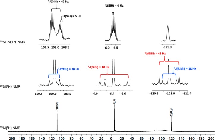
From the reaction of dihydrido-oligosilane 5 with trityl borate, [Ph3C][B(C6F5)4], we thus expected the formation of bis-silylhydronium ion 7 as the self-trapping product of the logically first-formed cation 6 (Scheme 3). The reaction was conducted in chlorobenzene at T = −30 °C and produced almost selectively a polysilanyl cation with a highly symmetric structure. The formed cation is characterized by only three 29Si NMR resonances in the 29Si{1H} NMR spectrum at δ29Si = 108.9, −6.4, and −120.9 (Scheme 3 and Figure 1). In the proton-coupled 29Si INEPT NMR spectrum, the high-field signal at δ29Si = −120.9 appears in a spectral region that is typical for tetrasila-substituted silicon atoms34 and is only broadened by unresolved couplings to distant hydrogen atoms. The resonance at δ29Si = −6.4 is a multiplet in the 29Si INEPT spectrum. Its chemical shift region suggests an assignment as a SiMe3 group. The low-field signal at δ29Si = 108.9 reveals a doublet of septets pattern with coupling constants of 1J(SiH) = 43 Hz and 3J(SiH) = 5 Hz. This chemical shift and the small size of the 1J(SiH) coupling constant are characteristic of cationic Si–H–Si groups.29,35−45 In the 1H29Si HMQC spectrum, this signal correlates with a broad singlet in the 1H NMR spectrum at δ1H = 2.15. The analysis of 29Si satellites for this signal also reveals a 1J(SiH) coupling of 43 Hz. Interestingly, the low-field 29Si resonance also shows a correlation to a singlet in the 1H NMR spectrum, which we assigned to a SiMe2 group based on the relative intensity in the 1H NMR spectrum. Supported by additional one- and two-dimensional NMR studies, we assigned the structure of bis-silylhydronium ion 8 to the produced cation (see Figure 2, Scheme 3, and Supporting Information). In particular, the analysis of the 1J(SiSi) coupling pattern was highly instructive, which established the connectivity of the silicon atoms and secured our structural assignment (see Figures 1 and 2). Cation 8 was transformed into the branched dihydrido compound 9 by reaction with Na[Et3BH] at −30 °C (Scheme 3). Compound 9 was identified by its 29Si NMR chemical shifts (δ29Si = −8.8 (SiMe3), −30.2 (SiHMe2), and −132.9 (SiSi4)) and by comparison with literature data.46
Scheme 3. Ionization of Dihydrido-oligosilane 5 To Give Hydronium Ion 8 and Its Trapping Reaction To Give Oligosilane 9.
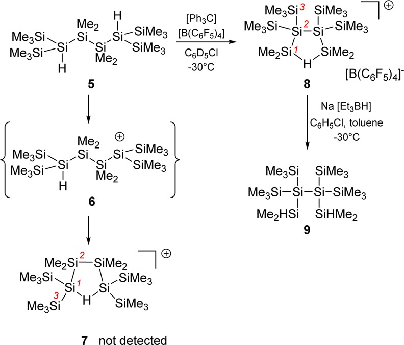
Figure 1.
29Si{1H} NMR spectrum (99 MHz, C6D5Cl, T = −30 °C) of the reaction mixture after hydride abstraction from oligosilane 5. Insets are taken from the 29Si INEPT (top trace) and the 29Si{1H} NMR (bottom trace) spectrum (*unidentified compound).
Figure 2.

Structure elucidation of cation 8 based on the analysis of detected 1J couplings (left) and 1H/29Si correlations based on HMQC and HMBC spectra.
Finally, our structural assignment for the formed cation was corroborated by the good agreement between the experimental 29Si NMR parameters and those computed by quantum mechanical calculations (see Table 1).47,48 The largest deviation was found for the tetrasila-substituted silicon atoms (calculated δ29Si = −124.8 vs experimental δ29Si = −120.9). Noteworthy is the fine accordance between calculated and experimental data for the central Me2Si–H–SiMe2 unit (calculated δ29Si = 105.9, 1J(SiH) = 40 Hz vs experimental δ29Si = 108.9, 1J(SiH) = 43 Hz). In addition, the results of calculations for cation 7 deviate significantly from those found in the experiment, suggesting that cation 7 is not present in the reaction mixture. The immediate and selective formation of cation 8 was surprising to us. It showed, however, the pronounced tendency of the formed polysilanyl cations to favor structural arrangements with tetrasila-substituted silicon atoms.
Table 1. Experimental and Calculated (in Italics) NMR Parameters of Cations 7, 8, 11, and 12a.
Next, we turned our attention to the actual reaction mechanism for the formation of cation 8. Substitution of the trisila-substituted silicon atoms by germanium atoms in hexasilane 5 is not expected to change the reactivity significantly, but it allows following the reaction course (Scheme 4). Based on the experience with oligosilane 5, we expected that hydride transfer from the 2,4-digermahexasilane 10 should result either in formation of bis-silylhydronium ion 11 or in the generation of bis-germylhydronium ion 12. The first cation is produced by complete skeletal rearrangement with disruption of the central Si–Si bond in 10 and reorientation of the fragments.
Scheme 4. Ionization of Digermaoligosilane 10 To Give Bis-silylhydronium Ion 11.
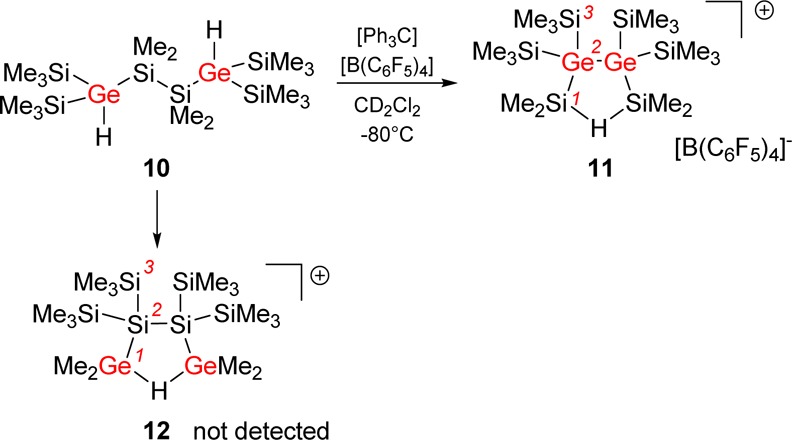
In contrast, in cation 12, the central backbone of germasilane 10 is conserved and the reorientation of the silyl and methyl groups must have taken place by successive 1,2-shifts. The reaction of digermahexasilane 10 with trityl cation results in the formation a thermally unstable cation. Even at reaction temperatures as low as −40 °C, we noted severe decomposition of the formed product (see Supporting Information). Only the use of dichloromethane as solvent and reaction temperatures as low as −95 °C allowed the clean and selective formation of a new cation, which was identified by 29Si NMR spectroscopy at −80 °C.
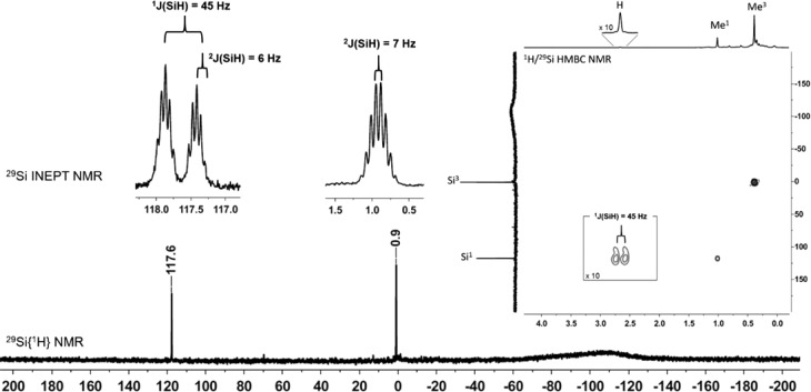
Only two 29Si NMR signals at δ29Si = 117.6 and δ29Si = 0.9 suggested a highly symmetric structure for the produced cation. Decisive for the structural assignment was the low-field signal with a 29Si NMR chemical shift, which is characteristic for a cationic Si–H–Si unit (δ29Si = 117.6) and which is a doublet in the 29Si INEPT spectrum with a Si–H coupling constant of 1J(SiH) = 45 Hz.35 In addition, this 29Si resonance shows cross-peaks to 1H NMR signals at δ1H = 2.66 and δ1H = 1.02 in the 1H/29Si HMBC NMR spectrum (Figure 3). The broad 1H NMR signal shows characteristic 29Si satellites of 1J(SiH) = 45 Hz. This clearly indicates that the formed species is cation 11. The good agreement between computed NMR chemical shifts and experimental data further substantiated the assignment of the signals (see Table 1).
Figure 3.
29Si{1H} NMR spectrum (99 MHz, CD2Cl2, T = −80 °C) of the reaction mixture after hydride abstraction from digermaoligosilane 10. Insets are taken from the 29Si INEPT spectrum and the 1H/29Si HMBC NMR spectrum.
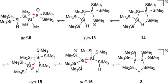
Based on these experimental results, we suggest the following mechanism for the formation of the characterized cation 8 and likewise for its digerma analogue 11 (Scheme 5). The logical starting compound for the reaction sequence is cation anti-6, which undergoes a 1,2-silyl shift with disruption of the central Si–Si bond to give the open cation 13 in its syn-conformation. The subsequent formation of the hydrogen-bridged cation 14 allows for a facile 1,4-hydride shift to give the open cation syn-15. A second 1,2-silyl shift followed by rotation around the central Si–Si bond in anti-16 results in the formation of the cyclic bis-silylated hydronium ion 8.
Scheme 5. Suggested Reaction Mechanism for the Formation of Cation 8.
The results of quantum mechanical computations47,48 provided (i) important insights with respect to the thermodynamic driving force for the formation of the branched cations 8 and 11 and (ii) the basis for a deeper mechanistic discussion of the reaction sequence shown in Scheme 5. In the following discussion, we will concentrate on the rearrangements in the oligosilanyl system. The results for the digerma analogue are quite similar with respect to the relative energies of the isomers and their calculated structures and are given in the Supporting Information. The close similarities between the persila- and the digermasila systems indicate that the perturbation induced by the replacement of silicon atoms by germanium atoms is not likely to change our conclusions. As expected, the results of density functional theory (DFT) calculations at the M06-2X/6-311+G(d,p) level for the gas-phase indicate a significant stabilization of all investigated polysilanyl cations by 54–62 kJ mol–1 due to the formation of Si–H–Si linkages (6/7, 54 kJ mol–1; 13/14, 62 kJ mol–1; 16/8, 58 kJ mol–1).
The most stable hydrogen-bridged cation, the branched cation 8, is more stable by 16 kJ mol–1 than the intermediate cation 14 and more stable by 30 kJ mol–1 than cation 7, and it is the most stable cation that we located on the potential energy surface (PES) (see Figure 4, blue). We found this result rather surprising because the quantitative evaluation of substituent effects on the stability of cations having Si–H–Si units indicated that substitution with four trimethylsilyl groups at the two silicon atoms (α-substitution, as in cation 7) stabilizes this type of cation by 37 kJ mol–1 compared to tetramethyl substitution, as detailed in the Supporting Information.48 Substitution with four trimethylsilyl groups in the β-position to the Si–H–Si (as in cation 8) is less favorable and stabilizes only by 24 kJ mol–1. Consequently, comparison of the different substituent effects of the trimethylsilyl groups in cations 7 and 8 suggests that cation 7 is more stable than the branched cation 8. This fact raises the question about the driving force for the selective formation of cation 8 in the experiment. Furthermore, the accumulation of four trimethylsilyl groups at the central Si–Si unit in cation 8 seemed to us to be a rather unfavorable situation for steric reasons. On the contrary, attractive dispersion forces between the vicinal trimethylsilyl groups in cation 8 could stabilize this cation compared to its isomers 7 and 14.32,49−51 The decisive role of attractive dispersion forces between large, polarizable silyl groups for the formation of tetrylene dimers was demonstrated recently by our groups50 and by Nagase and Power.51 In order to quantify the relative stabilization of cations 7, 8, and 14 by attractive dispersion forces, we optimized their molecular structures at the B3LYP/6-311+G(d,p) level. This DFT method practically neglects dispersion interactions.32 These results were compared with those obtained using the same functional but including Grimme’s D3 function, which adds dispersion corrections to the original B3LYP functional.52,53 Interestingly, the B3LYP calculations predict cation 14, which is putatively the sterically least congested one, to be the most stable compound in this series (see Figure 4, red). The outcome of the B3LYP/D3 calculations alters the relative order of stability between cation 14 and the branched cation 8 (see Figure 4, black). In addition, we note that the relative stability order for the three cations is the same at B3LYP/D3 as at the M06-2X level (see Figure 4, blue). Both methods predict the branched cation 8 to be the most stable one, which is in qualitative agreement with the exclusive NMR detection of cation 8 in the experiment. The fact that only DFT methods, which explicitly take dispersion energy contributions into account, are able to confirm the experimentally determined relative stability order hints at the importance of dispersion energy contributions in this system. The comparison between the three isomeric structures suggests that London dispersion forces are maximized in cation 8 and overrule unfavorable substituent effects (compared to cation 7) and disadvantageous steric repulsion (relative to cation 14). As a consequence, the attractive dispersion forces between the vicinal trimethylsilyl substituents in the branched cation 8 provide the thermodynamic driving force for its exclusive formation in the experiment. There is a clear relation also to the rearrangement reaction shown in Scheme 2. In the framework of our model chemistry, which replaces selected methyl groups with hydrogen atoms, cations 7, 8, and 14 are placeholders for the linear starting material 2 and the branched oligosilanes 3 and 4. Therefore, the determined relative stability order in the cations 7, 8, and 14 clearly reflects the observed rearrangement chemistry shown in Scheme 2. This fact suggests that dispersion energy contributions strongly influence the relative stability order of the intermediate cations of this rearrangement and are at least important components to its thermodynamic driving force. Nevertheless, the selective and exclusive formation of cation 8 with no indications for the presence of cation 14 contrasts the experimental finding for the actual rearrangement reaction (Scheme 2), with both oligosilanes 3 and 4 formed initially in equal amounts.31 In an attempt to tackle this aspect, we started a detailed computational investigation of the PES connecting the isomeric cations 7, 8, and 14. The result of these calculations revealed a delicate balance between inter- and intramolecular stabilization of the silyl cation center. As shown above, the formation of Si–H–Si hydrogen bridges stabilizes the cations 7, 8, and 14 significantly. For these cations, direct coordination of the positively charged silicon atom to solvent molecules is not of chemical significance even in solution. The calculated dissociation energies ΔEdiss for the complexes of the three hydrogen-bridged cations with chlorobenzene (PhCl) are small (ΔEdiss = 39 kJ mol–1 (8), 43 kJ mol–1 (14a, coordination via the SiMe2 group) and 47 kJ mol–1 (14b, coordination via the Si(SiMe3)2 group), and 44 kJ mol–1 (7)).54 In all three cases, the main structural features of the hydrogen-bridged cations are conserved also in the PhCl complex. This is shown, for example, by the close agreement between the calculated NMR parameter for the gas-phase structure of cation 8 and for the complex 8(PhCl) (see Table 1 and Supporting Information for a structural comparison). In addition, entropy effects favor the dissociation of these aggregates into cation and solvent molecule, and their Gibbs energy of dissociation, ΔGdiss(298), is calculated to be negative (ΔGdiss(298) = −14 kJ mol–1 (8), −9 and −10 kJ mol–1 (14), and −11 kJ mol–1 (7)), which negates their chemical significance.55
Figure 4.
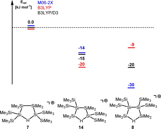
Relative energies of isomers 7, 8, and 14, calculated using different density functionals. Values obtained at B3LYP (red) do not include dispersion interactions. B3LYP/D3 (black) correct the B3LYP values for dispersion interaction using Grimme’s D3 function. The M06-2X functional includes dispersion interaction (blue). All calculations use the 6-311+G(d,p) basis set.
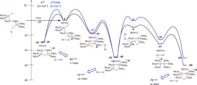
The situation is different, however, for their open isomers with tricoordinated positively charged silicon atoms. Structure optimizations for cations such as anti-6 resulted either in rearrangements (e.g., to cation syn-13) or in cations which show clear structural indications for stabilization by remote methyl or silyl groups (see Supporting Information for details and examples). The interaction energies for the latter stabilization modes are significantly smaller than that computed for the formation of Si–H–Si bridges. Although these calculated structures are important for gas-phase investigations, in solution, intermolecular interaction with solvent molecules represses the intramolecular stabilization. As a consequence, for these non-hydrogen-bridged cations, explicit coordination to solvent molecules has to be taken into account. Therefore, we determined the relative energy of the intermediates for the proposed reaction pathway shown in Scheme 5 in the form of their PhCl complexes and used the polarized continuum model56 to include the general effects of solvation (Figure 5).
Figure 5.
Approximate reaction coordinate for the formation of the hydrogen-bridged cation 8 starting from the complex between cation 6 and PhCl. The relative energies Erel (black) and the relative Gibbs energies Grel(298) at 298 K (blue) of the aggregates between cations and solvent are computed using the M06-2X/6-311+G(d,p) functional and are given relative to the energy of the complex 6(PhCl). The influence of the solvent was modeled by SCRF calculations using chlorobenzene as solvent. The barriers shown are drawn arbitrarily; see the Supporting Information for details. For cation 14, only complex 14b(PhCl) with the lowest energy is shown. Complex 14a(PhCl) (coordination via the SiMe2 group) is higher in energy by 5 kJ mol–1.
In an extended computational search for transition states connecting these cationic intermediates, we faced, on the one hand, a very flat potential energy surface on which no transition state relevant to the investigated chemical transformations could be located. All barriers found belonged to rotations of methyl or silyl groups. On the other hand, on a PES on which topology is dominated by weak rotation modes, no other large barriers are to be expected. This allows an approximate discussion of the PES based on the different energies of the intermediates of this reaction sequence. The computed reaction coordinate shown in Figure 5 reveals an energy difference of about 30–40 kJ mol–1 between the more stable hydrogen-bridged cations 7, 8, and 14 and their open isomers 6, 13, 15, and 16 (all in the form of their PhCl complexes). The least stable isomer in this series is 6(PhCl), which is higher in energy by 60 kJ mol–1 compared to the final product, the hydrogen-bridged cation 8. This relative small energy difference suggests that even at temperatures as low as −30 °C (the temperature of the experiment) the thermodynamic equilibrium between the hydrogen-bridged cations via their open isomers is fully established and explains the selective formation of the most stable cation, the branched hydrogen-bridged cation 8. In order to put the results for our model system into relation to the preparative important rearrangement chemistry of Scheme 2, it is interesting to note that the energy difference between cation solvent complexes 14(PhCl) and 8(PhCl) is relatively small (ΔE = 11 kJ mol–1 in favor of cation 8). Thermal and entropy effects favor the dissociation of both PhCl complexes, and the Gibbs energy difference at 298 K, ΔG(298), between the cation 14 and 8 decreases to 6 kJ mol–1.57 Against the background that cation 14 and 8 are placeholders for the oligosilanes 3 and 4, it is reasonable to assume that at higher temperatures or different solvents a mixture of products is obtained.58
Conclusions
We investigated the Lewis acid induced rearrangement reaction of linear oligosilanes to give new structures of higher complexity. We used dihydrogen-substituted starting silanes for our stoichiometric model reactions, which allow the targeted formation of cationic intermediates by cleavage of one Si–H bond and their stabilization by formation of Si–H–Si bonds with the second Si–H bond. The cationic products of the rearrangement reaction were characterized at low temperatures by multinuclear NMR spectroscopy. Substitution experiments identified the cleavage of the central Si–Si bond of the oligosilane backbone as the key step for the production of an oligosilane structure with a higher number of tetrasila-substituted silicon atoms. According to accompanying DFT calculations, a major contributors to the thermodynamic driving force for this reaction are attractive dispersion forces between the polarizable trimethylsilyl groups, which are maximized in the detected products. The course of Wagner–Meerwein rearrangements in carbon chemistry is usually discussed in terms of carbocation stabilities that are defined by substituent effects, such as resonance and hyperconjugation. Due to the increased size of the silicon atoms, these effects are not as pronounced in polysilanyl cations as in carbocations. The results of our combined experimental/computational investigation indicate instead that attractive dispersion forces between large polarizable silyl substituents play a dominant role in skeletal rearrangement reactions of oligosilanes and determine the configuration of the products.
Acknowledgments
This work was supported by the ERA-chemistry program (DFG Mu1440/8-1, FWF-I00669) and by the Carl von Ossietzky University Oldenburg. The simulations were performed at the HPC Cluster HERO (High End Computing Resource Oldenburg), located at the University of Oldenburg (Germany), and funded by the DFG through its Major Research Instrumentation Program (INST 184/108-1 FUGG) and the Ministry of Science and Culture (MWK) of the Lower Saxony State.
Supporting Information Available
The Supporting Information is available free of charge on the ACS Publications website at DOI: 10.1021/jacs.6b03560.
Computed structures of Figure 4 (XYZ)
Computed structures of Figure 5 (XYZ)
Computed structures of Figure S15 (XYZ)
Computed structures of Figure S16 (XYZ)
Computed structures of Figure S17 (XYZ)
Computed structures of Figure S18 (XYZ)
Experimental and theoretical characterization, including preparation of all compounds of interest and computational details (PDF)
Author Present Address
⊥ (Lena Albers) School of Chemistry, University of Edinburgh, Edinburgh EH9 3FJ, UK.
The authors declare no competing financial interest.
Supplementary Material
References
- Moore G. E. Electronics 1965, 38, 4. [Google Scholar]
- Sekiguchi A.; Nagase S. In The Chemistry of Organic Silicon Compounds; Rappoport Z., Apeloig Y., Eds.; Wiley: Chichester, 1998; Vol. 2, p 119. [Google Scholar]
- Hengge E.; Stüger H. In The Chemistry of Organic Silicon Compounds; Rappoport Z., Apeloig Y., Eds.; Wiley: Chichester, 1998; Vol. 2, p 2177. [Google Scholar]
- Wiberg N.; Finger C. M. M.; Polborn K. Angew. Chem., Int. Ed. Engl. 1993, 32, 1054. 10.1002/anie.199310541. [DOI] [Google Scholar]
- Ichinohe M.; Toyoshima M.; Kinjo R.; Sekiguchi A. J. Am. Chem. Soc. 2003, 125, 13328. 10.1021/ja0305050. [DOI] [PubMed] [Google Scholar]
- Sekiguchi A.; Yatabe T.; Kabuto C.; Sakurai H. J. Am. Chem. Soc. 1993, 115, 5853. 10.1021/ja00066a075. [DOI] [Google Scholar]
- Abersfelder K.; Russell A.; Rzepa H. S.; White A. J. P.; Haycock P. R.; Scheschkewitz D. J. Am. Chem. Soc. 2012, 134, 16008. 10.1021/ja307344f. [DOI] [PubMed] [Google Scholar]
- Matsumoto H.; Higuchi K.; Hoshino Y.; Koike H.; Naoi Y.; Nagai Y. J. Chem. Soc., Chem. Commun. 1988, 1083. 10.1039/c39880001083. [DOI] [Google Scholar]
- Sekiguchi A.; Yatabe T.; Kamatani H.; Kabuto C.; Sakurai H. J. Am. Chem. Soc. 1992, 114, 6260. 10.1021/ja00041a063. [DOI] [Google Scholar]
- Matsumoto H.; Higuchi K.; Kyushin S.; Goto M. Angew. Chem., Int. Ed. Engl. 1992, 31, 1354. 10.1002/anie.199213541. [DOI] [Google Scholar]
- Nied D.; Köppe R.; Klopper W.; Schnöckel H.; Breher F. J. Am. Chem. Soc. 2010, 132, 10264. 10.1021/ja104810u. [DOI] [PubMed] [Google Scholar]
- Iwamoto T.; Tsushima D.; Kwon E.; Ishida S.; Isobe H. Angew. Chem., Int. Ed. 2012, 51, 2340. 10.1002/anie.201106422. [DOI] [PubMed] [Google Scholar]
- Fischer G.; Huch V.; Mayer P.; Vasisht S. K.; Veith M.; Wiberg N. Angew. Chem., Int. Ed. 2005, 44, 7884. 10.1002/anie.200501289. [DOI] [PubMed] [Google Scholar]
- Scheschkewitz D. Angew. Chem., Int. Ed. 2005, 44, 2954. 10.1002/anie.200462730. [DOI] [PubMed] [Google Scholar]
- Abersfelder K.; White A. J. P.; Berger R. J. F.; Rzepa H. S.; Scheschkewitz D. Angew. Chem., Int. Ed. 2011, 50, 7936. 10.1002/anie.201102623. [DOI] [PubMed] [Google Scholar]
- Abersfelder K.; White A. J. P.; Rzepa H. S.; Scheschkewitz D. Science 2010, 327, 564. 10.1126/science.1181771. [DOI] [PubMed] [Google Scholar]
- Suzuki K.; Matsuo T.; Hashizume D.; Fueno H.; Tanaka K.; Tamao K. Science 2011, 331, 1306. 10.1126/science.1199906. [DOI] [PubMed] [Google Scholar]
- Ishida S.; Otsuka K.; Toma Y.; Kyushin S. Angew. Chem., Int. Ed. 2013, 52, 2507. 10.1002/anie.201208506. [DOI] [PubMed] [Google Scholar]
- Tsurusaki A.; Koganezono M.; Otsuka K.; Ishida S.; Kyushin S. Chem. - Eur. J. 2014, 20, 9263. 10.1002/chem.201403375. [DOI] [PubMed] [Google Scholar]
- Tsurusaki A.; Iizuka C.; Otsuka K.; Kyushin S. J. Am. Chem. Soc. 2013, 135, 16340. 10.1021/ja409074m. [DOI] [PubMed] [Google Scholar]
- Tillmann J.; Wender J. H.; Bahr U.; Bolte M.; Lerner H. W.; Holthausen M. C.; Wagner M. Angew. Chem., Int. Ed. 2015, 54, 5429. 10.1002/anie.201412050. [DOI] [PubMed] [Google Scholar]
- Marschner C. In Science of Synthesis, Knowledge Updates 2013; Oestreich M., Ed.; Thieme Verlag: Stuttgart, 2013; Vol. 2, p 109. [Google Scholar]
- Ishikawa M.; Kumada M. J. Chem. Soc. D 1969, 567. 10.1039/c2969000567b. [DOI] [Google Scholar]
- Ishikawa M.; Kumada M. J. Chem. Soc. D 1970, 157. 10.1039/c2970000157a. [DOI] [Google Scholar]
- Ishikawa M.; Iyoda J.; Ikeda H.; Kotake K.; Hashimoto T.; Kumada M. J. Am. Chem. Soc. 1981, 103, 4845. 10.1021/ja00406a029. [DOI] [Google Scholar]
- Ishikawa M.; Watanabe M.; Iyoda J.; Ikeda H.; Kumada M. Organometallics 1982, 1, 317. 10.1021/om00062a015. [DOI] [Google Scholar]
- Blinka T. A.; West R. Organometallics 1986, 5, 128. 10.1021/om00132a023. [DOI] [Google Scholar]
- Albers L.; Meshgi M. A.; Baumgartner J.; Marschner C.; Müller T. Organometallics 2015, 34, 3756. 10.1021/acs.organomet.5b00431. [DOI] [PMC free article] [PubMed] [Google Scholar]
- Albers L.; Baumgartner J.; Marschner C.; Müller T. Chem. Eur. J. 2016, 10.1002/chem.20160116. [DOI] [PMC free article] [PubMed] [Google Scholar]
- Fischer J.; Baumgartner J.; Marschner C. Science 2005, 310, 825. 10.1126/science.1118981. [DOI] [PubMed] [Google Scholar]
- Wagner H.; Baumgartner J.; Marschner C.; Poelt P. Organometallics 2011, 30, 3939. 10.1021/om1011165. [DOI] [PMC free article] [PubMed] [Google Scholar]
- Wagner J. P.; Schreiner P. R. Angew. Chem., Int. Ed. 2015, 54, 12274. 10.1002/anie.201503476. [DOI] [PubMed] [Google Scholar]
- Kayser C.; Kickelbick G.; Marschner C. Angew. Chem., Int. Ed. 2002, 41, 989.. [DOI] [PubMed] [Google Scholar]
- Krempner C. Polymers 2012, 4, 408. 10.3390/polym4010408. [DOI] [Google Scholar]
- Müller T. In Structure and Bonding; Scheschkewitz D., Ed.; Springer: Berlin, 2014; Vol. 155, p 107. [Google Scholar]
- Müller T. Angew. Chem., Int. Ed. 2001, 40, 3033.. [DOI] [PubMed] [Google Scholar]
- Panisch R.; Bolte M.; Müller T. J. Am. Chem. Soc. 2006, 128, 9676. 10.1021/ja061800y. [DOI] [PubMed] [Google Scholar]
- Sekiguchi A.; Murakami Y.; Fukaya N.; Kabe Y. Chem. Lett. 2004, 33, 530. 10.1246/cl.2004.530. [DOI] [Google Scholar]
- Khalimon A. Y.; Lin Z. H.; Simionescu R.; Vyboishchikov S. F.; Nikonov G. I. Angew. Chem., Int. Ed. 2007, 46, 4530. 10.1002/anie.200604258. [DOI] [PubMed] [Google Scholar]
- Hoffmann S. P.; Kato T.; Tham F. S.; Reed C. A. Chem. Commun. 2006, 767. 10.1039/b511344j. [DOI] [PubMed] [Google Scholar]
- Nava M.; Reed C. A. Organometallics 2011, 30, 4798. 10.1021/om200636u. [DOI] [PMC free article] [PubMed] [Google Scholar]
- Connelly S. J.; Kaminsky W.; Heinekey D. M. Organometallics 2013, 32, 7478. 10.1021/om400970j. [DOI] [Google Scholar]
- Bolli C.; Derendorf J.; Jenne C.; Scherer H.; Sindlinger C. P.; Wegener B. Chem. - Eur. J. 2014, 20, 13783. 10.1002/chem.201403625. [DOI] [PubMed] [Google Scholar]
- Schäfer A.; Reißmann M.; Schäfer A.; Schmidtmann M.; Müller T. Chem. - Eur. J. 2014, 20, 9381. 10.1002/chem.201402874. [DOI] [PubMed] [Google Scholar]
- Kordts N.; Borner C.; Panisch R.; Saak W.; Müller T. Organometallics 2014, 33, 1492. 10.1021/om500154n. [DOI] [Google Scholar]
- Stella F.Synthesis, Rearrangement and Further Reactions of Organosilanes and Organostannes, Dissertation, Technical University Graz, 2016. [Google Scholar]
- All calculations were done using the Gaussian 09 program, version B1.
- For details, see the Supporting Information.
- Grimme S.; Schreiner P. R. Angew. Chem. 2011, 123, 12849. 10.1002/ange.201103615. [DOI] [PubMed] [Google Scholar]
- Arp H.; Baumgartner J.; Marschner C.; Zark P.; Müller T. J. Am. Chem. Soc. 2012, 134, 6409. 10.1021/ja300654t. [DOI] [PMC free article] [PubMed] [Google Scholar]
- Guo J.-D.; Liptrot D. J.; Nagase S.; Power P. P. Chem. Sci. 2015, 6, 6235. 10.1039/C5SC02707A. [DOI] [PMC free article] [PubMed] [Google Scholar]
- Grimme S.; Antony J.; Ehrlich S.; Krieg H. J. Chem. Phys. 2010, 132, 154104. 10.1063/1.3382344. [DOI] [PubMed] [Google Scholar]
- Grimme S. WIREs Comput. Mol. Sci. 2011, 1, 211. 10.1002/wcms.30. [DOI] [Google Scholar]
- ΔEdiss is calculated as the difference between the electronic energy of the optimized structure of the complex between the cation and PhCl and the sum of the electronic energies of the constituents (cation and PhCl).
- ΔGdiss(298) is calculated as the difference between the Gibbs energy of the optimized structure of the complex between the cation and PhCl at 298 K and the sum of the Gibbs energy of the constituents (cation and PhCl).
- Tomasi J.; Mennucci B.; Cammi R. Chem. Rev. 2005, 105, 2999. 10.1021/cr9904009. [DOI] [PubMed] [Google Scholar]
- The Gibbs energy difference between cation 8 and cation 14 of 6 kJ mol–1 suggests that at 243 K ≈5% of cation 14 could be present in equilibrium. The quality of the 29Si NMR spectra shown in Figure 1 does not allow, however, a clear assignment. A graphical comparison between calculated 29Si NMR spectra for cations 8 and 14 with the experimentally spectrum obtained for the reaction mixture is provided in the Suppporting Information (Figure S20).
- The Gibbs free energy differences between silanes 3 and 4 calculated at 298 K for the gas phase also do not differ significantly; that is, G298 values relative to silane 2 are calculated as follows: ΔG298(3) = −6 kJ mol–1 and ΔG298(4) = −24 kJ mol–1.
Associated Data
This section collects any data citations, data availability statements, or supplementary materials included in this article.


