Abstract
The characterization of the strength and fracture toughness of three common structural fibres, E-glass, AS4 carbon and Kevlar KM2, is presented in this work. The notched specimens were prepared by means of selective carving of individual fibres by means of the focused ion beam. A straight-fronted edge notch was introduced in a plane perpendicular to the fibre axis, with the relative notch depth being a0/D≈0.1 and the notch radius at the tip approximately 50 nm. The selection of the appropriate beam current during milling operations was performed to avoid to as much as possible any microstructural changes owing to ion impingement. Both notched and un-notched fibres were submitted to uniaxial tensile tests up to failure. The strength of the un-notched fibres was characterized in terms of the Weibull statistics, whereas the residual strength of the notched fibres was used to determine their apparent toughness. To this end, the stress intensity factor of a fronted edge crack was computed by means of the finite-element method for different crack lengths. The experimental results agreed with those reported in the literature for polyacrylonitrile-based carbon fibres obtained by using similar techniques. After mechanical testing, the fracture surface of the fibres was analysed to ascertain the failure mechanisms. It was found that AS4 carbon and E-glass fibres presented the lower toughness with fracture surfaces perpendicular to the fibre axis, emanating from the notch tip. The fractured region of Kevlar KM2 fibres extended along the fibre and showed large permanent deformation, which explains their higher degree of toughness when compared with carbon and glass fibres.
This article is part of the themed issue ‘Multiscale modelling of the structural integrity of composite materials’.
Keywords: fracture toughness, micromechanics, focused ion beam, structural fibres
1. Introduction
In the present state of technological development, small-diameter fibres such as aramid, carbon, glass or polyethylene, stand among the strongest man-made materials, with their application as reinforcement in composites particularly growing in lightweight applications owing to their excellent strength and stiffness-to-weight ratio. Fibres are normally embedded in a matrix, metal, ceramic or polymer, which maintains the orientation of the fibres according to specific design directions while providing them with effective protection in harsh environments. It is also well known that the properties of composites are essentially controlled by the corresponding properties of their constituents, including fibre/matrix interfaces and, obviously, their volume fraction and spatial distribution. The strength and stiffness of fibres are usually well characterized by the manufacturer by means of tensile tests carried out by direct straining of single fibres or strands containing thousands of such fibres. However, other important fibre mechanical properties, such as toughness, are less widely reported in published research owing to the enormous experimental difficulties associated with testing small-diameter fibres. Fibre toughness (or the critical defect dimension), in combination with the fibre/matrix interface, plays a crucial role in the ultimate failure stress and energy dissipation mechanisms in brittle unidirectional composites.
The most common methodology used in estimating the toughness of small-diameter fibres is based on direct observation of the fracture surfaces in post-mortem plain specimens. The fracture surface of the fibres often exhibits some remains, in the form of mirror, mist and hackle structures that allow the defect size to be determined, producing failure and consequently fracture toughness estimation. However, the methodology entails a large experimental scatter owing to the uncertainty in the determination of the exact defect size that caused the failure and the maximum stress attained during the experiments. The focused ion beam (FIB) opens revolutionary opportunities for testing materials at the microlevel by selective removing/carving material and generating complex geometries suitable for testing [1,2].
The basic concept of the aforementioned FIB is similar to scanning electron microscopy (SEM) but through the use of ions instead of electrons. A fine tungsten pin covered with liquid gallium (Ga) is used as an ion source from which Ga atoms are extracted and ionized via high voltage. Such Ga+ ions are then accelerated in the range of 0.5–50 keV and focused on the sample via electrostatic lenses. The interaction with the ion beam may be used both for imaging and for removing material through sputtering in selected locations, by the use of different detectors. Almost all the materials may be structured by FIB, ranging from soft matter (polymers) to ultra-hard material (diamond). However, when using FIB for surface structuring it should be kept in mind that this method can lead to ion implantation, thermal stresses and defect formation. This is the case in the direct measurement of fibre fracture toughness by direct tensile testing of notched fibres introduced by means of the FIB technique. This methodology permits precise monitoring of the geometry of the notch in terms of its depth and tip radius. The mode I apparent fracture toughness, KIC, is then inferred from the maximum strength of the notched fibres and geometry of the notch.
2. Material and experimental techniques
In this work, the strength and toughness of three common structural fibres used in composite manufacturing are obtained. AS4 (Hexcel (http://www.hexcel.com/resources/datasheets/carbon-fiber-data-sheets/as4.pdf)) is a high-strength carbon fibre manufactured from a polyacrylonitrile (PAN) precursor commonly used in prepregs and dry fabrics for aerospace structural applications. Alumino-borosilicate E-glass fibres (54%SiO2–15%Al2O3–12%CaO) are arguably the most common reinforcement for composites because of their low cost, high stiffness and strength, and high temperature resistance. Additionally, Kevlar KM2 (poly-paraphenylene terephthalamide branded by Dupont) aramid is an organic synthetic fibre of the aromatic polyamide family with high strength, modulus and toughness used to offer protection against fragment impacts.
Fibre strength and toughness were determined through dedicated tensile tests by using both un-notched and notched fibres. The fibres were first extracted carefully with mechanical tweezers from tows previously separated from the woven fabrics for the three cases analysed. Special care was taken to avoid damage while handling and mounting fibres for testing. The fibre ends were bonded with cyanoacrylate adhesive on cardboard with a 20 mm free-gauge length, with the embedded length being previously determined to eliminate sliding during the tests. A minimum of 15 fibres were dedicated to modulus and strength determination at room temperature in the case of un-notched fibres tests. The cardboard was directly connected to the mechanical grips of the fibre tensile tester (Favimat+, Textechno) and then submitted to uniaxial straining up to failure under stroke control at 1 mm min−1, leading to strain rates of the order of ≈10−3 s−1. The linear density of the fibres was determined by the fibre-tester system by using the frequency method according to the ASTM D1577 standard. The fibre is pre-stressed in this method to a given force in the range of 0.45–0.70 cN tex−1. Then, the natural frequencies are extracted to determine linear density and, subsequently, the cross-section area. These latter values were used to determine the individual strength and modulus of each fibre tested. All the tests were carried out at room temperature. Table 1 summarizes the linear density and average diameter of the population of fibres analysed.
Table 1.
Geometrical and mechanical properties of the fibres analysed.
| fibre type | linear density (tex) | diameter (mm) | elastic mod. (GPa) | Weibull strength σ0 (MPa) | Weibull modulus m (−) | average strength (MPa) |
|---|---|---|---|---|---|---|
| AS4 carbon | 0.84±0.03 | 7.8±0.2 | 229±14 | 3959 | 6.5 | 3687 |
| E-glass | 3.10±0.2 | 12.4±0.4 | 67±2 | 1951 | 4.1 | 1771 |
| Kevlar KM2 | 1.64±0.06 | 11.8±0.4 | 86±9 | 4095 | 6.5 | 3816 |
Those fibres used for fracture tests were first mounted on the same type of the aforementioned cardboard, although the edges in this case were carefully connected to a metal holder using a copper tape to provide the appropriate electrical paths during the fibre-milling operation. An FEI Helios NanoLabTM DualBeamTM 600i system equipped with an FIB was used to introduce the artificial notches in the fibres that act as a fracture imitator during the tensile test. Ga+ ions were accelerated in the FIB system by using 30 kV of potential, with the beam current being adjusted to 80 pA for the carbon fibres and 24 μA for the aramid and glass, respectively. The selection of the appropriate beam current was carried out to avoid microstructural changes owing to ion impingement during milling operations. Straight and sharp notches perpendicular to the fibre axis (a straight-fronted edge crack) were introduced in the three structural fibres analysed with a depth a0 to diameter D ratio of approximately a0/D≈0.1, figure 1a). The notch radius at the tip resulting from the FIB milling process was approximately ≈50 nm. The fibres were submitted to a uniaxial test up to failure by using the experimental set-up previously described for un-notched fibres. After the tensile tests, the fracture surface was observed by SEM to confirm the fracture location and check the quality of the notch, figure 1b). The surface texture validates the brittle fracture behaviour, and the fracture process starting from the crack tip induced by FIB milling.
Figure 1.
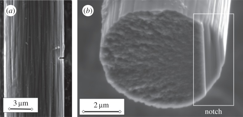
(a) Longitudinal view of an AS4 carbon fibre after the introduction of the straight notch perpendicular to the axis, (b) fracture surface of an AS4 carbon fibre after testing.
3. Results
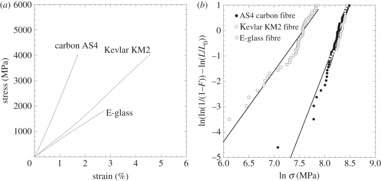
The response of un-notched fibres was linear and elastic up to failure (figure 2a). The elastic modulus in the fibre direction was determined from the slope of the stress–strain curve and the results, summarized in table 1, were consistent with data supplied by the fibre manufacturer (www.hexcel.com/resources/datasheets/carbon-fiber-data-sheets/as4.pdf) [3]. The strength was determined with the maximum load and the cross-section area measured through the frequency method of the fibre tester. Around 50 aramid, carbon and glass fibres were tested. The strength data of each group of fibres were arranged in ascending order and the failure probability (i−0.5)/N assigned to each individual strength, where i is the rank position and N the total number of fibres population. According to the Weibull statistics, the cumulative fracture probability function F is given by
 |
3.1 |
where L is the fibre length, L0 is an arbitrary reference length introduced for dimensional purposes, which was taken as equal to 20 mm in the present case, and σ0 and m stand, respectively, for the characteristic strength and the Weibull modulus of the fibre. They can be obtained through the least-squares fitting technique of the experimental results for the fibre cumulative fracture probability in figure 2b.
Figure 2.
(a) Stress–strain curve of un-notched fibres (AS4 carbon, E-glass, Kevlar KM2), (b) Weibull plots of the different fibres tested (AS4 carbon, E-glass, Kevlar KM2) with L0=20 mm guage length. Solid lines correspond to Weibull fitting according to equation (3.1).
The response of the notched fibres was also linear and elastic up to failure. The residual strength of the notched fibre was determined from the failure load and the corresponding area of the cross section of the fibre at the notch location measured after milling (table 2). A preliminary comparison of the effect of the notch on the strength of the fibre suggests increased defect sensitivity in carbon and glass fibres compared to the aramid fibres, which can be interpreted as lower material toughness of the carbon and glass fibres.
Table 2.
Residual strength and toughness of the fibres analysed.
| fibre type | a0/D | residual strength (MPa) | fracture energy (J m−2) | fibre toughness (MPa ⋅ m1/2) | Irwin plastic radius (μm) |
|---|---|---|---|---|---|
| AS4 carbon | 0.12±0.03 | 1256±307 | 52±2 | 2.12±0.45 | 0.105 |
| E-glass | 0.11±0.02 | 497±97 | 3.7±0.1 | 1.08±0.14 | 0.118 |
| Kevlar KM2 | 0.10±0.02 | 3194±369 | 1101±9 | 6.63±0.61 | 0.960 |
The toughness of the fibres was evaluated from the residual strength based on the linear elastic fracture mechanics (LEFM) postulates. Consequently, it will be assumed that neither the small crack tip radius (≈50 nm) nor the possible material modification induced during the FIB milling operations will not excessively affect the fracture behaviour of the fibre and, thus, the result can be considered a good approximation of the real material property. Under the LEFM premises, the cracked fibre will be stable under specific loading conditions should the stress intensity of the singular field around the crack tip (intensity factor, SIF) be below a given material property known as fracture toughness KIC in normal opening mode I. As a result, the failure of the fibre is dictated by
| 3.2 |
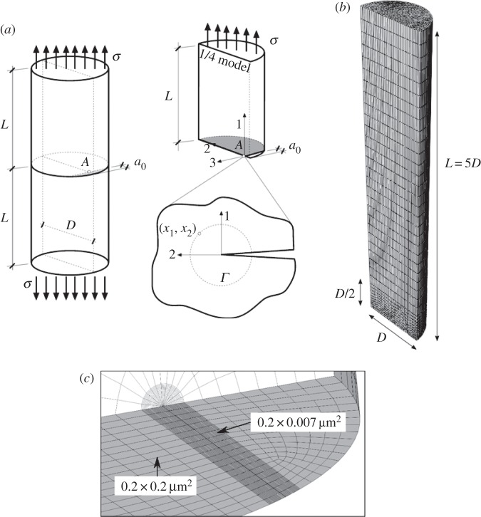
where KI stands for the stress intensity factor determined from the specimen geometry, the crack depth and the far-field stress applied. The factor Y (a/D) is also known as the non-dimensional stress intensity factor or shape factor. The stress intensity factor SIF for a straight-fronted edge crack introduced in a cylinder subjected to uniaxial tension along its axis was determined numerically by using the finite-element method [4,5]. The geometry of the specimen is plotted in figure 3a. A planar straight-fronted crack of depth a0 is placed perpendicular to the loading axis of the fibre of diameter D. For the sake of simplicity, only a quarter of the fibre was analysed, thanks to the symmetry of the problem, as shown in figure 3b. The fibre length 2L=10D was large enough to assume far-field loading conditions at the boundaries where a uniform axial stress σ is imposed without displacement and rotation constraints at the edges. The relative crack-to-diameter ratio varied in the range of a0/D=0–0.2, according to the aforementioned experimental results. It should be mentioned that both carbon and aramid fibres exhibited strong anisotropic behaviour, mainly owing to their microstructure and chains orientation, whereas the amorphous structure of the glass could be considered elastically isotropic. Carbon and aramid fibres will be assumed to behave as transversely isotropic solids, with the 2–3 being the isotropy plane and 1 the fibre direction [6,7]. The properties used in the simulation are summarized in table 3. In all the cases, given that the fibres will be homogeneous the spatial changes in the properties within the fibres owing to their own microstructure are not accounted for (for instance, the sheath/core structure).
Figure 3.
(a) Geometrical model of the notched fibre and detail of the Γ contour for J integral evaluation, (b) finite-element meshing of the crack tip region, (c) global finite-element meshing of the 1/4 model.
Table 3.
Elastic properties of fibres used in the simulations.
| fibre type | E1 (GPa) | E2=E3 (GPa) | ν12=ν13 | ν23 | G12=G13 (GPa) | G23(GPa) |
|---|---|---|---|---|---|---|
| AS4 carbon | 229 | 12.9 | 0.3 | 0.46 | 11.3 | 4.45 |
| E-glass | 68 | 68 | 0.3 | 0.3 | 26.1 | 26.1 |
| Kevlar KM2 | 84 | 1.34 | 0.0095 | 0.24 | 24.4 | 0.54 |
The particular symmetry boundary conditions used to simulate a state of uniaxial tension for the cracked fibre were u3=0 on x3=0 and u1=0 on the crack plane x1=0 and x2>0. In addition, a uniform normal traction stress σ was imposed in the upper part of the fibre on x1=L. The geometry of the fibre was first partitioned by using a cylinder following the crack tip direction in order to enrich the discretization around the crack tip and capture the large stress gradients in this region (figure 3b). Swept and structured meshes were used, respectively, to discretize the cylindrical region, with the remaining volume of the fibre using eight-noded isoparametric brick elements in Abaqus/Standard [8]. A mesh sensitivity analysis was also performed, obtaining an error below 0.5% in the J-integral calculation with the final discretization where 160 000 nodes were used (figure 3c). Simulations were carried out by using Abaqus/Standard within the framework of the small deformation theory.
The toughness evaluation for the given configuration was carried out and based on the J-integral, which is the standard approach in characterizing the energy release rate associated with a potential crack growth in LEFM (J=G in perfectly brittle materials). In such a case, the energy release rate J is obtained by integration along the contour Γ (figure 3a) according to
 |
3.3 |
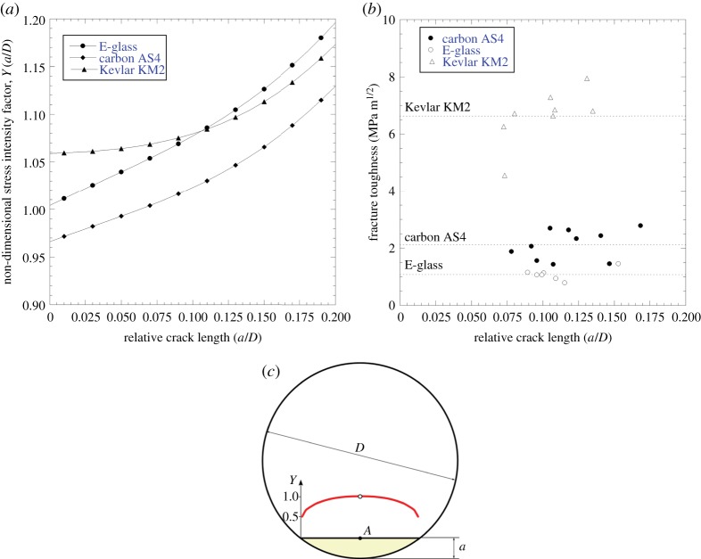
where W is the elastic strain energy density and t and u the traction and displacement vectors along the contour. Even though the J-energy release rate is path independent, several concentric Γ contours surrounding the crack tip are used because of the numerical nature of the finite-element solution. In addition, J-integral values are not constant along the crack length, with the finite-element model being focused on the maximum value attained at the symmetry plane (point A in figures 3a and 4c). The stress intensity factor at point A was determined from the J-integral by using the following Irwin’s relation for anisotropic solids derived by Sih et al. [9]
 |
3.4 |
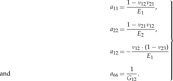
where KI stands for the stress intensity factor in mode I and aij stands for the compliance tensor of the anisotropic solid under plane strain
 |
3.5 |
This expression yields the traditional Irwin relation for isotropic solids J=K2/E′, where E′is the effective elastic modulus under plane strain E′=E/(1−ν2). The non-dimensional stress intensity factor Y (a/D) is plotted in figure 4a for the three structural fibres analysed in this paper by using the transversely isotropic constants gathered in table 3. The values of the fibre toughness for the given initial notch depth were determined through use of the corresponding non-dimensional stress intensity factors determined with the FEM model and the residual strength of the fibres (summarized in table 2). The lowest toughness values were obtained for the E-glass fibres, 1.08±0.14 MPa√m, and were similar to those reported in the literature [3] and slightly higher than soda lime glasses tested by nano-indentation [10]. High-strength Toray T700 FIB notched carbon fibres were tested by Kant & Penumadu [11] and the results obtained, 1.73±0.11 MPa√m, were similar to those reported here for AS4 carbon fibre, whereas Tanaka et al. [12] reported slightly lower values of the order of 1.1 MPa√m for other PAN-based carbon fibres (high-strength T800G and high modulus M30S, M40S and M50S).
Figure 4.
(a) Non-dimensional stress intensity factors for a straight-fronted crack for the three types of fibres, (b) fracture toughness of the three types of fibres, (c) typical stress intensity factor (red) variation along the chord of the circumference. Maximum non-dimensional stress intensity factor located at point A. (Online version in colour.)
The results of the fracture toughness of the three fibres were plotted as a function of the relative notch size, in order to determine whether or not the microstructure played a role (figure 4b). The calculated values of fibre toughness were almost insensitive to the notch depths for the typical depths analysed in the tests. These results are unsurprising for the case of the amorphous structure such as that in E-glass fibres, but may occur in highly anisotropic fibres such as aramid and carbon that could exhibit a sheath/core structure resulting from the manufacturing process. In any case, the notches introduced in the fibres in this work exceed this initial skin effect and the toughness obtained can be considered a homogeneous property corresponding to the central core of the fibre. This effect has also been reported by other authors [11], suggesting a skin thickness in high-strength T700 carbon fibres of the order of ≈300 nm, which is somewhat lower than the average notch depth used in this study (a0≈0.9 μm).
4. Discussion
The morphology of the fracture surface analysed after fibre testing reveals the dissipation mechanism nature for each fibre. The size of the damage/plastic process zone ahead the notch tip lp can be estimated according to the well-known Irwin relation as
 |
4.1 |
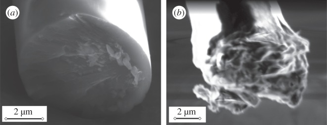
where KIC stands for the fracture toughness shown in table 2, and σ0 is the average tensile strength of the Weibull distribution (table 1). This estimate is useful in determining whether or not the notched fibre strength is dictated by the stress singularity at the crack tip given by the LEFM. All the results are gathered in table 2. Unsurprisingly, the plastic radius lp was well below the fibre diameter D, with the ratio being lp/D≈0.013 and 0.0095 for the AS4 carbon and E-glass fibres, respectively, indicating essentially brittle Irwin behaviour of both kinds of fibres. In the case of the E-glass fibres, the amorphous structure promotes crack propagation through a single mirror-like cleavage plane, as shown in figure 5a, dissipating the smallest amount of energy per surface unit corresponding to a brittle response.
Figure 5.
Post-mortem SEM micrographs of the fracture surface of tested notched fibres: (a) E-glass and (b) Kevlar KM2.
The fracture surface of the AS4 carbon fibres was also as flat as in the previous case, although a smooth granular morphology was observed. This showed how the origin of crack propagation was found at the midpoint of the artificial notch, as demonstrated in the numerical simulations required for the non-dimensional stress intensity factor calculation (figure 4c). This morphology is typical of PAN-based carbon fibres, as noted by other authors [11,13]. The plastic zone radius of the Kevlar KM2 fibres inferred from the tests results was lp/D≈0.081, significantly higher than the latter two cases analysed. In this case, the residual strength of the Kevlar KM2 notched fibres was not significantly affected by the presence of the defect introduced, suggesting involvement of other nonlinear energy dissipation mechanisms (3194 and 3816 MPa for notched and un-notched strength, respectively). This notch insensitivity behaviour could be attributed to the fibrillated structure that allowed sliding mechanisms in the fibre direction, which could produce a homogenization of the stress field around the notch region [7,14]. As a result, individual bundles of the aramid fibre were loaded almost homogeneously and regardless of the presence of the notch, resulting in a less sensitive behaviour of the fibre (figure 6b). As a result, Kevlar KM2 fibres presented the highest toughness compared with carbon and glass fibres, with this phenomenon being better understood by observing the fractured region of these fibres (figure 5b). In this case, the fracture process involves energy dissipation through a larger volume of fibre, in addition to a planar fracture surface in the form of plastic deformation and damage around the fractured region (multichain breakage-slippage, figure 6b). The fibre recoil after breakage can be explained by means of the elastic shockwave generated with the fracture process. Such a shockwave subjects the fibre to a high stress level, reaching large plastic deformations and permanent bending.
Figure 6.
(a) Coil-shaped Kevlar KM2 fibre after fracture, (b) sketch of fibril sliding mechanisms in Kevlar KM2 fibre.
5. Conclusion
Tensile tests on notched and un-notched carbon AS4, E-glass and Kevlar KM2 were carried out to determine strength and toughness. Notches of a0/D≈0.1 (a0 crack depth and D fibre diameter) were introduced in individual fibres by means of the FIB, which allows modification of the geometry of the fibres by selective removing/carving material. This technique opens revolutionary possibilities in machining complex geometries to determine physical parameters of materials at the microlevel. It should be noted that the FIB carving method infers damage/microstructural changes that could be partially alleviated by the selection of the appropriate beam current. The toughness and fracture energy of each fibre was determined from the residual strength of the notched fibres and the stress intensity factors obtained by means of the finite-element method. To this end, a fronted-end notch cylinder was subjected to uniform tensile stress, and the energy release rate and the non-dimensional stress intensity factors were determined numerically. The toughness of the AS4 carbon and E-glass fibres, 2.12±0.45 and 1.08±0.14 MPa√m, respectively, was similar to the values reported in the literature using similar techniques, based on the focus ion beam or on the analysis of the mirror surfaces in post-mortem composite specimens subjected to tensile stress. The brittleness of these fibres was determined with the aid of Irwin’s plastic radius, being considerably small when compared with the fibre diameter in these two fibres. The fracture surfaces of the E-glass and AS4 carbon fibres were essentially planar, with small irregularities being caused by the rapid propagation of the crack and material inhomogeneity. On the contrary, when testing Kevlar KM2 fibres, the material was less sensitive to the presence of the notch and the residual strength did not strongly change with respect to the un-notched configuration. As a result, the experimental measurement of the fracture toughness assuming linear elastic fracture mechanics was notably higher than the two previous fibre cases analysed.
Acknowledgements
The help of Dr Jon Molina and Prof. J. LLorca in the experimental work discussion is also acknowledged.
Authors' contributions
M.H. and A.F. performed the experimental work. C.S.L. and C.G. conceived the study, prepared the results discussion and wrote the manuscript for submission. All authors gave final approval for publication.
Competing interests
We declare we have no competing interests.
Funding
The authors are grateful to the Spanish Ministry of Economy and Competitiveness for support via the project MAT2012-37552. C.S.L. acknowledges the support of the Spanish Ministry of Economy and Competitiveness through the Ramón y Cajal programme.
References
- 1.Mueller MG, Pejchal V, Žagar G, Singh A, Cantoni M, Mortensen A. 2015. Fracture toughness testing of nanocrystalline alumina and fused quartz using chevron-notched microbeams. Acta Mater. 86, 385–395. ( 10.1016/j.actamat.2014.12.016) [DOI] [Google Scholar]
- 2.Slusarksi KA, Walter MS, Bogetti TA, Wetzel ED.2014. In-plane shear properties of high-performance filaments. In Fracture and fatigue, vol. 7: Proc. of the 2013 Annual Conf. on Experimental and Applied Mechanics (ed. C Jay), pp. 91–96. Cham, Switzerland: Springer International Publishing. ()
- 3.Wallenberger FT, Watson JC, Li H. 2001. Glass fibres. ASM Handb. Compos. 21, 27–34. [Google Scholar]
- 4.Guinea GV, Rojo FJ, Elices M. 2004. Stress intensity factors for internal circular cracks in fibres under tensile loading. Eng. Fract. Mech. 71, 365–377. ( 10.1016/S0013-7944(03)00115-2) [DOI] [Google Scholar]
- 5.Toribio J, Álvarez N, González B, Matos JC. 2009. A critical review of stress intensity factor solutions for surface cracks in round bars subjected to tension loading. Eng. Fail. Anal. 16, 794–809. ( 10.1016/j.engfailanal.2008.06.023) [DOI] [Google Scholar]
- 6.Cheng M, Chen W, Weerasooriya T. 2005. Mechanical properties of Kevlar KM2 single fiber. ASME J. Eng. Mater. Technol. 127, 197–203. ( 10.1115/1.1857937) [DOI] [Google Scholar]
- 7.Bencomo-Cisneros JA, Tejeda-Ochoa A, García-Estrada JA, Herrera-Ramírez CA, Hurtado-Macías A, Martínez-Sánchez R, Herrera-Ramírez JM. 2012. Characterization of Kevlar-29 fibres by tensile tests and nanoindentation. J. Alloys Compounds 536, S456–S459. ( 10.1016/j.jallcom.2011.11.031) [DOI] [Google Scholar]
- 8.Abaqus. Analysis user’s manual, v. 6.13. Providence, RI: Simulia, 2014.
- 9.Sih GC, Paris PC, Irwin GR. 1965. On cracks in rectilinearly anisotropic bodies. Int. J. Fract. Mech. 1, 189–203. ( 10.1007/BF00186854) [DOI] [Google Scholar]
- 10.Gong J, Chen Y, Li C. 2001. Statistical analysis of fracture toughness of soda-lime glass determined by indentation. J. Non-Crystall. Solids 279, 219–223. ( 10.1016/S0022-3093(00)00418-X) [DOI] [Google Scholar]
- 11.Kant M, Penumadu D. 2013. Fracture behavior of individual carbon fibres in tension using nano-fabricated notches. Compos. Sci. Technol. 89, 83–88. ( 10.1016/j.compscitech.2013.09.020) [DOI] [Google Scholar]
- 12.Naito K, Tanaka Y, Yang J-M, Kagawa Y. 2008. Tensile properties of ultrahigh strength PAN-based, ultrahigh modulus pitch-based and high ductility pitch-based carbon fibres. Carbon 46, 189–195. ( 10.1016/j.carbon.2007.11.001) [DOI] [Google Scholar]
- 13.Ogihara S, Imafuku Y, Yamamoto R, Kogo Y. 2009. Application of FIB technique to introduction of a notch into a carbon fiber for direct measurement of fracture toughness. J. Phys. Conf. Ser. 191 ( 10.1088/1742-6596/191/1/012009) [DOI] [Google Scholar]
- 14.Panar M, Avakian P, Blume RC, Gardner KH, Gierke TD, Yang HH. 1983. Morphology of poly(p-phenylene terephthalamide fibres. J. Polym. Sci. Polym. Phys. Edition 21, 1955–1969. ( 10.1002/pol.1983.180211006) [DOI] [Google Scholar]


