Abstract
The subject of this work is the investigation of the influence of voids on the mechanical properties of fibre-reinforced polymers (FRPs) under compression loading. To specify the damage accumulation of FRPs in the presence of voids, the complex three-dimensional structure of the composite including voids was analysed and a reduced mechanical model composite was derived. The hierarchical analysis of the model composite on a micro-scale level implies the description of the stress and strain behaviour of the matrix using the photoelasticity technique and digital image correlation technology. These studies are presented along with an analytical examination of the stability of a single fibre. As a result of the experimental and analytical studies, the stiffness of the matrix and fibre as well as their bonding, the initial fibre orientation and the fibre diameter have the highest impact on the failure initiation. All these facts lead to a premature fibre–matrix debonding with ongoing loss of stability of the fibre and followed by kink-band formation. Additional studies on the meso-scale of transparent glass FRPs including a unique void showed that the experiments carried out on the model composites could be transferred to real composites.
This article is part of the themed issue ‘Multiscale modelling of the structural integrity of composite materials’.
Keywords: effects of defects, voids, polymer composites, hierarchical analysis, fibre microbuckling, analytical approach
1. Introduction
The formation of voids cannot be avoided when manufacturing composite structures. Experimental studies as well as experience have shown that voids significantly affect the mechanical properties of composite laminates. In particular, the compressive strength of a laminate is reduced even at small void contents. As the mere reduction of the void content beyond a certain level is associated with exponentially increasing costs, the focus today is to get a better understanding about void formation and void impact on failure initiation and propagation, especially.
The compressive strength is in fact a limiting design factor because of its poor performance in comparison with the very high tensile strength. Only ≈60% of the tensile strength could be reached [1]. A further reduction to 50% could be the result of defects like voids [2–4]. In previous works, most efforts were devoted to describing the influence of voids on fibre-reinforced polymer (FRP) properties as a function of void volume content. Particularly with regard to the compressive strength, the void content can have a significant influence as summarized by Schultheisz & Waas [5]. Bazhenov et al. [2] investigated both the link between compressive strength and void content as well as the influence of fibre diameter. They concluded that, for thicker fibre diameters, the compressive strength can not only be explained by microbuckling analysis. For modelling the influence, Lee & Soutis [6] suggested to use the fibre microbuckling model by Budiansky [7] to indirectly predict the compressive strength in the presence of voids. Such an approach was first implemented by Gehrig [4] in which the reason for premature failure was disregarded.
To understand why void loaded composites fail or how failure mechanisms interact, it is necessary to reduce the complexity when modelling to a manageable amount, as reported by Liebig et al. [8]. This leads to the development of a hierarchical analysis on micro-, meso- and macro-scales to study the degradation of FRPs under the presence of voids as presented in this work.
2. Model composite
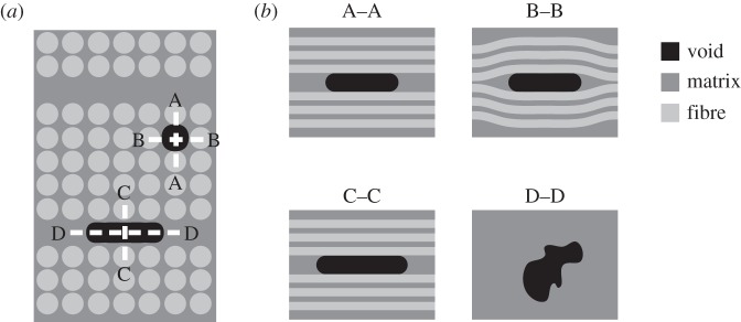
Owing to the complex morphology of FRP on the microstructure level, a model composite was developed. It allows one to study the material behaviour in the vicinity of a unique void and to observe the failure mechanisms under external loading. Based on previous investigations with the common prepreg material HexPly M21/35%/134/T800S (M21/T800S) provided by Hexcel Corporation, the void morphology was determined. Therefore, the autoclave pressure was varied during curing between 7, 5, 3 and 1 bar to achieve different void volume contents. The morphology and the position of voids inside the laminate were analysed by using light microscopy, scanning electron microscopy and microcomputer tomography. In real composites, there are three established methods to obtain this information non-destructively: X-ray and ultrasonic technology as well as optical coherent tomography. Within FRP one could distinguish between two different void configurations: intralaminar and interlaminar, as schematically shown in figure 1 [8,9].
Figure 1.
(a) Conformal sketch of intralaminar (sections A and B) and interlaminar (sections C and D) voids and (b) the cross sections through void inclusions [8].
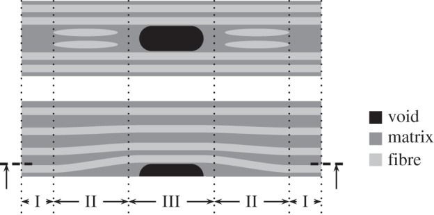
Intralaminar voids occur between fibres exhibiting a high length/width ratio, whereas interlaminar voids can be observed in resin-rich areas squeezed between plies, typically showing an irregular shape. Characteristics of the void geometry, i.e. length, width and height, can be defined as its elongation in the fibre direction and dimension in plane and out of plane of the laminate, respectively. However, both void configurations could be consolidated by a representative model composite, as shown in figure 2. The overall cross section is divided into three areas: area I is characterized by parallel fibres with perfect alignment, whereas due to the displacements of the void inclusion the fibres show a slight waviness or misalignment in area II. For both areas many publications can be found describing the influence of fibre orientation on the composite behaviour under compression load [7,10–12]. In this work, we focus on the direct void, area III.
Figure 2.
(a). Analytical approach
A minimized number of constituents leads to a model composite, as shown in figure 3. The model consists of a beam (fibre) embedded in the matrix. For both fibre and matrix, i.e. beam and foundation, small deformation and linear elastic and isotropic material behaviour is assumed. Fibre deformation is adopted by Timoshenko’s theory [13,14], while the matrix is represented by the elastic foundation of Winkler [15] and Pasternak [16].
Figure 3.
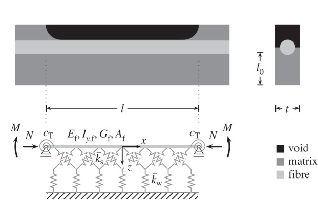
Sketch of the developed model consisting of a Timoshenko beam on a Winkler/Pasternak foundation.
The potential energy Π of an axially loaded fibre on Winkler/Pasternak foundation is the sum of the elastic strain energy U and the work of loads W,
| 2.1 |
The elastic energy consists of
 |
2.2 |
while the work of loads could be described as
 |
2.3 |
where w(x) is the deflection, Ef is Young’s modulus, Iy,f is the moment of inertia, Gf is the shear modulus and Af is the cross section of the fibre. Corresponding to that, the properties of the matrix are represented by the Winkler foundation  and the Pasternak foundation
  . Owing to the uncertainty of the support and its influence on the region, a torsion spring cT is designated on both sides of the fibre. At the end of the fibre, the axial force N and the bending moment M are applied. For the determination of the deformation of the fibre, a sinusoidal solution is chosen which gives exact results when the Ritz method is used. The deflection w(x) and the angle of the neutral axis ψ(x) perpendicular to the fibre are given by
 |
2.4 |
where am and bm represent the amplitude of the deflection and rotation, respectively, and m/l the wavelength of the fibre. The boundary conditions of the model are
 |
2.5 |
As a result of the integration and derivation the potential energy Π (equation (2.1)) can be written as
 |
2.6 |
depending on the unknown coefficients am and bm. If it is assumed that the moment M is negligible, the critical buckling load Ncr can be derived from the minimum of the potential energy,
 |
2.7 |
to be
 |
2.8 |
In this equation, NE describes the case of Euler buckling (NE=π2/l2EfIy,f) of a fibre pinned at both ends [17]. In general, it is considered that for l→0 the equation leads to
| 2.9 |
and for  , the critical buckling load becomes
| 2.10 |
Using the definition of Winkler/Pasternak foundation  and
and  it can be shown that the critical buckling load depends on the thickness of the matrix layer l0 and the effective width of the fibre foundation b(df). According to the size of l0, the first or the second term of equation (2.10) will vanish, respectively. However, in the case of an eccentricity load, a moment M exists and a non-trivial solution for am and bm out of the potential energy Π can be derived as
| 2.11 |
In this case, a0 is considered as the initial deflection of the fibre.
(b). Experimental study
(i). Materials and sample preparation
To support the analytical approach a model composite was adapted and manufactured as presented by the authors in [8,9]. It consists of E-glass fibres provided by P-D Glasseiden GmbH (Oschatz, Germany) with a mean diameter of  embedded in an epoxy matrix, RIM135 provided by Hexion (Germany). During sample preparation an air bubble was injected into the liquid epoxy using a syringe and squeezing the air bubble between the fibres. This procedure allows one to manufacture specimens consisting of a unique void embedded between two fibres rather than between two rovings. Followed by a curing process at 80°C for 15 h, as recommended by the resin manufacturer, the specimens are removed from the mould, dressed and prepared for testing, as shown in figure 4.
Figure 4.
Sketch of model composite specimens consisting of a unique void squeezed between (a) two/few fibres or (b) two rovings, respectively.
(ii). Compression tests
The compression tests were carried out using a test rig fitting in a transmission light microscope. All specimens were stabilized using an anti-buckling guide. The load was transferred via the end faces (figure 4a) of the specimens or end tabs (figure 4b), respectively. A cut-out within the anti-buckling guide allowed in situ observations using photoelasticity and digital image correlation (DIC; Aramis, provided by GOM mbH). All measured data of force and displacement were recorded continuously with the DigiVision v. 2011.1.0 software provided by Burster.
3. Results
(a). Analytical approach
The critical buckling load Ncr of a single fibre in the vicinity of a void could be determined using equations (2.8) and (2.10). In this case, the fibre will lose stability immediately after the critical buckling load is exceeded. There are two states of equilibration:
(i) stable (below critical buckling load) and
(ii) unstable (deflection will become infinite).
Figure 5 shows the compressive load ratio ηN, i.e. compressive load N divided by the critical buckling load Ncr, as a function of the length l of a half-embedded fibre. As highlighted in figure 5, the length l* characterizes the intersection point between the wrapped curves based on equations (2.10) and (3.1):
 |
3.1 |
Figure 5.
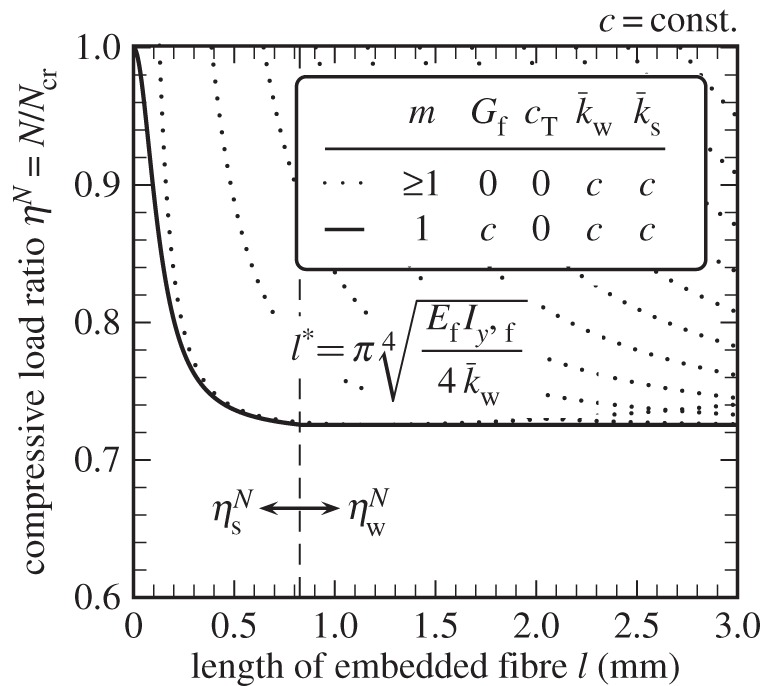
Compressive load ratio ηN as a function of half-embedded fibre length l.
For l<l*, the buckling load is dominated by the shear properties of the constituents (fibre and matrix) as well as the flexural property of the fibre. Whereas for l>l*, the stiffness of the matrix Em, including Winkler foundation  , becomes more significant. It should be mentioned that the compressive load ratio
  is independent of the length of the embedded fibre.
Derived from equation (3.1), it is obvious that the buckling behaviour of the fibre is affected by the Winkler/Pasternak foundation modulus  and
and  , respectively. Owing to the two-dimensional view, both parameters are dependent on the effective foundation width b of the matrix. Simplified, the matrix cross section could be reduced to the product of foundation thickness l0 and foundation width b, as shown in figure 6. In addition, the effective foundation width is based on the foundation angle α. Beside the schematic illustration a light microscopy image of a carbon-fibre-reinforced polymer (CFRP; M21/T800S) cross section in the presence of a void was taken to highlight the scope of the fibre foundation. Unsupported fibres and half- or almost fully embedded fibres are detectable.
Figure 6.
(a) Foundation angle α of a fibre dependent on foundation width b(df). (b) Light micrograph of a CFRP (M21/T800S) cross section in the presence of a void highlighting the scope of the fibre foundation.
The influence of the effective foundation width b or the foundation angle α on the foundation modulus  and
and  , respectively, is shown in figure 7. Therefore, equation (3.2), which depends on the effective foundation width, was referred to a full embedded fibre:
 |
3.2 |
The effective foundation width b could be determined in a simplified view to
 |
3.3 |
In particular, the compressive load ratio ηα (equation (3.2)) depends on the variable foundation thickness l0. For small values of l0 the compressive load ratio ηα becomes
 |
3.4 |
whereas for large values of foundation thickness l0, the second term of equation (3.2) dominates,
 |
3.5 |
Equations (3.4) and (3.5) form limiting curves, as shown in figure 7. In general, the compressive load ratio ηα increases with increasing foundation thickness from the basis  to
to  . In the case of half-embedded fibres, the influence of the foundation thickness is clearly visible. However, the critical compressive load ratio
  reaches 70%, whereas the compressive load ratio
  is only 50% of the maximum load.
Figure 7.
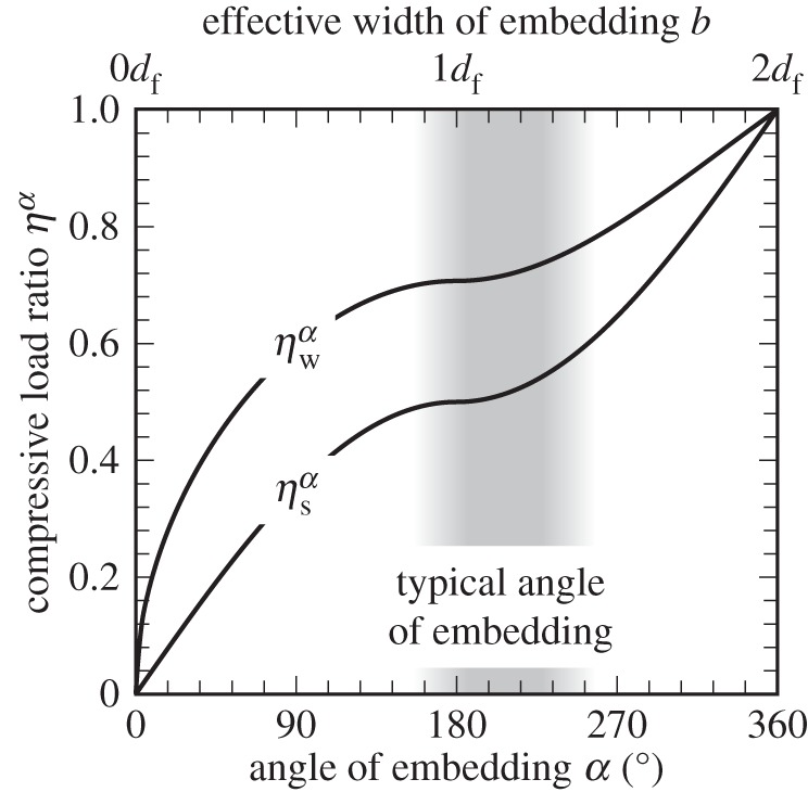
Compressive load ratio ηα as a function of the foundation angle α.
The comparison between the effective foundation and the influence of fibre orientation is a subject of special interest. Using the assumption of elliptical cross sections of voids, the foundation angle of single fibres is conducted to α>180°, so that the compressive load ratio could be fixed to 0.5 and 0.7, respectively.
In the previous section, it was assumed that the applied moment is negligible. In that case the fibre changes the state of equilibration immediately from stable to unstable. However, owing to void inclusions, the load introduction is hardly perfect, so it is necessary to identify the influence of an applied moment. For example, voids could cause a fibre misalignment leading to a distorted or an eccentric load introduction, respectively. The applied load N induces a bending moment M, which leads to a further distortion of the fibre am. Figure 8 shows the compressive load ratio ηϕ based on equation (2.11) as a function of the relative fibre orientation ϕ0+ϕm. With increasing compressive load ratio ηϕ, the relative deflection also increases. For all cases shown in figure 8 (dashed lines), the compressive load ratio converges asymptotically to the critical buckling load of the perfectly aligned fibre. To determine the point at which the curves become physically relevant, it is necessary to draw down curves of stress [18]. Owing to its distortion the compressive stress ratio ησ could be calculated by the superposition principle between compressive and bending loads. Based on linear elastic material behaviour, the compressive load ratio ησ can be determined from fibre failure in compression and the applied stress, respectively [18–20]. Then, the compressive load ratio ησ (equation (3.6)) can be simply written as
 |
3.6 |
where a0/l+am/l can be transferred to fibre orientation angle ϕ0+ϕm. Two typical  ratios (glass fibre
  and carbon fibre
  depending on length of void lv=0.1 mm and lv=1.0 mm, respectively [21]) are plotted as hyperbolae (solid lines) in figure 8. This approach of Mies [18] and Hahn [20] is concluded as acceptable, to determine the compressive strength of a 0° unidirectional laminate by Berbinau et al. [22]. However, in this case figure 8 clearly illustrates that the fibre diameter has a significant influence on failure behaviour under compressive load, which was neglected by the approach of Argon [23] and Budiansky [7].
Figure 8.
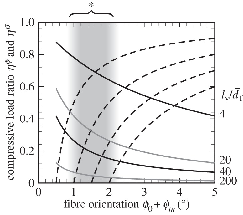
Compressive load ratio ηϕ and ησ as a function of relative fibre orientation ϕ0+ϕm and fibre diameter (glass fibre  and carbon fibre
  ). Asterisk denotes typical range of ϕ0, see also table 1.
(b). Experimental study
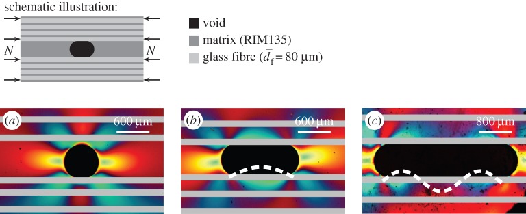
The experimental study on micro- and meso-scales allows the investigation of the stress conditions, failure initiation and the failure propagation due to void inclusions. Therefore, a photoelastic as well as a DIC study of the model composites as a function of several aspect ratios of the void (length/width: lv/bv) were performed, as shown in figures 9 and 10, respectively. In this case, it should be mentioned that the photoelasticity was used to visualize the stability behaviour of the fibre. The dashed lines represent the stress-induced buckling of the fibres. It could be observed that along the void inclusion different fringe patterns occur. Especially for a void aspect ratio >1 typical shapes of stress concentrations appear (blue colour online) around the void and along its closest fibre, which offers valuable hints to the buckling of the fibres. Similar results concerning the photoelastic pattern of fibres under compression were observed by Rosen [10], who investigated the compressive behaviour of composites on fully embedded fibres. It can be concluded that the reduced support of fibres leads to buckling of fibres near the voids.
Figure 9.
Photoelastic study (white light) of model composite (eight fibres) depending on aspect ratio of the void. (a) lv/bv=1 (N=260 N); (b) lv/bv=2.3 (N=250 N) and (c) lv/bv=3.8 (N=276 N) [8].
Figure 10.
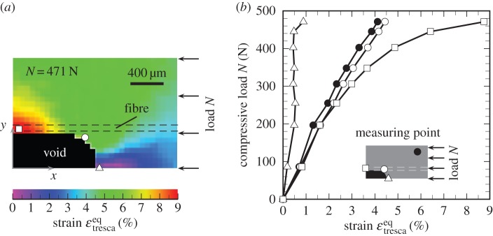
Contour plot (DIC measurement) of strain in the vicinity of a unique void (a) and selected measuring points of strain dependent on the compressive load (b).
Further experimental studies on model composites (micro-scale) were performed using DIC evaluation (Figure 10) shows a contour plot of the equivalent strain εeqtresca on the surface of the model composite (figure 10a) and a diagram of selected measuring points of interest (figure 10b). The minimum and maximum strain are located in the summit (εeq,mintresca=0.2%) and in the middle (εeq,maxtresca=8.7%) of the void, respectively. In contrast with observations based on photoelasticity, shear stresses (circles) induced by stress rearrangements at the end cap of the void are negligible. Thus, the maximum strain is dominated alongside the void from fibres deflected into the void initiating fibre kinking (squares). At this point, the matrix deforms already nonlinearly, even at low compressive load (N=325 N or rather σc=40 MPa).
The failure initiation and propagation could also be conducted on meso-scale (model composites manufactured using rovings instead of a few fibres). Figure 11a shows the cross section of a model composite in which a kink-band has been formed. As pointed out in figure 9c, the fibre kinking took place alongside the void at a point of high stress concentration. It seems that first a damage zone is formed, as shown in figure 11b in the background, followed by kinking of fibres near the void into the free volume [8,24].
Figure 11.
(a) SEM picture of a cross section of a model composite showing a kink-band and (b) high magnification of kink-band.
4. Discussion
(a). Representativeness of the model
The assumptions based on CFRP laminates may be too simple to represent real composites containing voids. However, the derived model (figure 2) could also be found at a cutaway view of CFRP, published in a separate paper [8]. Particularly, for third-generation prepreg systems the formation of voids partly takes place within resin-rich areas [25]. Thus, the absolutely reduced model (focusing on area III, figure 3) is also reasonable. In this case, one has to think about the assumption seriously that fibres are adapted to void geometry as a sinusoidal curve, as shown in other publications [4,26]. Owing to the fact that interlaminar voids hardly affect the fibre orientation, an estimation of the compressive strength based on fibre orientation alone would be inappropriate.
In general, the specimens were manufactured by using glass fibres and rovings, respectively. This allows the investigation of stress–strain conditions in the matrix around a unique void by using optical evaluation methods such as light transmission microscopy, photoelasticity and DIC. These investigations also show that the analytical approach should be extended by implementing nonlinear material behaviour of the matrix if the compressive strength could be predicted.
(b). Compressive failure in the presence of voids
Assuming there are two types of voids (intralaminar and interlaminar) most of them occur between plies in resin-rich areas [21,27,28]. However, it is obvious to apply an established theory, like Budiansky’s approach [7], to predict the compressive strength indirectly for composites containing voids, as suggested by Lee & Soutis [6]. Therefore, the initial fibre orientation has to combine with the void content. Assuming a Gaussian distribution, the standard deviation of fibre orientation is determined based on studies on M21/T800S by using Yurgartis’ method [29,30]. This is summarized in table 1. Taking into account an initial fibre orientation of ϕ0=1°–2°, this practice would lead to a reduction of the compressive strength of less than 30%, depending on fibre diameter (cf. figure 8). Given that the fibre diameter is not considered in Budiansky’s theory, the resistance of thick fibres against microbuckling could not be taken into account anyway [2]. In addition, with increasing fibre alignment the compressive load ratio will decrease asymptotically to a negligible value. Hence, the compressive load ratio would be underestimated.
Table 1.
Standarddeviation of fibre misalignment in plane  and out of plane
  depending on void content vv. Measurement data of fibre misalignment are based on studies on M21/T800S by using Yurgartis’ method [29,30].
| void content, vv (%) | ≤0.1 | 2.7 | 6.8 | 9.0 |
| autoclave pressure (bar) | 7 | 5 | 3 | 1 |
fibre misalignment,  (°) (°) |
0.9 | 1.1 | 0.8 | 1.3 |
fibre misalignment,  (°) (°) |
1.3 | 1.4 | 1.5 | 2.8 |
In general, just a couple of publications could be found with experimental data1 about compressive strength as a function of void contents between vv=0% and ≈25%, as summarized in figure 12. In combination with findings of failure initiation, as shown in figure 11 and presented in [8], equation (3.2) leads to a minimum in compressive strength η≈50% for half-embedded fibres. As observed in experimental studies for model composites at the micro- and meso-scale levels, the failure initiation is caused by fibre–matrix debonding [32–34], which could be pushed by fibre misalignment, followed by kink-band formation [8,26]. This leads to the assumption that the foundation (fibre–matrix bond) dominates the failure process.
Figure 12.
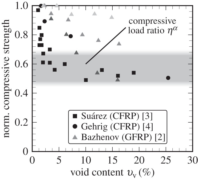
Normalized compressive strength of different composite laminates depending on void content [2,3,4]. Measurement data: Gehrig (CFRP) are mean values, whereas Bazhenov (GFRP) also investigated the influence of fibre diameter:  (black triangle), 80 μm (dark grey triangle) and 130 μm (light grey triangle).
(c). Transfer from model to real composite
The role of the matrix while loading is most important as it supports and controls the microbuckling behaviour of the embedded fibres, as shown in figures 9 and 10. In contrast with numerical studies in which just idealized models could be analysed, the simplicity of this approach allows one to investigate failure modes on model composites and to transfer the results to real composites. As shown in figure 11, failure initiation occurs in overloaded areas of the matrix (figures 9 and 10). Furthermore, the failure modes of composites [8] are in accordance with failure mechanisms on model composite [8].
Owing to the fact that the basic principles of the analytical approach are independent of mechanical properties for different materials (figures 7 and 8), the findings from this study should also be transferable to all fibre-reinforced materials.
5. Conclusion
For this work, a hierarchical approach was chosen to investigate the degradation process in composites containing void inclusions under compressive load. By using an analytical approach it could be shown that the mechanical behaviour of fibre-reinforced composites is significantly influenced by the stiffness of both matrix and fibre and the fibre–matrix bonding, further by the initial fibre orientation and the fibre diameter. Voids lead to local stress concentrations in the matrix which are enhanced by fibre distortion into the void volume. There are generally two different limiting factors influencing the compressive strength of composites in the presence of voids. First, the fibre orientation leading to premature microbuckling, particularly in the case of a low void content. Second, the embracement of fibres with matrix (angle of fibre embedded in the matrix) which can result in a 50% maximum loss of compressive strength. This is evident also from experimental data of several publications.
Finally, in the authors’ opinion, the determination of the compressive strength of composites in the presence of voids should consider not just the void content but more importantly the critical number of affected fibres using a probabilistic approach. Owing to the fact that the formation of voids cannot be avoided during the manufacturing process of composites, the presented approach has to be extended to further load cases, e.g. transverse tensile, shear loading. This would create the possibility to integrate a parameter of failure criteria to estimate the upper and lower bounds for critical loads in the phase of design. The precondition, therefore, is whether a critical size/position or certain amount of voids exists and how voids influence the mechanical behaviour under various load cases.
Footnotes
Owing to the fact that fibres were soaked in acetone before being saturated with resin to increase void contents, experimental data of Hancox [31] are not considered.
Authors' contributions
W.V.L. carried out the laboratory work with acquisition of data, modelling analysis and interpretation, and drafted the article; K.S. designed and coordinated the study, revised it critically for important intellectual content, and helped draft the manuscript; B.F. contributed to conception of research and interpretation of data. All authors gave final approval for publication.
Competing interests
The authors declare that they have no competing interests.
Funding
This work was carried out with funding from the European Commission (European Community’s Seventh Framework Programme FP7/2007-2013, MAAXIMUS) and German Research Foundation (DFG) PAK267 of the Project Schu 926/16.
References
- 1.Port KF. 1982. The compressive strength of carbon fiber reinforced plastics. Technical report no. 82083. Royal Aircraft Establishment, Farnborough, UK.
- 2.Bazhenov SL, Kuperman AM, Zelenskii ES, Berlin AA. 1992. Compression failure of unidirectional glass-fibre-reinforced plastics. Compos. Sci. Technol. 45, 201–208. ( 10.1016/0266-3538(92)90080-M) [DOI] [Google Scholar]
- 3.Suárez JC, Molleda F, Güemes A. 1993. Void content in carbon fibre/epoxy resin composites and its effects on compressive properties. In Proc. 9th Int. Conf. on Composite Materials (ICCM-9), Madrid, Spain, 12–16 July, vol. VI, Composites properties and applications (ed. A Miravete), pp. 589–596. University of Zaragoza; and Cambridge, UK: Woodhead.
- 4.Gehrig F. 2011. The influence of pores on the damage behaviour of carbon fibre-reinforced polymers. Ph.D. thesis, Technische Universität Hamburg-Harburg, Germany. [In German].
- 5.Schultheisz CR, Waas AM. 1996. Compressive failure of composites. Prog. Aerosp. Sci. 32, 1–78. ( 10.1016/0376-0421(94)00002-3) [DOI] [Google Scholar]
- 6.Lee J, Soutis C. 2007. A study on the compressive strength of thick carbon fibre–epoxy laminates. Compos. Sci. Technol. 67, 2015–2026. ( 10.1016/j.compscitech.2006.12.001) [DOI] [Google Scholar]
- 7.Budiansky B. 1983. Micromechanics. Comput. Struct. 16, 3–12. ( 10.1016/0045-7949(83)90141-4) [DOI] [Google Scholar]
- 8.Liebig WV, Viets C, Schulte K, Fiedler B. 2015. Influence of voids on the compressive failure behaviour of fibre-reinforced composites. Compos. Sci. Technol. 117, 225–233. ( 10.1016/j.compscitech.2015.06.020) [DOI] [Google Scholar]
- 9.Liebig WV, Leopold C, Schulte K. 2013. Photoelastic study of stresses in the vicinity of a unique void in a fibre-reinforced model composite under compression. Compos. Sci. Technol. 84, 72–77. ( 10.1016/j.compscitech.2013.04.011) [DOI] [Google Scholar]
- 10.Rosen BW. 1965. Mechanics of composite strengthening. In ASM Seminar on Fiber Composite Materials, Philadelphia, PA, 17–18 October 1964, pp. 37–75. Metals Park, OH: American Society for Metals.
- 11.Gutkin R, Pinho ST, Robinson P, Curtis PT. 2010. On the transition from shear-driven fibre compressive failure to fibre kinking in notched CFRP laminates under longitudinal compression. Compos. Sci. Technol. 70, 1223–1231. ( 10.1016/j.compscitech.2010.03.010) [DOI] [Google Scholar]
- 12.Wisnom MR. 1990. The effect of fibre misalignment on the compressive strength of unidirectional carbon fibre/epoxy. Composites 21, 403–407. ( 10.1016/0010-4361(90)90438-3) [DOI] [Google Scholar]
- 13.Engesser F. 1891. Die Knickfestigkeit gerader Stäbe. Zentralbl. Bauverwaltung 11, 483–486. [Google Scholar]
- 14.Timoshenko SP, Gere JM. 1961. Theory of elastic stability, 2nd edn New York, NY: McGraw-Hill. [Google Scholar]
- 15.Winkler E. 1867. Die Lehre von der Elasticitaet und Festigkeit mit besonderer Rücksicht auf ihre Anwendung in der Technik. Prague, Czech Republic: Dominicus. [Google Scholar]
- 16.Pasternak PL.1954. On a new method of analysis of an elastic foundation by means of two foundation constants. In Gosudarstvennoe Izdatelstvo Literaturi po Stroitelstvu i Arkhitekture. [In Russian.]
- 17.Euler L. 1744. Methodus Inveniendi Lineas Curvas Maximi Minimive Proprietate Gaudentes, Sive Solutio Problematis Isoperimetrici Latissimo Sensu Accepti. Lausanne, Switzerland: Marcum Michaelem Bousquet. [Google Scholar]
- 18.Mies O. 1912. Über das Ausknicken stabförmiger Körper. Dinglers Polytechnisches J. 327, 177–181. [Google Scholar]
- 19.Ostenfeld A. 1898. Exzentrische und zentrische Knickfestigkeit. VDI-Z 94, 1462–1470. [Google Scholar]
- 20.Hahn HT. 1987. Analysis of kink band formation under compression. In Proc. 6th Int. Conf. on Composite Materials and 2nd European Conf. on Composite Materials (ICCM-6/ECCM-2), London, UK, 20–24 July (ed. FL Matthews et al.), vol. 1, pp. 269–277. London, UK: Elsevier Applied Science.
- 21.Huang H, Talreja R. 2005. Effects of void geometry on elastic properties of unidirectional fiber reinforced composites. Compos. Sci. Technol. 65, 1964–1981. ( 10.1016/j.compscitech.2005.02.019) [DOI] [Google Scholar]
- 22.Berbinau P, Soutis C, Guz IA. 1999. Compressive failure of 0° unidirectional carbon-fibre-reinforced plastic (CFRP) laminates by fibre microbuckling. Compos. Sci. Technol. 59, 1451–1455. ( 10.1016/S0266-3538(98)00181-X) [DOI] [Google Scholar]
- 23.Argon AS. 1972. Fracture of composites. Treatise Mater. Sci. Technol. 1, 79–114. ( 10.1016/B978-0-12-341801-2.50007-2) [DOI] [Google Scholar]
- 24.Garland BD, Beyerlein IJ, Schadler LS. 2001. The development of compression damage zones in fibrous composites. Compos. Sci. Technol. 61, 2461–2480. ( 10.1016/S0266-3538(01)00176-2) [DOI] [Google Scholar]
- 25.Liebig WV, Gehrig F, Schulte K. 2010. Influence of voids on the behaviour of composites. In Proc. 14th Eur. Conf. on Composite Materials, Budapest, Hungary, 7–10 June (eds L Kollár, T Czigány, J Karger-Kocsis). Budapest University of Technology and Economics, Department of Polymer Engineering.
- 26.Hapke J, Gehrig F, Huber N, Schulte K, Lilleodden ET. 2011. Compressive failure of UD-CFRP containing void defects: in situ SEM microanalysis. Compos. Sci. Technol. 71, 1242–1249. ( 10.1016/j.compscitech.2011.04.009) [DOI] [Google Scholar]
- 27.Olivier P, Cottu JP, Ferret B. 1995. Effects of cure cycle pressure and voids on some mechanical properties of carbon/epoxy laminates. Composites 26, 509–515. ( 10.1016/0010-4361(95)96808-J) [DOI] [Google Scholar]
- 28.Howe CA, Paton RJ, Goodwin AA. 1997. A comparison between voids in RTM and prepreg carbon/epoxy laminates. In Proc. 11th Int. Conf. on Composite Materials, Gold Coast, Queensland, Australia, 14–18 July (ed. ML Scott), vol. IV, Composites processing and microstructure, pp. 46–51. Melbourne, Australia: Australian Composite Structures Society. See http://www.iccm-central.org/Proceedings/ICCM11proceedings/ICCM_11v4.pdf.
- 29.Yurgartis SW. 1987. Measurement of small angle fiber misalignments in continuous fiber composites. Compos. Sci. Technol. 30, 279–293. ( 10.1016/0266-3538(87)90016-9) [DOI] [Google Scholar]
- 30.Liebig W. 2014. A micromechanical approach to investigate the influence of voids on properties of fibre-reinforced polymers. Ph.D. thesis, Technische Universität Hamburg-Harburg, Germany. [In German].
- 31.Hancox NL. 1975. The compression strength of unidirectional carbon fibre reinforced plastic. J. Mater. Sci. 10, 234–242. ( 10.1007/BF00540347) [DOI] [Google Scholar]
- 32.Guz IA, Soutis C. 2000. Critical strains in layered composites with interfacial defects loaded in uniaxial or biaxial compression. Plastic Rubber Compos. 29, 489–495. ( 10.1179/146580100101541346) [DOI] [Google Scholar]
- 33.Guz IA, Soutis C. 2001. Predicting fracture of layered composites caused by internal instability. Composites A 32, 1243–1253. ( 10.1016/S1359-835X(01)00077-X) [DOI] [Google Scholar]
- 34.Soutis C, Guz IA. 2006. Fracture of layered composites by internal fibre instability: effect of interlaminar adhesion. Aeronaut. J. 110, 185–195. ( 10.1017/S0001924000001160) [DOI] [Google Scholar]


