

Abstract
The present work is a review of the substantial effort that has been made to measure and understand the effects of corrosion with respect to the properties, performance, and durability of various forms of silicon carbide and silicon nitride. The review encompasses corrosion in diverse environments, usually at temperatures of 1000 °C or higher. The environments include dry and moist oxygen, mixtures of hot gaseous vapors, molten salts, molten metals, and complex environments pertaining to coal ashes and slags.
Keywords: ash, ceramics, coal, corrosion, silicon carbide, silicon nitride, slag
1. Introduction
The present work is a review of the substantial effort that has been made to measure and understand the effects of corrosion with respect to the properties, performance, and durability of various forms of silicon carbide and silicon nitride. These materials are the primary candidates for the materials to be used in the development of heat exchangers for the Department of Energy’s Combustion 2000 program. The review encompasses corrosion in diverse environments, usually at temperatures of 1000 °C or higher. The environments include dry and moist oxygen, mixtures of hot gaseous vapors, molten salts, molten metals, and complex environments pertaining to coal ashes and slags.
The potential applications of advanced structural ceramics have been widely appreciated for several decades [1]. Characteristics such as high maximum use temperature, strength retention at high temperature, and chemical stability have held forth tantalizing possibilities [2,3] for more efficient engines [4], heat exchangers and recuperators [5,6] and for more durable electronic packaging [7] and chemical processing components [8]. The primary barriers that have impeded [9] the widespread development of these applications have been the susceptibility of structural ceramics to brittle fracture [10] and environmentally sensitive corrosion behavior [11], including the subsequent effects of corrosion on the thermal and mechanical performance of ceramics. The former barrier has received, by far, the greater amount of attention [12]. The corrosion of advanced ceramics, however, has proven to be a complex problem and has been recognized as a critical consideration in attaining high efficiency applications [13].
A schematic illustration of the corrosion process is shown in Fig. 1. The bulk ceramic material usually may be assumed to have a film or scale on its surface that differs chemically from the bulk material. For either silicon carbide or silicon nitride, the film is usually a critically important silica layer. The bulk ceramic and its surface scale form a solid body that is exposed to a hot, flowing, gaseous environment which may also contain fine particulate matter and from which a deposit may form on the solid body. This deposit may exist in a crystalline, glassy, or molten form at the principal exposure temperature.
Fig. 1.

Schematic illustration of various mechanisms involved in the corrosion of a ceramic material.
In this simple schematic, the corrosion process already can be seen to involve the possibility of a complex series of chemical reactions whose time-dependent course may be influenced by thermal and mechanical properties of the substrate, as well as the chemical composition of the environment. The diffusion of oxygen from the gaseous region to the ceramic, where oxidation can replenish the protective scale, may be dependent on the nature of the deposit, its density, and its thickness. Likewise, the direct and deleterious reaction between the deposit and the bulk ceramic may become possible through the formation of cracks in the protective film as a result of thermal stress gradients, the dissolution of the film in a molten deposit, and localized stress enhancement resulting from the evolution of gaseous reaction products at the interface of the ceramic and film.
The process illustrated by Fig. 1 represents the current view of the corrosion of silicon carbide quite well. For silicon nitride, the oxide scale is actually a double or duplex layer in which an intermediate phase of silicon oxynitride occurs between the outer silica scale and the silicon nitride substrate [14]. Details of the contributing and competing reactions, the formation kinetics, and the physical consequences of the corrosion process are reviewed in the following sections.
2. SiC
The reaction sequences for the corrosion of a material may be strongly affected by either the major or the minor components of its composition, and the rate of corrosion may be affected by the microstructure of the material. The composition determines what chemical species are available for reaction, and the structure determines how accessible the species are for the potential reactions. Consequently, understanding the corrosion of a material presupposes an understanding of the composition and structure of the material.
Crystalline silicon carbide exists in a large variety of polymorphic forms, or polytypes, that are broadly divided into two classes, α-SiC and β-SiC. The β-SiC class has a cubic structure, while the α-SiC class consists of hexagonal and rhombohedral noncubic structures. All of the varieties of SiC are formed by hexagonal layers of silicon atoms and hexagonal layers of carbon atoms arranged in various stacking patterns that result in each silicon atom being surrounded tetrahedrally by four carbon atoms, and each carbon atom being surrounded tetrahedrally by four silicon atoms. Specific varieties are commonly designated by a notation that (1) specifies the number of layers in the repeating unit and (2) indicates the symmetry of the crystallographic cell by a letter: C for cubic, H for hexagonal, and R for rhombohedral. The forms frequently noted in the literature include the cubic form, 3C of the β-SiC class, and the noncubic forms 2H, 6H, and 15R of the α-SiC class.
Powders in the β-SiC form may be produced at relatively low temperature, 1500–1600 °C, using polycarbosilanes and polyborosiloxanes in polymer conversion reactions [18], gaseous mixtures of silane, hydrogen chloride, propane, and hydrogen in vapor phase reactions [19], or low-temperature carbothermic reduction of silica and carbon with boron and titanium as additives [20]. The production of α-SiC is usually conducted at temperatures above 2500 °C and is most commonly produced using the carbothermic method known as the Acheson process [21]. Gas phase synthesis can also be used to produce α-SiC. At temperatures above 2000 °C, β-SiC may convert to α-SiC.
Bulk SiC ceramics are usually derived from SiC powders using various processing stages. As a result, SiC ceramics are generally polycrystalline materials that may consist of more than one polytype of SiC plus additional material phases resulting from the use of sintering aids or other components of the starting powders. The processing of the powders usually involves sintering, hot pressing, or reaction bonding. The sintering or hot pressing of SiC commonly requires the use of sintering aids such as boron or aluminum or their oxide, nitride, or carbide compounds. In the reaction bonding technique, carbon, silicon metal, silicon nitride, or other powders may be mixed with silicon carbide powder and allowed to react at high temperature. The resulting ceramic is generally a multiphase material that also may have a bimodal SiC grain size distribution.
It is evident that silicon carbide materials that are nominally the same may have significantly different impurities, grain size distributions, grain boundary phases, and types and extent of porosity. These differences are significant in the context of corrosion because of their influence on the possible reaction sequences, the diffusion rates of the reactants and products, and the occurrence of either localized pitting or uniform surface recession.
2.1 Oxidation of SiC
The oxidation of SiC has been a subject of considerable interest for many decades [24]. Over this period, the research efforts have shown a progression from studies of the coarser aspects of oxidation to more detailed investigations of contributing mechanisms. It was noted in an early work that the formation of SiO2 on the surface, Fig. 2, was probably the rate-controlling process in the normal oxidation of SiC [25]. According to the free energy changes, Table 1, the formation of SiO2 should result predominantly from the reaction
Fig. 2.

The oxidation of SiC powders, of various specific surface areas, in dry air at 1300 °C. (After G. Ervin, Jr., J. Am. Ceram. Soc. 44 (9), 347–352 (1958).)
Table 1.
Reactions of SiC with O2 and associated free energy changes, ΔFa
| ΔF (kJ/mol) | ||
|---|---|---|
| 25 °C | 1627 °C | |
| SiC + 2 O2→SiO2 + CO2 | −1168.0 | −901.2 |
| SiC+ (3/2) O2→SiO2 + CO | − 910.9 | −783.2 |
| SiC+O2→SiO2 + C | − 773.6 | −505.0 |
| SiC+(3/2)O2→SiO + CO2 | − 460.7 | −604.6 |
| SiC + O2→SiO + CO | − 203.3 | −486.6 |
| SiC+(l/2)O2→SiO + C | − 66.1 | −208.4 |
| SiC + O2→Si + CO2 | − 342.7 | −361.9 |
| SiC+(1/2) O2→Si + CO | − 85.4 | −243.9 |
After G. Ervin, Jr., J. Am. Ceram. Soc. 44 (9), 347–352 (1958).
In that same work, a weight loss, rather than a weight gain, was observed, Table 2, when SiC was heated in a vacuum. The suggestion was made that the formation of SiO gas was most likely responsible for the latter result, primarily from the reaction
In a later investigation of the kinetics of SiC oxidation, the oxidation process was resolved into passive and active processes as was done for the oxidation process of silicon [26]. The occurrence of a passive oxidation process, involving weight gain, or an active oxidation process, involving weight loss, Table 3, depended on the magnitude of the oxygen partial pressure [27]. The weight loss was again related to the formation of SiO gas, but the key reaction producing the SiO gas was thought to be
More generally, for a given temperature, it was found that the oxidation of SiC was passive unless the partial pressure of oxygen was less than a critical value. Alternatively, for a given partial pressure of oxygen, an active-to-passive transition temperature could be defined, Table 4, such that passive oxidation would occur at temperatures less than the transition temperature, while active oxidation would occur at higher temperatures [28].
Table 2.
The oxidation of high purity, 100–200 mesh SiC at low pressurea
| Air pressure (Pa) | Temperature (°C) | Exposure time (h) | Mass ehange (%) |
|---|---|---|---|
| 0.001 | 1600 | 16 | − 4.2 |
| 0.133 | 1600 | 17 | −19.9 |
| 13.332 | 1440 | 4 | − 2.5 |
After G. Ervin, Jr., J. Am. Ceram. Soc. 44 (9), 347–352 (1958).
Table 3.
Oxidation rate of high purity SiCa
| Pressure (Pa) | Temperature (°C) | O2 Flow rate (1017 molecules per second) | Mass gain (μg/s) |
|---|---|---|---|
| 1.2 | 1150 | 1.02 | 0.04 |
| 1.2 | 1200 | 1.32 | 0.05 |
| 1.2 | 1200 | 0.64 | 0.02 |
| 1.2 | 1250 | 1.10 | −0.19 |
| 1.2 | 1300 | 1.13 | −1.56 |
| 1.2 | 1350 | 1.04 | −1.65 |
| 1.2 | 1400 | 0.62 | −1.31 |
| 5.3 | 1150 | 8.4 | 0.52 |
| 5.3 | 1200 | 7.4 | 0.06 |
| 5.3 | 1250 | 10.5 | 0.97 |
| 5.3 | 1300 | 8.7 | −0.75 |
| 5.3 | 1350 | 9.3 | −0.86 |
| 5.3 | 1400 | 8.1 | −5.22 |
| 13.3 | 1150 | 52.5 | 3.6 |
| 13.3 | 1200 | 56.5 | 0.2 |
| 13.3 | 1250 | 56.5 | 0.8 |
| 13.3 | 1300 | 56.5 | 0.2 |
| 13.3 | 1350 | 64.0 | 3.9 |
| 13.3 | 1400 | 66.5 | −9.3 |
| 66.7 | 1150 | 6.3 | 0.2 |
| 66.7 | 1250 | 8.0 | 1.1 |
| 66.7 | 1300 | 7.6 | 0.6 |
| 66.7 | 1350 | 8.4 | 4.8 |
After E. A. Gulbransen et al., J. Elcetrochem. Soe. 113(12), 1311–1314 (1966).
Table 4.
Aetive-to-passive transition temperature, Tap, for sintered α-SiC at various values of the partial pressure of oxygen, P(O2)a
| Flow rate (cm3/s) | P(O2) (Pa) | Tap (°C) |
|---|---|---|
| 1.66 | 18.2 | 1403 |
| 1.66 | 18.8 | 1405 |
| 1.66 | 65.8 | 1532 |
| 1.66 | 125.1 | 1542 |
| 0.83 | 10.2 | 1389 |
| 0.83 | 55.6 | 1496 |
| 0.83 | 123.2 | 1543 |
| 0.56 | 7.3 | 1373 |
| 0.56 | 16.8 | 1392 |
| 0.56 | 61.6 | 1507 |
| 0.17 | 2.5 | 1347 |
| 0.17 | 17.6 | 1372 |
| 0.17 | 57.4 | 1468 |
| 0.17 | 115.9 | 1532 |
After W. L. Vaughn et al., J. Am. Ceram. Soe. 73 (6), 1540–1543 (1990).
An additional complication was noted in another high temperature study of kinetics where it was found that the oxide layer itself could react with SiC, Fig. 3, resulting in a loss of SiO2 along with the production of SiO gas [29] by the reaction sequence:
Fig. 3.

The reaction of silica with silicon carbide in vacuum at 1400 °C. (After W. W. Pultz et al., Trans. Farad. Soe. 62,2499–2504 (1966).)
From these early works, it rapidly became clear that the oxidation mechanisms for SiC were quite complex, and that understanding the mechanisms would require careful examination of the phase equilibria relations among the primary constituents and reaction products [30,31,32]. Further, it was noted that there were large, quantitative differences among the results of kinetics studies that had to be explained, such as the variation of activation energies by an order of magnitude and the occurrence of time-dependent oxidation mechanisms as suggested by Fig. 4. Thus, the roles of materials processing [33,34,35,36], Table 5, and specific molecular transport mechanisms [37,38], had to be considered as integral parts of the analysis of the oxidation of SiC.
Fig. 4.

The oxidation of CVD-SiC showing a two-step parabolic oxidation process. (After T. Narushima et al., J. Am. Ceram. Soe. 72 (8), 1386–1390 (1989).)
Table 5.
Parabolic rate parameters, Kpar, and activation energies, Eact, for the oxidation of SiC in dry oxygena. SCSC = single crystal SiC; BL = black; F = fast growth face; SL = slow growth face; GR = green; CNTD = controlled nucleation thermal deposition SiC; SASC = sintered α-SiC; HPSC = hot pressed SiC
| Material | Temperature (°C) | Kpar (nm2/min) | Eact (kJ/mol) |
|---|---|---|---|
| SCSC BL F | 1200 | 712±58 | |
| 1300 | 620±36 | ||
| 1400 | 1040±76 | ||
| 1450 | 1920±61 | ||
| 1500 | 2310±395 | ||
| 1200–1500 | 134–197 | ||
| SCSC BL SL | 1200 | 19±5 | |
| 1300 | 175±91 | ||
| 1400 | 848±228 | ||
| 1450 | 1640±412 | ||
| 1500 | 1770±278 | ||
| 1200–1500 | 372 | ||
| SCSC GR F | 1200 | 346±47 | |
| 1300 | 658±38 | ||
| 1400 | 1150±160 | ||
| 1450 | 2310±1060 | ||
| 1500 | 3840±1040 | ||
| 1200–1500 | 121–297 | ||
| SCSC GR SL | 1200 | 41±6 | |
| 1300 | 331±72 | ||
| 1400 | 943±179 | ||
| 1450 | 2860±784 | ||
| 1500 | 4970±793 | ||
| 1200–1500 | 339 | ||
| CNTD | 1200 | 344±53 | |
| 1300 | 745±203 | ||
| 1400 | 1370±255 | ||
| 1450 | 2690±537 | ||
| 1500 | 4510±758 | ||
| 1200–1500 | 142–293 | ||
| SASC | 1200 | 175±87 | |
| 1300 | 540±71 | ||
| 1400 | 949±272 | ||
| 1450 | 1770 | ||
| 1200–1450 | 217–289 | ||
| HPSC | 1200 | 220±82 | |
| 1300 | 695±211 | ||
| 1400 | 1860 | ||
| 1200–1400 | 221 |
After Costello et al., J. Am. Ceram. Soe. 69 (9), 674–681 (1986).
Finally, it was recognized that the mechanical performance of a corroded material could be significantly different from the original, uncorrupted material. The principal concern was that the brittle failure behavior of a ceramic could be affected by changes in the surface, or near surface, flaw population. Passive oxidation could, in fact, have a beneficial effect by healing surface cracks and increasing the average flexural strength, while active oxidation could lead to new surface flaws that would decrease the average flexural strength [39]. The roles of material processing and composition were found to be important factors for both the distribution of strength [40], Tables 6 and 7, and the retention of strength, Fig. 5, under long-term exposures to oxidizing environments [41]. Time-dependent effects such as creep and slow crack growth were also noted as important factors in determining high-temperature materials reliability [42].
Table 6.
Room temperature Weibull parameters, σ0 and m from four-point bend tests of oxidized silicon carbide; SASC = sintered α-SiC; HPSC = hot pressed SiC. σave is the average bend strength, and R2 is squared correlation coefficient of the least squares fit to the dataa
| Material | Static load (MPa) | Ox. time (h) | σave (MPa) | σ0 (MPa) | m | No. of samples | R2 |
|---|---|---|---|---|---|---|---|
| SASC | 0 | 0.0 | 575 | 130 | 6.8 | 50 | 0.97 |
| 0 | 0.5 | 600 | 176 | 8.3 | 11 | 0.95 | |
| 0 | 1.0 | 580 | 175 | 8.4 | 55 | 0.95 | |
| 0 | 12.0 | 560 | 227 | 11.4 | 10 | 0.92 | |
| 0 | 20.0 | 555 | 228 | 11.5 | 11 | 0.93 | |
| 0 | 50.0 | 570 | 220 | 10.7 | 11 | 0.95 | |
| 160 | 1.0 | 500 | 134 | 7.7 | 28 | 0.98 | |
| 330 | 1.0 | 540 | 21 | ||||
| HPSC | 0 | 0.0 | 550 | 177 | 8.9 | 49 | 0.95 |
| 0 | 0.5 | 605 | 218 | 9.9 | 11 | 0.97 | |
| 0 | 1.0 | 845 | 279 | 9.1 | 49 | 0.98 | |
| 0 | 12.0 | 620 | 252 | 11.4 | 11 | 0.94 | |
| 0 | 20.0 | 670 | 361 | 16.6 | 10 | 0.91 | |
| 0 | 50.0 | 700 | 502 | 30.9 | 10 | 0.95 | |
| 190 | 1.0 | 735 | 15 | ||||
| 270 | 1.0 | 845 | 277 | 9.1 | 15 | 0.98 |
After Easier et al., J. Am. Ceram. Soe. 64, (12), 731–734 (1981).
Table 7.
Weibull parameters, σ0 and m, from four-point bend tests of siliconized silicon carbide materials oxidized in dry O2 at 1150 °C. σave is the average bend strength ± one standard deviation, and R2 is squared correlation coefficient of the least squares fit to the dataa
| Material | Oxidation time (h) |
Bend test temperature (°C) |
σave (MPa) |
σ0 (MPa) |
m | R2 |
|---|---|---|---|---|---|---|
| NC430 | 0 | 25 | 203±15 | 210 | 13.7 | 0.94 |
| 0 | 1000 | 213±16 | 222 | 12.6 | 0.94 | |
| 0 | 1150 | 213±14 | 220 | 14.9 | 0.95 | |
| 0 | 1300 | 214±9 | 219 | 21.1 | 0.85 | |
| 10 | 1000 | 234±15 | 242 | 15.1 | 0.96 | |
| 10 | 1150 | 222±16 | 230 | 13.2 | 0.93 | |
| 10 | 1300 | 222±12 | 228 | 17.7 | 0.95 | |
| 50 | 1000 | 221±23 | 232 | 9.2 | 0.99 | |
| 50 | 1150 | 224±17 | 233 | 12.5 | 0.79 | |
| 50 | 1300 | 228±17 | 237 | 13.3 | 0.97 | |
| HD530 | 0 | 25 | 165±13 | 172 | 12.6 | 0.99 |
| 0 | 1000 | 170±16 | 178 | 10.4 | 0.95 | |
| 0 | 1150 | 179±18 | 187 | 9.6 | 0.96 | |
| 0 | 1300 | 190±17 | 198 | 11.2 | 0.94 | |
| 10 | 1000 | 161±11 | 167 | 14.8 | 0.98 | |
| 10 | 1150 | 171±12 | 177 | 13.9 | 0.87 | |
| 10 | 1300 | 195±8 | 199 | 24.6 | 0.96 | |
| 50 | 1000 | 58±6 | 161 | 25.9 | 0.97 | |
| 50 | 1150 | 174±13 | 180 | 12.8 | 0.94 | |
| 50 | 1300 | 189±13 | 195 | 13.7 | 0.96 | |
| CS101K | 0 | 25 | 224±44 | 243 | 5.3 | 0.95 |
| 0 | 1000 | 234±14 | 242 | 14.6 | 0.87 | |
| 0 | 1150 | 215±15 | 223 | 14.0 | 0.98 | |
| 0 | 1300 | 225±13 | 231 | 16.3 | 0.80 | |
| 10 | 1000 | 242±18 | 250 | 13.1 | 0.95 | |
| 10 | 1150 | 213±19 | 223 | 10.8 | 0.99 | |
| 10 | 1300 | 232±8 | 236 | 27.6 | 0.92 | |
| 50 | 1000 | 244±17 | 257 | 8.6 | 0.97 | |
| 50 | 1150 | 222±17 | 230 | 12.9 | 0.95 | |
| 50 | 1300 | 253±17 | 262 | 13.0 | 0.75 |
After Y. Tsai et al., EM-5274, Final Report for Research Project 2260-2, Electric Power Research Institute (1987).
Fig. 5.

The room-temperature flexural strength of commercial silicon carbide materials after the materials were exposed to flowing oxygen at 1200 °C. (After P. F. Beeher, J. Am. Ceram. Soe. 66 (8), C-120-C-121 (1983).)
2.2 SiC in Hot Gases
The potential applications of silicon carbide include metal and chemical processing industries, coal gasification, and various heat treatment applications that frequently contain H2, H2O, and N2 at temperatures above 1000 °C. Under these gases, the protective silica layer may deteriorate, Fig. 6, thereby exposing the SiC to active oxidation. Under gaseous H2, solid silica may be reduced to gaseous products by the reaction [43]:
In the presence of gaseous H2O, the solid SiC may experience active oxidation according to [44]:
The primary consequence of such reactions is not the reduced thickness of the component, but rather the increased population of surface flaws that result from the loss of silicon in the form of gaseous SiO. The strength of the material generally decreases as the population of surface flaws increases. Results on the flexural strength of sintered α-SiC, Fig. 7, indicate that when the partial pressure of H2O is sufficiently large, the formation of a protective silica layer by the reaction:
may become dominant among the various possible reactions between SiC and H2O.
Fig. 6.

The hydrogen reduction of silica at 1500 °C. (After D. W. Readey, Ceram. Trans. 10, 53–80 (1989).)
Fig. 7.
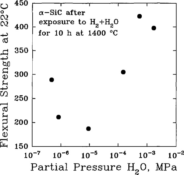
The variation of the room-temperature flexural strength of sintered α-SiC under hydrogen gas with various partial pressures of H2O for 10 h at 1400 °C. (After H. Kim et al., Ceram. Trans. 10, 81–96 (1989).)
Nitrogen-containing environments, Fig. 8, may also result in the active oxidation of SiC [45]. At low gas pressure, SiC may be lost according to:
while at higher pressures, the reaction products may involve solid carbon, silicon nitride, or silicon oxynitride:
Siliconized SiC may also experience a selective attack against the silicon phase according to:
In each of these cases, the strength of the material, Fig. 9, can be affected adversely.
Fig. 8.
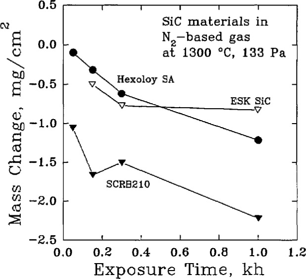
Changes in the mass of commercial silicon carbide materials heated in a nitrogen gas (98.2 vol % N2) at 1300 °C, (After D. P. Butt et al., CAM Newslett. 5 (1), 1 (1991).)
Fig. 9.

The variation of the room-temperature flexural strength of commercial silicon carbide materials after exposure to an endothermic gas (41.1 vol% H2, 37.8 vol% N2, 21.1 vol% CO) at 1300 °C. (After D. P. Butt et al., CAM Newslett. 5 (1), 1 (1991).)
2.3 SiC in Molten Salts
Materials used in industrial flue gases, gas turbine environments, aluminum remelting operations, and coal gasification conditions may be exposed to molten salts such as Na2SO4 and Na2CO3 which promote the deterioration of the silica layer [46]. The dissolution of the silica layer by Na2CO3 is thermo-dynamically favorable and may proceed directly according to the reaction
with a free energy change of −79.9 kJ/mol [47]. In high concentrations, Na2SO4 can be very corrosive also, Fig. 10, for materials such as reaction sintered SiC. However, the direct reactions of Na2SO4 and SiO2
occur with free energy changes of +110 kJ/mol and + 135 kJ/mol, respectively, and therefore are not thermodynamically favorable under equilibrium conditions [48]. While the direct reaction of Na2SO4 and SiC is highly favorable
with free energy change −1855 kJ/mol and —845 kJ/mol, respectively, the silica layer prevents this direct reaction [49]. Instead, two indirect reaction schemes by which Na2SO4 may corrode SiC are considered more probable. The first scheme involves reaction with carbon, either from the aggressive environment or from excess free carbon in the SiC material, to form basic Na2O or Na2S according to
Fig. 10.

The change in the mass of reaction-sintered silicon carbide exposed to various salts at 1000 °C. (After R. E. Tressler et al., J. Am. Coram. Soc. 59 (5–6) 278–279 (1976).)
These compounds then attack the protective silica layer according to
and, hence, lead to the active corrosion, Table 8, of the SiC material [50].
Table 8.
Active corrosion of pressureless sintered SiC under-the linear eorrosion kineties of a salt at 900 °C and 100 kPa (1 atm) of gasa
| Gas | Salt | Corrosion rate (mg · cm−2 · h−1) |
|---|---|---|
| Air | Na2SO4 | −17 |
| Air | Na2SO4 · 5% C | −29 |
| Air | Na2SO4 · 10% C | −28 |
| Air | Na,SO4 · l% NaNO3 | −34 |
| Air | Na2S04 · l% Na2O | −37 |
| Air | Na2SO4 · l% Na2S | −35 |
| Air | Na2SO4 · l% Na2CO3 | −34 |
| Air | Na2SO4 · 5% Na2CO3 | −39 |
| O2 | Na2SO4 · l% Na2CO3 | −18 |
| O2 | Na2S04 · 2% Na2CO3 | −16 |
| O2 | Na2SO4 · 10% Na2CO3 | −17 |
| O2 | Na2CO3 | −45 |
After D. W. MeKee et al„ J. Am. Ceram. Soe. 59 (9–10), 441–444 (1976).
In the second scheme, liquid Na2SO4 dissociates into solid Na2O and gaseous SO3, and the Na2O subsequently interacts with the silica to form a liquid sodium silicate [51]:
It is also possible for a hybrid of these two schemes to occur to form a self-sustaining fluxing mechanism when the hot gaseous environment contains a small partial pressure of SO3. In this case, the Na2SO4 reacts with the free carbon in the substrate to produce Na2O or Na2S which subsequently reacts with the silica layer to form Na2SiO3. The latter product may subsequently react with the SO3 from the atmosphere to produce Na2SO4.
In each scheme, the corrosive pitting of the SiC material results in a degradation of the flexural strength, Table 9, of the material to an extent that depends, Fig. 11, on the severity of the pitting [52].
Table 9.
Four-point bend strength (± 1 standard deviation) of α-SiC (Hexoloy) after exposure to a salt corrodent at 1000 °C for 48 ha
| Gas | Salt | Average strength (MPa) |
|---|---|---|
| Air | None | 409±62 |
| Air | Na2SO4 | 251±45 |
| SO3 | Na2SO4 | 207±72 |
| CO2 | Na2CO3 | 355±70 |
After J. L. Smialek et al., J. Am. Ceram. Soc. 69 (10), 741–752 (1986).
Fig. 11.

The correlation of flexural strength with the corrosion pit depth for a commercial silicon carbide material exposed to various hot salts. (After J. L. Smialek et al., J. Am. Ceram. Soc. 69 (10), 741–752 (1986).)
2.4 SiC in Molten Metals
Corrosion of ceramics by molten metals is not as well described in the literature as corrosion in other environments, although corrosion by molten metals is a concern in the design of heat exchangers for use in aluminum remelt industries, steel reheating furnaces and soaking pits, and other flue gas environments containing metallic species. The primary ceramic being considered for these applications is SiC because of its high thermal conductivity and thermal shock resistance and its potential resistance to corrosion by the molten metals.
The metallic species in the melt principally attack the oxide layer in reactions such as [53]
thereby exposing the SiC to direct corrosion by gaseous halide or other species in the combustion environment and possibly by metal-containing compounds as in the reaction [54]
Sintered SiC, recrystallized SiC, and siliconized SiC were found to have active corrosion rates, Tables 10 and 11, in aluminum remelt and steel soaking pit furnaces, while passive deposits were formed in a steel forge furnace. The mechanical strengths, Table 12, were generally degraded as a result of the increased surface flaws [55].
Table 10.
Surface recession rates for commercial SiC materials exposed to industrial furnace environments. A number greater than zero indicates that a deposit grew on the surfacea
| Furnace environment | Maximum temperature (°C) |
Recession Hexoloy SA |
rate NC400 |
(mm/yr) NC430 |
|---|---|---|---|---|
| Aluminum remelt No. 1 | 1040 | −0.28 | −0.14 | −0.42 |
| Aluminum remelt No. 2 | 1150 | −3.78 | −1.89 | |
| Steel soaking pit No. 1 | 925 | −0.05 | −0.03 | −0.17 |
| Steel soaking pit No. 2 | 1250 | −3.53 | −4.32 | |
| Steel reheat | 1100 | −0.05 | −0.69 | |
| Forge | 1175 | + 0.05 | + 0.31 | −0.13 |
After J. I. Federer et al., Adv. Ceram. 14, 315–334 (1985).
Table 11.
Surface recession rates for various SiC materials exposed to industrial furnace environmentsa
| Furnace environment | Temperature range (°C) | Recession rate (mm/yr) | Hot pressed |
||
|---|---|---|---|---|---|
| Hexoloy SA |
CS101 | CS101K | |||
| Aluminum remelt No. 1 | 750–1250 | −2.8 | −7.15 | −7.00 | −7.00 |
| Aluminum remelt No. 2 | 750–1200 | −2.07 | −1.94 | −1.12 | |
| Steel soaking pit | 1150–1175 | −0.4 | −0.90 | −0.15 | −0.15 |
After J. I. Federer, Ceram. Trans. 10, 425–443 (1989).
Table 12.
Room temperature fracture strength of Hexoloy SA determined by c-ring tests after exposure to industrial furnace environments
| Furnace environment | Number of samples | Average strength (MPa) |
|---|---|---|
| aAir | 18 | 280±50 |
| aAluminum remelt | 12 | 243±23 |
| bAluminum remelt No. 1 | 12 | 213±39 |
| bSteel soaking pit | 11 | 246±56 |
| bSteel reheat | 12 | 221±34 |
| bForge | 9 | 286±43 |
After J. Luyten et al., High Temperature Corrosion of Technical Ceramics (1900) pp. 161–168.
After J. I. Federer et al., Adv. Ceram. 14, 315–334 (1985).
2.5 SiC in Complex Environments
Heat exchangers in coal combustion or coal gasification environments may be exposed to a combination of hot gases, Table 13, and molten slags, Table 14, simultaneously. Such complex environments increase the number of reaction paths that may be involved in the degradation of the protective silica layer and the active corrosion of the substrate. As should be expected, the experimental results produced in such environments are difficult to interpret precisely and may result in apparent contradictions. For example, compared to silicon carbide, alumina has been found to be both less resistant [56] and more resistant [57] to corrosion in slags nominally characterized as acidic.1 The significance of this apparent contradiction is not that the results differ, but that a more precise characterization of the envirionment and the materials is needed along with consideration of the possible transport phenomena, such as fluxing, that can affect the overall nature of the corrosive process. In general, it can be noted that the corrosion of structural ceramics in complex environments tends to result in a net loss of material, Table 15, and the extent of the loss varies with the relative amount of basic and acidic components in the slag [58,59]. Acidic slags typically produce recession rates on the order of 1 mm/yr for silicon carbide at high temperature, while the recession rates from basic slags are on the order of 10–100 mm/yr.
Table 13.
Simulated gas composition for a medium-energy coal gasification environmenta
| Gas: | H2 | CO | CO2 | N2 | H2S | H2O |
| Vol. % | 30 | 44 | 10 | 1.4 | 0.6 | 14 |
After T. E. Easier et al., in High Temperature Corrosion in Energy Systems (1985) pp. 269–280.
Table 14.
Composition (percent by weight) of various coal slags
| Component | Slag 1a | Slag 2b | Slag 3c | Slag 4c | Slag 5d | Slag 6d |
|---|---|---|---|---|---|---|
| SiO2 | 45.77 | 50.80 | 50 | 30 | 54 | 56 |
| Fe2O3 | 10.72 | 16.28 | 25 | 15 | 21 | 4 |
| Al2O3 | 14.17 | 23.93 | 20 | 10 | 19 | 31 |
| CaO | 18.75 | 2.72 | 5 | 25 | 0.1 | 0.5 |
| MgO | 7.08 | 0.72 | 20 | 0.9 | 0.8 | |
| NiO | 0.01 | |||||
| SO3 | 0.055 | 1.65 | ||||
| P2O5 | 0.51 | 0.27 | ||||
| Na2O | 1.10 | 0.47 | 0.6 | 2.5 | ||
| K2O | 0.52 | 1.60 | 1.7 | 2.6 | ||
| TiO2 | 0.27 | 0.62 | 1.3 | 0.8 | ||
| SrO + BaO | 0.16 | |||||
| V2O5 | 0.03 | |||||
| Base/Acid | 0.63 | 0.29 | 0.43 | 1.5 | 0.33 | 0.12 |
After M. K. Ferber et al., J. Am. Ceram. Soe. 68 (4), 191–197
(1985).
After M. K. Ferber et al., Ceram. Bull. 62 (2), 236–243 (1983).
After T. E. Easier et al., in High Temperature Corrosion in Energy Systems (1985) pp. 269–280.
After P. F. Becher, J. Matls. Sei. 19, 2805–2814 (1984).
Table 15.
Corrosion rates for various commercial grades of SiC exposed to various environments for 200 h at 1250 °C. (See Table 14 for slag compositions)a
| Material | Condition | No slag (air) (μg · cm−2 · h−1) | Acidic slag (Slag 3) (μg · cm−2 · h−1) | Basic slag (Slag 4) (μg · cm−2 · h−1) |
|---|---|---|---|---|
| Hexoloy SA | Slip-cast | + 0.7 | −174 | −657 |
| Hexoloy SA | Extruded | −0.4 | − 50 | −412 |
| NC430 | Slip-cast | +1.6 | −117 | −412 |
| NC430 | Extruded | + 5.7 | − 50 | −136 |
After T. E. Easier et al., in High Temperature Corrosion in Energy Systems (1985) pp. 269–280.
Part of the dependence on the acidity or basicity of the slag may result from the order of magnitude difference in the viscosities of these slags at high operating temperature. The viscosity of an acidic slag is estimated to be approximately 60 Pa · s (600 poise), while being only 5 Pa · s (50 poise) for a basic slag [60]. The lower viscosity of the basic slag should be more conducive to the diffusion of the reactant and product species and thus to a more extensive material loss.
Specific chemical contributions to the differences between acidic and basic slags are thought to result from the greater presence of iron and calcium compounds in the basic slags. CaO may interact with the silica layer to form calcium silicate compounds, thereby reducing the effectiveness of the silica layer [61]. Localized, active corrosion of the SiC may occur when the iron compounds react directly with the SiC subsrate to form iron silicides with an effective reaction of the form [62]:
This localized corrosion mechanism is thought to be important particularly for a slag thickness of 100 μm or greater and a temperature of 1250 °C or higher. Under these conditions, bubble formations from the evolution of gaseous SiO and CO may disrupt the silica layer, thereby providing the means for a direct reaction between the slag and the substrate.
Corrosion affects the lifetime of a material under in-service conditions not only through the loss of material, but also through the variation of the strength of the material. Corrosion increases the population of surface flaws which degrades the strength of the material and reduces its lifetime by increasing the probability of fracture under a mechanical or thermally induced stress. The strengths of SiC materials at elevated temperature were measured by C-ring tests, Table 16 [63], and four-point bend tests, Table 17 [64], after exposing the materials to coal slags at various temperatures for various amounts of time. From these results, it may be readily inferred that the degradation of the strength of the material due to a temperature rise is compounded by oxidation, and both of these effects are significantly compounded by reaction with the slag. It is also significant that corrosion pits were cited as the primary failure sites of the exposed samples in both the C-ring tests and the four-point bend tests.
Table 16.
High-temperature c-ring fracture strength of Hexoloy SA SiC after exposure to various environments. (See Table 14 for the slag composition.)a
| Environment | Temperature (°C) | Exposure time (h) | Fracture strength (MPa) |
|---|---|---|---|
| Air | 1200 | 0 | 397±7.6 |
| Air | 1200 | 24 | 375±6.6 |
| Air | 1300 | 0 | 354±8.9 |
| Air | 1300 | 24 | 361±9.3 |
| Slag 1 | 1200 | 24 | 335±9.3 |
| Slag 1 | 1300 | 24 | 285±3.6 |
After M. K. Ferber et al., J. Am. Ceram. Soe. 68 (4), 191–197 (1985).
Table 17.
Four-point flexural strengths of silicon carbide materials after exposure to various environments. Materials were exposed to the slag for 1150 °C for 350 h. (See Table 14 for the composition of the slag.)a
| Material | Environment | Temperature | Flexural strength (MPa) |
|---|---|---|---|
| NC203 | Air | 22 | 707 |
| NC203 | Air | 1000 | 621 |
| NC203 | Air | 1200 | 550 |
| NC203 | Air | 1300 | 493 |
| NC203 | Slag 6 | 22 | 386 |
| NC203 | Slag 6 | 1000 | 414 |
| NC203 | Slag 6 | 1150 | 429 |
| NC203 | Slag 6 | 1300 | 371 |
| Hexoloy SA | Air | 22 | 407 |
| Hexoloy SA | Air | 1000 | 464 |
| Hexoloy SA | Air | 1300 | 471 |
| Hexoloy SA | Slag 6 | 22 | 286 |
| Hexoloy SA | Slag 6 | 1150 | 343 |
| Hexoloy SA | Slag 6 | 1300 | 429 |
| KT | Air | 22 | 200 |
| KT | Slag 6 | 22 | 186 |
| KT | Slag 6 | 1150 | 221 |
| KT | Slag 6 | 1300 | 214 |
After P. F. Bccher, J. Matls. Sci. 19, 2805–2814 (1984).
3. Si3N4
Silicon nitride exists in two crystallographic phases, denoted α-Si3N4 and β-Si3N4 [65]. The α-Si3N4 phase transforms to the β-Si3N4 form at approximately 1500 °C. Silicon nitride powders may be prepared by several different methods. The direct nitridation of silicon powder produces silicon nitride by the reaction
The carbothermic reduction of silica may also be used according to
Amorphous silicon nitride with very fine particle sizes can be produced by vapor phase methods using reactions such as
Silicon nitride powders can be processed by a variety of methods to produce bulk materials for structural applications. Common methods include hot pressing, sintering, hot isostatic pressing, and sintering of reaction-bonded compacts [66]. Sintering aids such as MgO and Y2O3 are usually used with all of the methods to produce high density products. In hot pressing, uniaxial stresses on the order of 15–30 MPa may be applied to the powder for several hours at temperatures in the range 1650 to 1850 °C. Pressureless sintering, in contrast, is conducted in a nitrogen atmosphere of approximately 0.1 MPa in the temperature range 1600 to 1800 °C. In both cases, boron nitride may be used for various purposes in containing or manipulating the product material with the result that the surface of the product may have a small boron nitride contamination. The final product is generally a polycrystalline material consisting primarily of elongated, fiber-like, β-Si3N4 grains and a secondary, intergranular phase that may be either glassy MgO or crystalline Y2O3. When MgO is used as an additive in quantities greater than 5 wt. %, crystalline Mg2SiO4 may also be present. For reaction-bonded silicon nitride fired in a lower temperature range, 1150 to 1400 °C, the final product may consist predominantly of α-Si3N4 grains with a lower bulk density and a significantly larger porosity, on the order of 10%–30%.
3.1 Oxidation of Si3N4
The oxidation of silicon nitride is a complex process that depends significantly on the sintering aids and the impurities in the material [67]. The primary protective scale is silica which may be formed directly from the reaction of silicon nitride and oxygen:
This reaction may be most significant during the initial oxidation of the substrate. Subsequently, multistep reaction sequences may be more important.
In the case of chemical vapor deposited (CVD) silicon nitride without sintering aids [68], the formation of a duplex oxide scale has been reported. The scale was found to consist of an outer layer of silica and an inner layer of silicon oxynitride. The oxidation process in this case could be described by two reaction steps. First, oxygen diffused through the silica layer to the silicon oxynitride layer where part of the oxygen reacted to form additional silica according to:
The unreacted oxygen continued to diffuse to the substrate material where additional silicon oxynitride was formed:
Diffusion through the silicon oxynitride layer was identified as the rate-controlling process because the molecular oxygen diffusivity, Table 18, was significantly smaller for Si2N2O than for SiO2. The overall oxidation process, though, followed parabolic kinetics,
in which the square of the scale thickness is proportional to the time of exposure, with a parabolic rate constant, kp, of 66 nm2/min.
Table 18.
Molecular oxygen diffusivitics of silica and silicon oxynitridea
| Material | Temperature (°C) | Diffusivity (10−8 cm2/s) |
|---|---|---|
| SiO2 | 1100 | 1.42 |
| SiO2 | 1200 | 2.78 |
| SiO2 | 1300 | 5.00 |
| SiO2 | 1400 | 8.37 |
| Si2N2O | 1200 | 0.00240 |
| Si2N2O | 1300 | 0.00927 |
| Si2N2O | 1400 | 0.110 |
After R. E. Tressler et al., in High Temperature Corrosion of Technical Ceramics (1990), pp. 69–89.
When sintering aids or impurities have been present, the composition of the scale has been found to be more complex. For hot-pressed Si3N4 containing MgO and CaO as additives, the scale consisted of glassy SiO2, in which crystalline α-cristobalite also formed, plus magnesium silicates and magnesium-calcium silicates [69]. A similar study analyzed the composition of the scale, Table 19, and found that MgSiO3 could be clearly identified as a principal component of the scale [70]. Other compounds, while evidently present, could not be identified conclusively. The oxidation kinetics relation was parabolic, Fig. 12, as has been found to be common for most MgO-containing silicon nitrides [71], with an activation energy of approximately 440 kJ/mol [72].
Table 19.
Composition of the oxide scale formed on hot-pressed HS-130a
| Temperature (°C) | Exposure time (h) | O2 Pressurte (kPa) | Si (wt%) | Mg (wt%) | O (wt%) |
|---|---|---|---|---|---|
| 1300 | 24 | 80 | 27.4 ± 2 | 17.37 ± 2.8 | 55.2 |
| 1350 | 194 | 20 | 28.1 ± 0.8 | 16.8 ± 0.5 | 55.12 |
| 1400 | 24 | 10 | 28.0 ± 0.3 | 23.15 ± 0.8 | 48.89 |
| 1400 | 24 | 20 | 29.0 ± 3.5 | 22.0 ± 4.0 | 49.0 |
| 1400 | 24 | 40 | 27.9 ± 0.5 | 21.61 ± 0.8 | 50.53 |
| 1400 | 24 | 80 | 27.9 ± 0.5 | 21.96 ± 0.5 | 50.15 |
| 1450 | 21 | 20 | 30.0 ± 0.6 | 26.68 ± 1.5 | 46.26 |
| 1475 | 24 | 20 | 28.6 ± 0.5 | 21.9 ± 1.5 | 49.49 |
| 1500 | 24 | 20 | 39 | 10 | 51 |
After W. C. Tripp et al., J. Am. Ceram. Soc. 59 (9–10), 399–403 (1976).
Fig. 12.

The oxidation of a commercial silicon nitride material in dry oxygen showing parabolic oxidation kinetics. (After W. C. Trip et. al., J. Am. Ceram. Soc. 59 (9–10), 399–403 (1976).
The oxide scale formed on sintered silicon nitride containing yttria as a major sintering aid has been found to differ both substantially and morphologically from the scale on Si3N4 prepared either by hot pressing with MgO or by the CVD technique [73]. The scale itself was found to be a layered structure in which each layer had an outer region of crystalline silica, an intermediate glassy region, and an inner thin layer of Y2Si2O7. The glassy region was porous, often containing large bubble formations that most likely resulted from the evolution of N2 gas during oxynitride formation. Thin layers of Y2Si2O7 were also found at the interface between the substrate and the scale, and at the outer surface of the scale.
It was suggested that the morphology of the scale had a direct effect on the apparent oxidation kinetics of the material. Initially, the scale growth was logarithmic rather than parabolic, such that
for constants k1 and k2. It was reasoned that such a relation would be appropriate if the effective cross section through which diffusion could occur diminished with time, as might have occurred when gas bubbles grew in the scale. Subsequently, when a sufficient cristobalite layer had formed, the slow diffusion rate through that layer would be rate-controlling, and the kinetic relation would become parabolic. A behavior consistent with this scheme was also observed in a study using silicon nitride sintered with Y2O3 and Fe2O3 [74]. In that work, the kinetics relation was described as being asymptotically parabolic with an apparent activation energy of 470 kJ/mol.
At sufficiently low oxygen partial pressure, the passive oxidation of silicon nitride may change to active oxidation [75]. The temperature at which this transition occurs for a given oxygen pressure, Table 20, increases with increasing oxygen pressure [76].
Table 20.
Active-to-passive transition temperature, Tap, for hot pressed HS-130 and sintered 6Y-14 silicon nitride at various values of the partial pressure of oxygen, P(O2).a
| Material | Flow rate (em3/s) | P(O2) (Pa) | Tap (°C) |
|---|---|---|---|
| HS-130 | 0.56 | 7.1 | 1366 |
| HS-130 | 0.56 | 27.4 | 1436 |
| HS-130 | 0.56 | 205.5 | 1520 |
| 6Y-14 | 0.56 | 7.0 | 1365 |
| 6Y-14 | 0.56 | 28.5 | 1446 |
| 6Y-14 | 0.56 | 111.0 | 1480 |
After W. L. Vaughn et al., J. Am. Ceram. Soc. 73 (6), 1540–1543 (1990).
The strength of both sintered and hot pressed silicon nitride materials have been found to decrease for oxidation times of one hour or longer [77]. A brief increase in strength was noted for very short oxidation times, approximately 30 min, which was thought to be due to the blunting of crack tips. For longer times, Table 21, the oxidation of the material resulted in the generation of new flaws that caused the average strength to decrease. Oxidizing the two materials under static load, however, resulted in distinct behaviors. The sintered material had an increase in strength, while the hot-pressed material suffered a decrease in strength.
Table 21.
The room temperature Weibull paramerters for sintered SNW-1000 and hot-pressed NCX-34 silicon nitride ceramics after oxidation at 1370 °C in air under various loads. σ0 = Weibull characteristic strength, m = WeibuII modulus, and R2 = correlation coefficienta
| Material | Load during oxidation (MPa) | Oxidation time (h) | Number of samples (MPa) | σ0 | m | R2 |
|---|---|---|---|---|---|---|
| SNW-1000 | 0 | 0 | 50 | 300 | 8.2 | 0.98 |
| SNW-1000 | 0 | 0.5 | 10 | 325 | 7.7 | 0.97 |
| SNW-1000 | 0 | 1 | 53 | 290 | 10.9 | 0.94 |
| SNW-1000 | 0 | 12 | 11 | 275 | 17.2 | 0.97 |
| SNW-1000 | 0 | 20 | 11 | 215 | 8.3 | 0.90 |
| SNW-1000 | 0 | 50 | 10 | 225 | 19.6 | 0.98 |
| SNW-1000 | 23 | 1 | 15 | 390 | 10.2 | 0.99 |
| SNW-1000 | 45 | 1 | 15 | 295 | 7.0 | 0.97 |
| NCX-34 | 0 | 0.5 | 10 | 555 | 7.0 | 0.96 |
| NCX-34 | 0 | 1 | 54 | 575 | 14.1 | 0.96 |
| NCX-34 | 0 | 12 | 11 | 400 | 7.0 | 0.92 |
| NCX-34 | 0 | 20 | 12 | 500 | 14.3 | 0.96 |
| NCX-34 | 0 | 50 | 12 | 435 | 7.6 | 0.94 |
| NCX-34 | 45 | 1 | 14 | 490 | 9.7 | 0.93 |
| NCX-34 | 158 | 1 | 13 | 385 | 7.9 | 0.93 |
After T. E. Easier et al., J. Am. Ceram. Soc. 65 (6), 317–320 (1982).
3.2 Si3N4 in Hot Gases
The passive oxidation of hot-pressed silicon nitride has been found to be enhanced by water vapor in oxygen atmospheres [78], with the parabolic rate constant, Table 22, being larger than for dry oxygen. The activation energy for oxidation was 488 ± 30 kJ/mol in wet oxygen and 375 ± 25 kJ/mol in dry oxygen.
Table 22.
Parabolic rate parameter, Kp, for the oxidation of hot-pressed HS-130 silicon nitride in O2 with a partial pressure of water vapor of 3.3 kPa (0.033 atm)a
| Temperature (°C) | log Kp (g2•cm−4•s−1) |
|---|---|
| 1200 | −12.6 |
| 1260 | −12.0 |
| 1315 | −11.3 |
| 1370 | −10.8 |
After S. C. Singhal, J. Am. Ceram. Soc. 59 (1–2) 81–82 (1976).
The presence of gaseous H2O in H2 gaseous environments has been found to cause an active oxidation of Si3N4 according to [79]:
Under these conditions, the average flexural strength of the material, Table 23, decreased. When the partial pressure of H2O was greater than about 10 Pa, a protective silicate layer may have formed as a result of a reaction between the gaseous reaction product, SiO, and the sintering aid, Y2O3. Concurrently, the flexural strength of the material increased.
Table 23.
Room-temperature flexural strength, σ, of hot isostatically pressed AY6 silicon nitride after exposure at 1400 °C for 10 h in H2 atmospheres with various partial pressures P(H2O) of water vapora
| P(H2O) (Pa) | σ (MPa) |
|---|---|
| 0.26 | 580 ± 35 |
| 0.45 | 525 ± 60 |
| 3.6 | 515 ± 30 |
| 20 | 460 ± 40 |
| 100 | 690 ± 60 |
| 520 | 800 ± 80 |
After H. Kim et al., Ceramic Transactions 10, 81–96 (1989).
3.3 Si3N4 in Molten Salts
The corrosion of silicon nitride by molten salts has been found to occur in three stages. For sodium carbonate on reaction-bonded Si3N4, the first stage is a very brief process, lasting only minutes, during which sodium silicate is formed. The second stage follows diffusion-limited parabolic reaction kinetics resulting from the inward diffusion of molecular oxygen to the silicon nitride surface where the subsequent reaction forms silica. The silica material, though, partially dissolves into the silicate glass until a saturation limit is reached. Thereafter, oxidation produces a growing silica layer. Oxygen diffusion through this layer is very slow, and becomes the rate limiting step for the third stage of the corrosion process [80].
A similar study on hot isostatically pressed reaction-bonded Si3N4 obtained very similar results [81]. The brief first stage was found to be a period of weight loss controlled by two reactions. In the first, gaseous oxygen reacted with the silicon nitride to form a solid silica layer according to:
Subsequently, the silica dissolved in the molten salt layer to form a liquid sodium silicate:
The first stage process was completed after approximately 5 min after which weight gain occurred primarily due to the formation of silica.
Corrosion of silicon nitride by sodium sulfate was found to have a similar corrosion process consisting, however, of only two stages, an initial lengthy period of slow weight loss followed by a process of slow weight gain. The weight loss appeared to be mostly the result of the vaporization of the Na2SO4. The primary reaction sequence for corrosion was a coupled oxidation-dissolution process such that:
Silica formation and dissolution proceeded with the silica layer growing at a rate that was faster than what was expected for normal oxidation. Eventually, the silica layer became sufficiently thick that further oxidation of the silicon nitride substrate was limited by the slow diffusion of oxygen through the silica layer.
3.4 Si3N4 in Molten Metals
Hot pressed silicon nitride materials, with either Y2O3 or MgO as sintering aids, have been exposed to the flue gas of an aluminum remelting furnace in which the flue gas consisted mainly of CO2, CO, O2, and H2O, plus small amounts of Cl, F, SO2, SO3, NO, and NO2. After exposure, the silicon nitride specimens were found to be coated with a vitreous deposit in which β-Si3N4, Si, and Al2O3 were found [83]. The Si3N4 material apparently diffused or dissolved from the substrate and was absorbed into the deposit, while the Si and A12O3 were derived from the aluminum melt. The deposit also showed evidence of trapped gas bubbles, and some depletion of the sintering aid components was found in the surface region of the substrate material adjacent to the vitreous deposit. The latter result indicated that it was primarily the inter-granular phases that were corroded. Specimens with MgO as the sintering aid appearred to be less resistent to corrosion than specimens with Y2O3 as the sintering aid, as was reflected in the variations of the flexural strengths of the materials, Table 24. While both materials had significantly reduced flexural strengths, the residual strength of Si3N4(Y2O3) was nearly twice that of Si3N4(MgO).
Table 24.
Four-point bend strengths of hot-pressed silicon nitride materials after exposure to an aluminum remelting furnacea
| Sintering Aid | Exposure time (h) | Number of samples | Average strength (MPa) |
|---|---|---|---|
| Y2O3 | 0 | 20 | 610±39 |
| Y2O3 | 100 | 8 | 437±62 |
| MgO | 0 | 10 | 610±54 |
| MgO | 100 | 8 | 282±38 |
After J. Luyten et al., High Temperature Corrosion of Technical Ceramics (1990) pp. 161–168 (1990).
3.5 Si3N4 in Complex Environments
An extensive penetration of coal slag into hot pressed NCX-34 silicon nitride was found as a result of corrosion in simulated coal combustion environments (slags 5 and 6 in Table 14) [84]. This material had WC and β-Y5Si3O12N as minor phases in the material. It was noted that the oxidation of Y5Si3O12N to form Y2SiO5, cristobalite SiO2, or RY5Si6O2, where R may be H, Na, Mn, Fe, Al, Th, or Zr, would occur with a large increase in molar volume. The resulting tensile stress could cause microcracking and thus would promote slag penetration and the formation of subsurface pits. These microcracks and pits were cited as being responsible for the strength degradation, Table 25, observed in these environments. When the corroded layer of the surface was removed by diamond grinding, the strength of the material returned to approximately 95% of its original, as-received value. Thus the strengh-reducing defects were limited to the surface of the specimens and did not involve internal compositional changes in the substrate.
Table 25.
Room-temperature four-point flexural strengths of silicon nitride materials after exposure to various environments. (See Table 14 for the composition of the slag.)a
| Material | Environment | Temperature (°C) |
Exposure time (h) |
Flexural strength (MPa) |
|---|---|---|---|---|
| NC-132 | Air | 22 | 0 | 850 |
| NC-132 | Slag 5 | 1220 | 500 | 325 |
| NC-132 | Slag 6 | 1150 | 350 | 430 |
| NCX-34 | Air | 22 | 0 | 810 |
| NCX-34 | Slag 5 | 1220 | 500 | 300 |
| NCX-34 | Slag 6 | 1150 | 350 | 325 |
After P. F. Becher, J. Matls. Sci. 19, 2805–2814 (1984).
4. Coating Systems
The primary corrosion resistance of both silicon carbide and silicon nitride results from the oxide layer formed on the surface of the material. It is reasonable, therefore, to consider the possibility of enhancing the corrosion resistance of these materials by modifying their surfaces with specially prepared oxide coatings. For such coatings, there would be chemical, thermal, and mechanical requirements beyond the need to resist corrosion by combustion gases, slag, and ash. The coating and substrate materials would need to be well bonded but otherwise would have a low rate of subsequent reaction, and their coefficients of thermal expansion would need to be compatible to prevent thermally induced stresses and subsequent cracking. The coating also would need to have adequate toughness and thermal shock resistance, as well as a sufficiently high thermal conductivity, so that the performance of the system would not be affected adversely.
Initial insight into the selection of candidate coating materials may be derived from a consideration of the phase equilibria relations between the slag and ash constituents and the candidate oxide coatings. For slagging conditions in particular, the major slag constituents are silica, alumina, and iron oxide; hence, coatings of these same oxides would be expected to be dissolved by the slag. Other slag constituents such as alkali and rare earth oxides could also react with these coatings to produce lower melting point compositions which would degrade the performance of the coatings. Consequently, silica, alumina, and iron oxide would not be expected to be well suited as protective coatings in these coal-fueled applications.
Little work appears to have been reported on the use of ceramic coatings on ceramics. However, preliminary indications of the potential for such coatings may be gained from current studies of refractory oxide coatings and from ceramic coatings on metal alloys in turbine engines.
Refractory oxide coatings have been used successfully in the radiant heater sections of pulverized coal-fueled boilers to protect low-alloy water walls. In these slagging applications, a layer of solidified slag underlies the molten deposit and limits the solution of the refractory coating into the slag deposit. General summaries of research on the behavior of refractory oxides in coal gasification systems indicate that alumina refractories [85] might be suitable for use in dry ash systems to 1100 °C and that magnesia-chromia refractories [86] might be useful in slagging systems at temperatures of 1500 °C. However, it should be noted that these applications exhibit lower oxygen partial pressures and higher water partial pressures than would be expected in combustion systems, and the refractories examined in these studies were in brick or castable forms with significant amounts of other phases present.
There is a significant body of research on the stability of oxide-forming elements in alloys in coal gasification and combustion applications. Much of this research has been conducted with a focus on the propensity for sulfidation [87]. The results have clarified the regimes of oxygen, sulfur [88], and chlorine [89] partial pressures in which protective oxides are stable and have helped to understand alloy corrosion mechanisms [90].
Table 26 shows the lower partial pressure limits of stability for several oxides in oxygen and sulfur, The values shown in the table are many orders of magnitude lower than any value that might be expected to be encountered in combustion systems. As a result, none of these oxides would have an intrinsic problem in terms of stability.
Table 26.
The partial pressures of oxygen, , above which selected oxides are stable. The concurrent partial pressure of sulfur, PS, is also showna
| Oxide | T = 1150 K log10 ( ) (P in Pa) | (877 °C) log10(Ps) (P in Pa) | T=1450 K log10 ( ) (P in Pa) | (1177 °C) log10 (PS) (P in Pa) |
|---|---|---|---|---|
| SiO2 | −27 | 0 | −18 | 2 |
| Al2O3 | −34 | 13 | −24 | − 8 |
| ZrO2 | −35 | −17 | −25 | −11 |
| Ce2O3 | −40 | −31 | −28 | −21 |
| Cr2O3 | −20 | − 7 | −13 | − 3 |
| MgO | −39 | −23 | −26 | −15 |
After E. A. Gulbranson and G. H. Meier, DOE/FE/13547-01, UC-90h (May 1980).
Among the materials listed in Table 26, the relatively high coefficient of thermal expansion of zirconia has encouraged its use as a thermal barrier coating on metallic gas turbine components. This application has required investigation of the corrosion of zirconia-based coatings in combustion environments. Typically, low velocity burner rig tests have been conducted on compositionally graded coatings [91]. In these experiments, corrosive alkali sulfates and sulfates with vanadium were deposited on zirconia containing 8% yttria as a stabilizing oxide. No significant reaction of zirconia with sodium sulfate was noted. However, the addition of vanadium and magnesium, at the level of 50 parts per million, was shown to foster corrosive reactions and the destabilization of the zirconia. Significantly, the porosity of the coating also was shown to foster coating failures due to the penetration of liquid sodium sulfate into the coating [92]. Under thermal cycling, the liquid sodium sulfate was thought to have frozen and expanded, thereby mechanically opening cracks in the coating. Failure in these experiments, Table 27, was determined as the onset of cracking or spallation. Coating lifetimes greater than 500 h were reported.
Table 27.
Burner rig corrosion test results of thermal barrier coatingsa
| Coating | Intermediate layer | Overcoat | Time to failure (h) |
|---|---|---|---|
| PS ZrO2 | NiCrAlY Bond Coat | Pt | 242 |
| PS ZrO2 | NiCrAlY Bond Coat | AlPt | >500 |
| PS ZrO2 | NiCrAlY Bond Coat + ZrO2/NiCrAiY | Pt | >500 |
| PS ZrO2 | NiCrAlY Bond Coat + ZrO2/NiCrAlY | AlPt | 500 |
| PVD ZrO2 | none | none | 22–70 |
C. A. Anderson et al., NASA Report CR-65919 (February, 1982).
- PS = Plasma spray
- Bond Coat = 127 μm thick
- ZrO2 = 380 μm thick
- PVD = Electron Beam Physical Vapor Deposition
- ZrO2/NiCrAlY = 50 vol% ZrO2−8Y2O3 + 50 vol% NiCrAlY
- Pt: 31 μm thick sputter deposited
- AlPt: 14 μm thick sputter deposited
- Fuel: No. 2 Distillate with:
Element Na Mg Cl K Ca S Amount (ppm) 100 10 180 3 4 2 - Nominal gas temperature = 1204 °C
- Maximum metal temperature = 843 °C
- Test duration=500 h
- Cycle = 55 min. heating + 5 min. air cooling
Concern over the role of vanadium in the deterioration of stabilized zirconia coatings has resulted in research on the reactivity of indium oxide, scandium oxide, yttria, and magnesia stabilizers. Thermogravimetric analyses of these oxides in molten sodium vanidate equilibrated in an SO3 environment has shown indium oxide and scandium oxide to be more resistant to attack than the conventional stabilizers, yttria and magnesia [93].
Finally, attempts are being made to improve the compatibility of ceramic coatings and metal substrates. The effort is specifically designed to reduce the thermal stresses caused by the different amounts of thermal expansion experienced by metals and ceramics. The approach being taken is to use intermediate layers of materials to provide a gradual transition in the coefficient of thermal expansion across the interface region [94]. For metallic substrates, the intermediate layers typically have consisted of mixed ceramic and metallic compositions which unfortunately provides an opportunity for corrosion to occur beneath the ceramic over-layer. At the present time, therefore, the use of ceramic coatings metallic interlayers does not appear to offer a significant advantage for coal-fueled applications.
5. Conclusion
Significant progress towards a comprehensive understanding of the oxidation of both silicon carbide and silicon nitride has been made over the past several decades. Models have been advanced to account for the quantitative effects of competing chemical reactions, required mass transport mechanisms, and changes in surface and microstructural morphologies. In contrast, models describing the corrosion of these materials in complex environments are considerably more speculative. Few studies have been made to isolate the effects of specific components of either the complex atmosphere or the material. Most recent studies involving complex environments have been focused on the more immediate concerns of engineering design, viz., does the given material have adequate corrosion resistance for the given design objective? Important clues towards the development of better materials can be provided by such studies, particularly when analyses of the compositions of the starting materials and environments are given along with the compositions of the reaction products. However, the development of detailed models must rely on known results of specific interactions. Consequently, much of the understanding of corrosion in complex environments is based on detailed studies of oxidation or of corrosion in simplified environments.
The silica layer, for example, that develops at the surface of the SiC or Si3N4 substrate, is known to play a key, multifaceted role in the corrosion resistance of both materials. The frequently observed parabolic corrosion kinetics may be directly related to the diffusion of oxygen through an oxide layer, but there are numerous reaction sequences that can contribute to that result.
For silicon carbide, silica forms a protective barrier that prevents the direct reaction of the substrate with an attacking species. The diffusion of oxygen through the silica results in parabolic reaction kinetics. The oxide barrier, however, may be sacrificial in the sense that the silica itself may be dissolved in a molten deposit. Replenishment of the silica layer then depends on the diffusion of oxygen to the substrate where additional silica can be formed by the oxidation of the substrate. If the attacking deposit or the silica layer impedes the flow of oxygen to the substrate, such that the partial pressure of oxygen is very low, then the silica itself may react directly with the substrate causing both reactants to be diminished.
For silicon nitride, the oxidation of the substrate forms silicon oxynitride which subsequently oxidizes to form silica. In this case, parabolic reaction kinetics are still observed, but the layer of silicon oxynitride may control the oxygen diffusion rate.
The dominant reaction sequence at any time may be strongly influenced by the chemical species in the attacking atmosphere and by the impurities, sintering aids, grain boundary phases, and porosity of the substrate material, as well as the immediate reaction history. Impurities such as carbon, for example, may cause an acidic slag to behave more like a basic slag with respect to corrosion of silicon carbide. For silicon nitride, sintering aids such as MgO and CaO may add magnesium-calcium silicate components to the oxide layer and may influence the crystalline or glassy nature of the oxide. Additional quantitative sudies are needed to investigate these effects in greater detail.
In the context of designing components for use in corrosive environments, there are two primary concerns regarding the selection of a material: the survival of the material, expressed as the recession rate of the surface, and the mechanical strength of the component. The corrosion rates for ceramics can be relatively small, and, as a result, the recession rates may be tolerable. Recession rates of SiC on the order of 1 mm/yr in acidic slag and 10–100 mm/yr in basic slags are possible. However, surface pitting and the overall increase in the surface flaw populations generally degrade the strength of the material and can reduce its average mechanical lifetime even when the recession rate is small. While some combinations of material and environment may produce a short-term strength enhancement resulting from the healing of surface defects, long-term corrosion generally tends to decrease the strength of the material as the severity of the surface pitting increases. An understanding of the interplay of the time-dependent chemical and mechanical effects and consequences has yet to be established.
There are several critical issues that have yet to be examined. Prominent among these issues is long-term corrosion. Most studies report short-term results that span only a few tens of hours, and results with exposure times on the order of 1000 h are scarce. Long-term data are particularly needed to study possible time-dependent phenomena such as break-away corrosion and the potential for lifetime-limiting effects such as environmentally enhanced creep phenomena.
Of equal importance is the need for systematic studies of corrosion in environments that are well characterized chemically and thermally. Studies conducted in industrial furnaces are valuable proof tests, but the results are often difficult to interpret because the precise composition of the environment is unknown and both the composition and the temperature distribution may vary over the course of the study.
In conjunction with these tests, mechanical properties need to be measured in situ at elevated temperature. Secondary or grain boundary constituents, impurities, and reaction products can be liquids at the temperatures of interest. Measurements at room temperature do not properly reflect the consequences of these phases, nor do they account for environmentally assisted fracture effects.
Lastly, while it has been noted that the corrosion behavior of various types of silicon carbide and silicon nitride have been examined in many environments, little research has focused on the role of ceramic coatings in protecting silicon-based materials. It may be possible to enhance the corrosion resistance of silicon-based ceramics by the use specially designed oxide coatings. Coatings of either the overlay type, which may be applied by plasma spraying, or surface modified materials offer the potential to develop surface layers more resistant to reaction with alkali or slag deposits than native silica. Consideration of previous experience with coatings for refractory ceramics and metal alloys suggests that zirconia stabilized with indium oxide or scandium oxide might provide an effective coating for silicon-based ceramics. However, the extent of corrosion may depend on the specific slag and ash deposit compositions, and the degree of protection may depend significantly on the capacity of the coating to resist spallation and cracking. Measurements of the thermal and mechanical properties of such coatings, along with studies of potential problems associated with the porosity of the coating, would have to be made.
Acknowledgments
The authors thank the Pittsburgh Energy Technology Center for their support of this work under contract DE-AI22-92PC92179.
Biography
About the Authors: R. G. Munro and S. J. Dapkunas are staff members in the Ceramics Division, Materials Science and Engineering Laboratory, NIST. The National Institute of Standards and Technology is an agency of the Technology Administration, U.S. Department of Commerce.
Footnotes
Acidic components are taken as SiO2, Al2O3, and TiO2, while basic components are Fe2O3, CaO, MgO, Na2O, and K2O.
6. References
- 1.Katz RN. Opportunities and Prospects for the Application of Structural Ceramics. In: Wachtman JB Jr, editor. Structural Ceramics. Vol. 29. Academic Press; 1989. pp. 1–26. (Treatise on Materials Science and Technology). [Google Scholar]
- 2.Eckert C, Weatherall J. Advanced Ceramics: ’90s Global Business Outlook. Ceram Ind. 1990 Apr;:53–57. [Google Scholar]
- 3.Ceramic Application and Design. Ceram Ind. 1988 Feb;:S3–S18. Anonymous. [Google Scholar]
- 4.Bryzik W, Kamo R. Adiabatic Engines: Worldwide Review, SP-571. Society of Automotive Engineers, Inc; 1984. [Google Scholar]
- 5.Van der Biest O, Van de Voorde M, McCauley RA. Ceramics for High Temperature Heat Exchangers. In: Sheindlin AE, editor. High Temperature Equipment. Hemisphere Publishing Corporation; 1986. pp. 323–352. [Google Scholar]
- 6.Dapkunas SJ. Ceramic Heat Exchangers. Ceram Bull. 1988;67(2):388–391. [Google Scholar]
- 7.Shumay WC., Jr Corrosion in Electronics, Advanced Materials & Processes Inc. Metal Progr. 1987;132(3):73–77. [Google Scholar]
- 8.Huckins HA. Apply Advanced Ceramics More Widely in Chemical Processes. Chem Eng Progr. 1991;87(2):57–60. [Google Scholar]
- 9.Slow Growth for Ceramics. Adv Mater Processes. 1989;1:29–44. Anonymous. [Google Scholar]
- 10.Pask JA. Structural Ceramics. J Mater Eng. 1989;11(4):267–274. [Google Scholar]
- 11.Sheppard LM. Corrosion-Resistant Ceramics for Severe Environments. Ceram Bull. 1991;70(7):1146–1166. [Google Scholar]
- 12.Munro RG, Begley EF, Baker TL. Strengths and Deficiencies in Published Advanced Ceramics Data. Ceram Bull. 1990;69(9):1498–1502. [Google Scholar]
- 13.Fisher G. Ceramic Corrosion Fundamental to Process Efficiency Gains. Ceram Bull. 1985;64(7):975–978. [Google Scholar]
- 14.Spear KE, Tressler RE, Zheng Z, Du H. Oxidation of Silicon Carbide Single Crystals and CVD Silicon Nitride, Ceramic Transactions. In: Tressler RE, editor. Corrosion and Corrosive Degradation of Ceramics. Vol. 10. American Ceramic Society, Inc; 1989. pp. 1–18. [Google Scholar]
- 15.Srinivasan M. The Silicon Carbide Family of Structural Ceramics. In: Wachtman JB Jr, editor. Treatise on Materials Science and Technology. Vol. 29. Academic Press; 1989. pp. 99–159. (Structural Ceramics). [Google Scholar]
- 16.Shaffer PTB. Engineering Properties of Carbides. In: Schneider SJ Jr, editor. Engineered Materials Handbook, Ceramics and Glasses. Vol. 4. ASM International; 1991. pp. 804–811. [Google Scholar]
- 17.Morrell R. Handbook of Properties of Technical & Engineering Ceramics, Part 1, An Introduction for the Engineer and Designer. Her Majesty’s Stationery Office; 1985. pp. 45–54. [Google Scholar]
- 18.Yajima S. Special Heat-Resistant Materials from Organometallic Polymers. Am Ceram Soc Bull. 1983;62(8):893–898. [Google Scholar]
- 19.Strepkoff S. Method and Device for Manufacturing Silicon Carbide. 3,755,541. US Patent. 1979
- 20.Wei GC. Beta SiC Powders Produced by Carbothermic Reduction of Silica in a High-Temperature Rotary Furnace. J Am Ceram Soc. 1983;66(7):C-111–C-113. [Google Scholar]
- 21.Acheson EG. Production of Artificial, Crystalline Carbonaceous Material. 492,767. US Patent. 1893
- 22.Evans AW, Wynne R, Marynowski C. Preparation of Pigmentary Silicon Carbide. 3,485,591. US Patent. 1969
- 23.Chase JD. Method of Making Sub-micron Particles of Metal Carbides of Enlarged and Controlled Particle Size. 3,839,542. US Patent. 1974
- 24.Lea AC. Oxidation of Silicon Carbide Refractory Materials. J Soe Glass Technol. 1949;33:27–50T. [Google Scholar]
- 25.Ervin G., Jr Oxidation Behavior of Silicon Carbide. J Am Ceram Soc. 1958;44(9):347–352. [Google Scholar]
- 26.Wagner C. Passivity During the Oxidation of Silicon at Elevated Temperatures. J Appl Phys. 1958;29:1295–1297. [Google Scholar]
- 27.Gulbransen EA, Andrew KF, Brassart FA. The Oxidation of Silicon Carbide at 1150 to 1400 °C and at 9 × 10⁻³ to 5 × l0−1 Torr Oxygen Pressure. J Electrochem Soc. 1966;113(12):1311–1314. [Google Scholar]
- 28.Vaughn WL, Maahs HG. Active-to-Passive Transition in the Oxidation of Silicon Carbide and Silicon Nitride in Air. J Am Ceram Soc. 1990;73(6):1540–1543. [Google Scholar]
- 29.Pultz WW, Hertl W. SiO2 + SiC Reaction at Elevated Temperatures. Trans Faraday Soc. 1966;62:2499–2504. [Google Scholar]
- 30.Gulbransen EA, Jansson SA. The High-Temperature Oxidation, Reduction, and Volatilization Reactions of Silicon and Silicon Carbide. Oxidation Metals. 1972;4(3):181–201. [Google Scholar]
- 31.Lou VLK, Heuer AH. In: Graphical Displays of the Thermodynamics of High-Temperature Gas-Solid Reactions and Their Applications in High Temperature Corrosion of Technical Ceramics. Fordham RJ, editor. Elsevier Applied Science; New York: 1990. pp. 33–52. [Google Scholar]
- 32.Nickel KG. The Role of Condensed Silicon Monoxide in the Active-to-Passive Oxidation Transition of Silicon Carbide. J European Ceram Soc. 1992;9(1):3–8. [Google Scholar]
- 33.Costello JA, Tressler RE. Oxidation Kinetics of Hot-Pressed and Sintered α-SiC. J Am Ceram Soc. 1981;64(6):327–331. [Google Scholar]
- 34.Narushima T, Goto T, Hirai T. High-Temperature Passive Oxidation of Chemically Vapor Deposited Silicon Carbide. J Am Ceram Soc. 1989;72(8):1386–1390. [Google Scholar]
- 35.Maeda M, Nakamura K, Yamada M. Oxidation Resistance Evaluation of Silicon Carbide Ceramics with Various Additives. J Am Ceram Soc. 1989;72(3):512–514. [Google Scholar]
- 36.Costello JA, Tressler RE. Oxidation Kinetics of Silicon Carbide Crystals and Ceramics. J Am Ceram Soc. 1986;69(9):674–681. [Google Scholar]
- 37.Tressler RE, Spear KE, Zheng Z, Du H. Fundamental Studies of the Oxidation of Silicon Carbide Crystals and CVD Silicon Nitride. In: Fordham RJ, editor. High Temperature Corrosion of Technical Ceramics. Elsevier Applied Science; 1990. pp. 69–89. [Google Scholar]
- 38.Riley FL, Lamkin MA. High Temperature Liquid Corrosion of Non-Oxide Ceramics. In: Fordham RJ, editor. High Temperature Corrosion of Technical Ceramics. Elsevier Applied Science; 1990. pp. 143–160. [Google Scholar]
- 39.Lange FF. Healing of Surface Cracks in SiC by Oxidation. J Am Ceram Soc. 1970;53(5):290. [Google Scholar]
- 40.Easier TE, Brandt RC, Tressler RE. Strength Distributions of SiC Ceramics after Oxidation and Oxidation under Load. J Am Ceram Soc. 1981;64(12):731–734. [Google Scholar]
- 41.Becher PF. Strength Retention in SiC Ceramics after Long-Term Oxidation. Communications Am Ceram Soc. 1983;66(8):C-120–C-121. [Google Scholar]
- 42.Tsai Y, Tressler RE, Near C. Final Report, Research Project 2260-2. Electric Power Research Institute; 1987. Reliability of Silicon Carbide in Combustion Environments. [Google Scholar]
- 43.Readey DW. Gaseous Corrosion of Ceramics. In: Tressler RE, editor. Ceramic Transactions. Vol. 10. American Ceramic Society, Inc; 1989. pp. 53–80. (Corrosion and Corrosive Degradation of Ceramics). [Google Scholar]
- 44.Kim HE, Moorhead AJ. Effects of Gaseous Corrosion on the Strength of SiC and Si3N4) In: Tressler RE, editor. Ceramic Transactions. Vol. 10. American Ceramic Society, Inc; 1989. pp. 81–96. (Corrosion and Corrosive Degradation of Ceramics). [Google Scholar]
- 45.Butt DP, Tressler RE, Spear KE. Durability of SiC Materials in Gaseous N2-H2-CO Heat Treatment Environments. Center Adv Mater Newslett. 1991;5(1):1–12. [Google Scholar]
- 46.Tressler RE, Meiser MD, Yonushonis T. Molten Salt Corrosion of SiC and Si3Ni4 Ceramics. J Am Ceram Soc. 1976;59(5–6):278–279. [Google Scholar]
- 47.Jacobson NS. Kinetics and Mechanism of Corrosion of SiC by Molten Salts. J Am Ceram Soc. 1986;69(1):74–82. [Google Scholar]
- 48.Federer JI. Corrosion of SiC Ceramics by Na2SO4. Adv Ceram Mater. 1988;3(1):56–61. [Google Scholar]
- 49.See Ref. [48].
- 50.McKee DW, Chatterji D. Corrosion of Silicon Carbide in Gases and Alkaline Melts. J Am Ceram Soc. 1976;59(9–10):441–444. [Google Scholar]
- 51.Jacobson NS, Smialek JL, Fox DS. High Temperature Corrosion of Engineering Ceramics. In: Clark DE, Zoitos BK, editors. Corrosion of Glass, Ceramics and Ceramic Superconductors: Principles, Testing, Characterization and Applications. Noyes; 1992. pp. 514–545. [Google Scholar]
- 52.Smialek JL, Jacobson NS. Meehanism of strength for hot corrosion of α-SiC. J Am Ceram Soc. 1986;69(10):741–752. [Google Scholar]
- 53.Masters J. Ceramic Immersion Heaters for Molten Metal Processing, Center Adv. Mater Newsletter. 1989;3(2):29–35. [Google Scholar]
- 54.Federer JI, Tiegs TN. Foster BD, Patton JB. Advances in Ceramics. Vol. 14. American Ceramic Society, Inc; 1985. Analysis of Candidate Silicon Carbide Recuperator Materials Exposed to Industrial Furnace Environments; pp. 315–334. [Google Scholar]
- 55.Luyten J, Lemaitre P, Stalios A. High Temperature Corrosion of Silicon Nitride and Silicon Carbide Exposed to the Flue Gases of an Aluminum Remelting Furnace. In: Fordham RJ, editor. High Temperature Corrosion of Technical Ceramics. Elsevier Applied Science; 1990. pp. 161–168. [Google Scholar]
- 56.Ferber MK, Tennery VJ. Behavior of Tubular Ceramic Heat Exchanger Materials in Acidic Coal Ash from Coal-Oil-Mixture Combustion. Ceram Bull. 1983;62(2):236–243. [Google Scholar]
- 57.Bonar JA, Kennedy CR, Swaroop RB. Coal-Ash Slag Attack and Corrosion of Refractories. Ceram Bull. 1980;59(4):473–478. [Google Scholar]
- 58.See Ref. [56].
- 59.Ferber MK, Tennery VJ. Behavior of Tubular Ceramic Heat Exchanger Materials in Basic Coal Ash from Coal-Oil-Mixture Combustion. Ceram Bull. 1984;63(7):898–904. [Google Scholar]
- 60.Easier TE, Poeppel RB. Corrosion of Ceramics in Heat Exchanger Applications. In: Rothman MF, editor. High Temperature Corrosion in Energy Systems. Metallurgical Society of AIME; 1985. pp. 269–280. [Google Scholar]
- 61.See Ref. [59].
- 62.Ferber MK, Ogle J, Tennery VJ, Henson T. Characterization of Corrosion Mechanisms Occurring in a Sintered SiC Exposed to Basic Coal Slags. J Am Ceram Soc. 1985;68(4):191–197. [Google Scholar]
- 63.See Ref. [62].
- 64.Becher PF. Strength Degradation in SiC and Si3N4 Ceramies by Exposure to Coal Slags at High Temperatures. J Mater Sci. 1984;19:2805–2814. [Google Scholar]
- 65.Torti ML. The Silicon Nitride and Sialon Families of Structural Ceramics. In: Wachtman JB Jr, editor. Treatise on Materials Science and Technology. Vol. 29. Aeademic Press; 1989. pp. 161–194. (Structural Ceramics). [Google Scholar]
- 66.Hampshire S. Engineering Properties of Nitrides in Engineered Materials Handbook. In: Schneider SJ Jr, editor. Ceramics and Glasses. Vol. 4. ASM International; 1991. pp. 812–820. [Google Scholar]
- 67.Pomeroy MJ, Hampshire S. Oxidation Processes in Silicon Nitride Ceramics. Mater Sci Eng. 1980;15:443–448. [Google Scholar]
- 68.Du H, Tressler RE, Spear KE, Pantano CG. Oxidation Studies of Crystalline CVD Silicon Nitride. J Electrochem Soc. 1989;136(5):1527–1536. [Google Scholar]
- 69.Kiehle AJ, Heung LK, Gielisse PJ, Rockett TJ. Oxidation Behavior of Hot-Pressed Si3N4. J Am Ceram Soc. 1975;58(1–2):17–20. [Google Scholar]
- 70.Tripp WC, Graham HC. Oxidation of Si3N4 in the Range 1300° to 1500 °C. J Am Ceram Soc. 1976;59(9–10):399–403. [Google Scholar]
- 71.Lange FF. Phase Relations in the System Si3N4-SiO2-MgO and Their Inter-Relation with Strength and Oxidation. J Am Ceram Soc. 1978;61(1–2):53–56. [Google Scholar]
- 72.Desmaison-Brut M, Billy M. High Temperature Corrosion of Hot Pressed Silicon Nitride Materials. In: Fordham RJ, editor. High Temperature Corrosion of Technical Ceramics. Elsevier Applied Science; 1990. pp. 131–140. [Google Scholar]
- 73.Nickel KG, Danzer R, Schneider G, Petzow G. Corrosion and Oxidation of Advanced Ceramics. Powder Metallurgy Internatl. 1989;21(3):29–34. [Google Scholar]
- 74.See Ref. [72].
- 75.Sheehan JE. Passive and Active Oxidation of Hot-Pressed Silicon Nitride Materials with Two Magnesia Contents. J Am Ceram Soc. 1982;65(7):C-111–C-113. [Google Scholar]
- 76.See Ref. [28].
- 77.Easier TE, Bradt RC, Tressler RE. Effects of Oxidation and Oxidation Under Load on Strength Distributions of Si3N4. J Am Ceram Soc. 1982;65(6):317–320. [Google Scholar]
- 78.Singhal SC. Effect of Water Vapor on the Oxidation of Hot-Pressed Silicon Nitride and Silicon Carbide. J Am Ceram Soc. 1976;59(1–2):81–82. [Google Scholar]
- 79.See Ref. [44].
- 80.Mayer MI, Riley FL. Sodium-Assisted Oxidation of Reaction-Bonded Silicon Nitride. J Mater Sci. 1978;13:1319–1328. [Google Scholar]
- 81.Fox DS, Jacobson NS. Molten-Salt Corrosion of Silicon Nitride: I, Sodium Carbonate. J Am Ceram Soc. 1988;71(2):128–138. [Google Scholar]
- 82.Jacobson NS, Fox DS. Molten-Salt Corrosion of Silicon Nitride: II, Sodium Sulfate. J Am Ceram Soc. 1988;71(2):139–148. [Google Scholar]
- 83.See Ref. [55].
- 84.See Ref. [64].
- 85.Ellingson WA, Natesan K, Vojnovieh T. Materials of Construction. In: Cooper Bernard R, Ellingson William A., editors. The Science and Technology of Coal and Coal Utilization. Plenum Press; 1984. p. 513ff. [Google Scholar]
- 86.Greenberg S, Poeppel R. The Corrosion of Ceramic Refractories Exposed to Synthetic Coal Slags by Means of the Rotating-Cylinder Technique: Final Report. Argonne National Laboratory Report ANL/FE-85-15. 1986 Apr; [Google Scholar]
- 87.Hemmings PL, Perkins RA. Thermodynamic Phase Stability Diagrams for the Analysis of Corrosion Reactions in Coal Gasification/Combustion Atmospheres. EPRI Report FP-539. 1977 Dec; [Google Scholar]
- 88.Gulbranson EA, Meier GH. Thermochemieal Stability Diagrams for Condensed Phases and Volatility Diagrams for Volitile Species Over Condensed Phases in Twenty Metal-Sulfur-Oxygen Systems Between 1150 and 1450 K, DOE/FE/13547-01, UC-90h. 1980 May; [Google Scholar]
- 89.Gulbranson EA, Meier GH. Thermochemical Stability Diagrams for Condensed Phases and Volitility Diagrams for Volitile Species over Condensed Phases in Twenty Metal-Chlorine-Oxygen Systems at 1150 and 1250 K, Department of Metallurgical and Materials Engineering. University of Pittsburgh; Jan, 1983. (DOE Contract DE AC01 79 ET 13547). [Google Scholar]
- 90.Kim GM, Meier GH. Breakdown Mechanisms of Preformed Al2O3, Cr2O3 and SiO2 Scales in H2/H2O/H2S Environments at 950 °C. DOE Report ORNL/Sub/83-43346/01. 1988 Jun 1; [Google Scholar]
- 91.Vogan JW, Stetson AR. Advanced Ceramic Coating Development for Industrial/Utility Gas Turbines. NASA Report Cr 169852. 1982 Jan; [Google Scholar]
- 92.Anderson CA, Lau SK, Bratton RJ, Lee SY, Ricke KL, Allen J, Munson KE. Advanced Ceramic Coating Development for Industrial/Utility Gas Turbine Applications. NASA Report CR-65919. 1982 Feb; [Google Scholar]
- 93.Jones RL. Thermogravimetric Study of the 800 °C Reaction of Zirconia Stabilizing Oxides with SO3-NaVO3. J Electrochem Soc. 1992;139(10):2794–2799. [Google Scholar]
- 94.Van de Voorde MH, Hocking MG, Vasantasrea V. A Comprehensive Review of the Development of Ceramic Coatings for Thermomeehanical Applications. High Temp Mater Processes. 1986;7(2–3):107–121. [Google Scholar]
7. Topical Bibliography
Oxidation
- Andrews P, Riley FL. Silicon Nitride Oxidation/Re-oxidation. J European Ceram Soc. 1991;7:125–132. [Google Scholar]
- Antill JE, Warburton JB. Active to Passive Transition in the Oxidation of SiC. Corrosion Sci. 1971;11:337–342. [Google Scholar]
- Becher PF. Strength Retention in SiC Ceramics after Long-Term Oxidation. Communications Am Ceram Soc. 1983;66(8):C-120–C-121. [Google Scholar]
- Costello JA, Tressler RE. Oxidation Kinetics of Hot-Pressed and Sintered α-SiC. J Am Ceram Soc. 1981;64(6):327–331. [Google Scholar]
- Costello JA, Tressler RE. Oxidation Kinetics of Silicon Carbide Crystals and Ceramics. J Am Ceram Soc. 1986;69(9):674–681. [Google Scholar]
- Costello JA, Tressler RE, Tsong IST. Boron Redistribution in Sintered α-SiC During Thermal Oxidation. J Am Ceram Soc. 1981;64(6):332–335. [Google Scholar]
- Cubicciotti D, Lau KH. Kinetics of Oxidation of Hot-Pressed Silicon Nitride Containing Magnesia. J Am Ceram Soc. 1978;61(11–12):512–517. [Google Scholar]
- Cubicciotti D, Lau KH. Kinetics of Oxidation of Yttria Hot-Pressed Silicon Nitride. J Electrochem Soc. 1979;126(10):1723–1728. [Google Scholar]
- Desmaison-Brut M, Billy M. High Temperature Corrosion of Hot Pressed Silicon Nitride Materials. In: Fordham RJ, editor. High Temperature Corrosion of Technical Ceramics. Elsevier Applied Science; 1990. pp. 131–140. [Google Scholar]
- Du H, Tressler RE, Spear KE, Pantano CG. Oxidation Studies of Crystalline CVD Silicon Nitride. J Electrochem Soc. 1989;136(5):1527–1536. [Google Scholar]
- Easier TE, Brandt RC, Tressler RE. Strength Distributions of SiC Ceramics after Oxidation and Oxidation under Load. J Am Ceram Soc. 1981;64(12):731–734. [Google Scholar]
- Easier TE, Bradt RC, Tressler RE. Effects of Oxidation and Oxidation Under Load on Strength Distributions of Si3N4. J Am Ceram Soc. 1982;65(6):317–320. [Google Scholar]
- Ervin G., Jr Oxidation Behavior of Silicon Carbide. J Am Ceram Soc. 1958;44(9):347–352. [Google Scholar]
- Forthmann R, Naoumidis A. Influence of the High-Temperature Corrosion by Different Gaseous Environments on the Bending Strength of SiC Materials. Werkstoffe Korroson. 1990;41:728–733. [Google Scholar]
- Fung CD, Kopanski JJ. Thermal Oxidation of 3C Silicon Carbide Single-Crystal Layers on Silicon. Appl Phys Lett. 1984;45(7):757–759. [Google Scholar]
- Georges A, Courrier B, Gleitzer C. Appraisement of SiC Oxidation Protection of Alumina-Graphite Refractories, I-Carbon Dioxide Oxidation at 1400 °C and 1500 °C. British Ceram Trans J. 1987;86:124–128. [Google Scholar]
- Gulbransen EA, Andrew KF, Brassart FA. The Oxidation of Silicon Carbide at 1150 to 1400 °C and at 9 × 10⁻³ to 5 × 10⁻¹ Torr Oxygen Pressure. J Electrochem Soc. 1966;113(12):1311–1314. [Google Scholar]
- Gulbransen EA, Jansson SA. The High-Temperature Oxidation, Reduction, and Volatilization Reactions of Silicon and Silicon Carbide. Oxidation Metals. 1972;4(3):181–201. [Google Scholar]
- Harris RCA. Oxidation of 6H-α Silicon Carbide Platelets. J Am Ceram Soc. 1975;58(1–2):7–9. [Google Scholar]
- Hinze JW, Graham HC. The Active Oxidation of Si and SiC in the Viscous Gas-Flow Regime. J Electrochem Soc. 1976;123(7):1066–1073. [Google Scholar]
- Horton RM. Oxidation Kinetics of Powdered Silicon Nitride. J Am Ceram Soc. 1969;52(3):121–124. [Google Scholar]
- Jorgensen PJ, Wadsworth ME, Cutler IB. Oxidation of Silicon Carbide. J Am Ceram Soc. 1959;42(12):613–616. [Google Scholar]
- Kiehle AJ, Heung LK, Gielisse PJ, Rockett TJ. Oxidation Behavior of Hot-Pressed Si3N4. J Am Ceram Soc. 1975;58(1–2):17–20. [Google Scholar]
- Landon M, Goeuriot P, Thevenot F. Oxidation Behavior of SiC-AIN Ceramic Materials. J European Ceram Soc. 1991;7:279–283. [Google Scholar]
- Lange FF. Healing of Surface Cracks in SiC by Oxidation. J Am Ceram Soc. 1970;S3(5):290. [Google Scholar]
- Lange FF. Phase Relations in the System Si3N4-SiO2-MgO and Their Inter-Relation with Strength and Oxidation. J Am Ceram Soc. 1978;61(1–2):53–56. [Google Scholar]
- Lasday SB. Advanced Ceramics Broaden Applicability and Performance of Products in Heat and Corrosion Resistant Uses. Industrial Heating. 1988 Dec;:20–24. [Google Scholar]
- Lea AC. Oxidation of Silicon Carbide Refractory Materials. J Soc Glass Technol. 1949;33:27–50T. [Google Scholar]
- Li J, Eveno P, Huntz AM. Oxidation of SiC. Werkstoffe Korroson. 1990;41:716–725. [Google Scholar]
- Lou VLK, Heuer AH. In: Graphical Displays of the Thermodynamics of High-Temperature Gas-Solid Reactions and Their Applications in High Temperature Corrosion of Technical Ceramics. Fordham RJ, editor. Elsevier Applied Science; New York: 1990. pp. 33–52. [Google Scholar]
- Maeda M, Nakamura K, Yamada M. Oxidation Resistance Evaluation of Silicon Carbide Ceramics with Various Additives. J Am Ceram Soc. 1989;72(3):512–514. [Google Scholar]
- O’Meara C, Sjoberg J, Dunlop G, Pompe R. Oxidation of Pressureless Sintered Si2N2O Materials. J European Ceram Soc. 1991;7:369–378. [Google Scholar]
- Mieskowski DM, Mitchell TE, Heuer AH. Bubble Formation in Oxide Scales on SiC. J Am Ceram Soc. 1984;67(1):C-17–C-18. [Google Scholar]
- Narushima T, Goto T, Hirai T. High-Temperature Passive Oxidation of Chemically Vapor Deposited Silicon Carbide. J Am Ceram Soc. 1989;72(8):1386–1390. [Google Scholar]
- Nickel KG. The Role of Condensed Silicon Monoxide in the Active-to-Passive Oxidation Transition of Silicon Carbide. J European Ceram Soc. 1992;9(1):3–8. [Google Scholar]
- Nickel KG, Danzer R, Schneider G, Petzow G. Corrosion and Oxidation of Advanced Ceramics. Powder Metallurgy Intl. 1989;21(3):29–34. [Google Scholar]
- Ogbuji LU. Development of Oxide Scale Microstructure on Single-Crystal SiC. J Mater Sci. 1981;16(10):2753–2759. [Google Scholar]
- Pomeroy MJ, Hampshire S. Oxidation Processes in Silicon Nitride Ceramics. Mater Sci Engin. 1980;15:443–448. [Google Scholar]
- Pultz WW. Temperature and Oxygen Pressure Dependence of Silicon Carbide Oxidation. J Phys Chem. 1967;71(13):4556–4558. [Google Scholar]
- Pultz WW, Hertl W. SiO2 + SiC Reaction at Elevated Temperatures. Trans Faraday Soc. 1966;62:2499–2504. [Google Scholar]
- Reagan P, Scoville AN, Leaf R, Cole W, Huffman F. CVD Technology for Heat Exchangers and Heat Pipes. In: Foster BD, Patton JB, editors. Ceramics in Heat Exchangers, Advances in Ceramics. Vol. 14. American Ceramic Society Inc; 1985. pp. 301–308. [Google Scholar]
- Riley FL, Lamkin MA. High Temperature Liquid Corrosion of Non-Oxide Ceramics. In: Fordham RJ, editor. High Temperature Corrosion of Technical Ceramics. Elsevier Applied Science; 1990. pp. 143–160. [Google Scholar]
- Sheehan JE. Passive and Active Oxidation of Hot-Pressed Silicon Nitride Materials with Two Magnesia Contents. J Am Ceram Soc. 1982;65(7):C-111–C-113. [Google Scholar]
- Shimada M, Yonezawa T, Koizumi M. Oxidation of High Pressure Hot-Pressed Si3Ni4 without Additives. In: Schneider SJ, editor. Seventh Annual Conference on Materials for Coal Conversion and Utilization. Natl Bur Stands; 1982. pp. 129–136. [Google Scholar]
- Singhal SC. Thermodynamic Analysis of the High-Temperature Stability of Silicon Nitride and Silicon Carbide. Ceramurgia Intl. 1976;2(3):123–130. [Google Scholar]
- Singhal SC. Oxidation Kinetics of Hot-Pressed Silicon Carbide. J Mater Sci. 1976;11(7):1246–1253. [Google Scholar]
- Singhal SC, Lange FF. Effect of Alumina Content on the Oxidation of Hot-Pressed Silicon Carbide. J Am Ceram Soc. 1975;58(9–10):433–435. [Google Scholar]
- Tressler RE, Costello JA, Zheng Z. Oxidation of Silicon Carbide Ceramics. In: Hayes AJ, Liang WW, Richlen SL, Tabb ES, editors. Industrial Heat Exchangers. American Society for Metals; 1985. pp. 307–314. [Google Scholar]
- Tressler RE, Spear KE, Zheng Z, Du H. Fundamental Studies of the Oxidation of Silicon Carbide Crystals and CVD Silicon Nitride. In: Fordham RJ, editor. High Temperature Corrosion of Technical Ceramics. Elsevier Applied Science; 1990. pp. 69–89. [Google Scholar]
- Tripp WC, Graham HC. Oxidation of Si3N4 in the Range 1300 to 1500 °C. J Am Ceram Soc. 1976;59(9–10):399–403. [Google Scholar]
- Tsai Y, Tressler RE, Near C. Final Report, Research Project 2260-2. Electric Power Research Institute; 1987. Reliability of Silicon Carbide in Combustion Environments. [Google Scholar]
- Van der Biest O, Weber C. Effects of Oxidation on Long Term Failure of Silicon Nitride, Ceramic Transactions. In: Tressler RE, McNallan M, editors. Corrosion and Corrosive Degradation of Ceramics. Vol. 10. American Ceramic Society; 1989. pp. 125–139. [Google Scholar]
- Vaughn WL, Maahs HG. Active-to-Passive Transition in the Oxidation of Silicon Carbide and Silicon Nitride in Air. J Am Ceram Soc. 1990;73(6):1540–1543. [Google Scholar]
- Wagner C. Passivity During the Oxidation of Silicon at Elevated Temperatures. J Appl Phys. 1958;29:1295–1297. [Google Scholar]
Hot Gases
- Bremen W, Naoumidis A, Nickel H. Oxidation Behavior of Pyrolytie Deposited β-SiC under an Atmosphere of Co = CO2 Gas Mixtures. J Nucl Mater. 1977;71:56–64. [Google Scholar]
- Butt DP, Tressler RE, Spear KE. Durability of SiC Materials in Gaseous N2-H2-CO Heat Treatment Environments. Center Adv Mater Newslett. 1991;5(1):1–12. [Google Scholar]
- Hirayama H, Kawakubo T, Goto A. Corrosion Behavior of Silicon Carbide in 290 °C Water. J Am Ceram Soc. 1989;72(11):2049–2053. [Google Scholar]
- Jorgensen PJ, Wadsworth ME, Cutler IB. Effects of Water Vapor on Oxidation of Silicon Carbide. J Am Ceram Soc. 1961;44(6):258–261. [Google Scholar]
- Kern WA, Tressler RE, McNallan MJ. Durability of SiC/A1203 Composites in Contact with Sodium Silicate. Center Adv Mater Newslett. 1992;6(1):1ff. [Google Scholar]
- Kim HE, Moorhead AJ. Effects of Gaseous Corrosion on the Strength of SiC and Si3N4. In: Tressler RE, editor. Ceramic Transactions. Vol. 10. American Ceramic Society, Inc; 1989. pp. 81–96. (Corrosion and Corrosive Degradation of Ceramics). [Google Scholar]
- McNallan MJ, Liang WW, Rothman MF. High Temperature Corrosion of Metallic and Ceramic Heat Exchanger Materials in Chlorine Contaminated Environments. In: Hayes AJ, Liang WW, Richlen SL, Tabb ES, editors. Industrial Heat Exchangers. American Society for Metals; 1985. pp. 293–298. [Google Scholar]
- Park DS, McNallan MJ, Park C, Liang WW. Active Corrosion of Sintered α-Silicon Carbide in Oxygen-Chlorine Gases at Elevated Temperatures. J Am Ceram Soc. 1990;73(5):1323–1329. [Google Scholar]
- Readey DW. Gaseous Corrosion of Ceramics. In: Tressler RE, editor. Ceramic Transactions. Vol. 10. American Ceramic Society, Inc; 1989. pp. 53–80. (Corrosion and Corrosive Degradation of Ceramics). [Google Scholar]
- Shimada M, Sato Tsugio. Corrosion of Silicon Nitride Ceramics in HF and HCl Solutions, Ceramic Transactions. In: Tressler RE, McNallan M, editors. Corrosion and Corrosive Degradation of Ceramics. Vol. 10. American Ceramic Society; 1989. pp. 355–365. [Google Scholar]
- Singhal SC. Effect of Water Vapor on the Oxidation of Hot-Pressed Silicon Nitride and Silicon Carbide. J Am Ceram Soc. 1976;59(1–2):81–82. [Google Scholar]
- Yoshimura M, Kase J, Hayakawa M, Somiya S. Oxidation Mechanism of Nitride and Carbide Powders by High-Temperature, High-Pressure Water, Ceramic Transactions. In: Tressler RE, McNallan M, editors. Corrosion and Corrosive Degradation of Ceramics. Vol. 10. American Ceramic Society; 1989. pp. 337–354. [Google Scholar]
Molten Salts
- Butt DP, Mecholsky JJ., Jr Effects of Sodium Silicate Exposure at High Temperature on Sintered α-Silicon Carbide and Siliconized Silicon Carbide. J Am Ceram Soc. 1989;72(9):1628–1635. [Google Scholar]
- Cree JW, Amateau MF. Mechanical Behavior of SiC Exposed to Molten Lithium and Lithium Salts. Ceram Eng Sci Proc. 1987;8(7–8):812–814. [Google Scholar]
- Federer JI. Corrosion of SiC Ceramics by Na2SO4. Adv Ceram Mater. 1988;3(1):56–61. [Google Scholar]
- Fox DS, Jacobson NS. Molten-Salt Corrosion of Silicon Nitride: I, Sodium Carbonate. J Am Ceram Soc. 1988;71(2):128–138. [Google Scholar]
- Jacobson NS. Kinetics and Mechanism of Corrosion of SiC by Molten Salts. J Am Ceram Soc. 1986;69(1):74–82. [Google Scholar]
- Jacobson NS. Sodium Sulfate: Deposition and Dissolution of Silica. Oxidation Metals. 1989;31(1–2):91–103. [Google Scholar]
- Jacobson NS, Fox DS. Molten-Salt Corrosion of Silicon Nitride: II, Sodium Sulfate. J Am Ceram Soc. 1988;71(2):139–148. [Google Scholar]
- Jacobson NS, Smialek JL. Hot Corrosion of Sintered α-SiC at 1000 °C. J Am Ceram Soc. 1985;68(8):432–439. [Google Scholar]
- Jacobson NS, Smialek JL, Fox DS. In: High Temperature Corrosion of Engineering Ceramics in Corrosion of Glass, Ceramics and Ceramic Superconductors: Principles, Testing, Characterization and Applications. Clark DE, Zoitos BK, editors. Noyes; 1992. pp. 514–545. [Google Scholar]
- Jacobson NS, Stearns CA, Smialek JL. Burner Rig Corrosion of SiC at 1000 °C. Adv Ceram Mater. 1986;1(2):154–161. [Google Scholar]
- Lawson MG, Kim HR, Pettit FS, Biachere JR. Hot Corrosion of Silica. J Am Ceram Soc. 1990;73(4):989–995. [Google Scholar]
- Mayer MI, Riley FL. Sodium-Assisted Oxidation of Reaction-Bonded Silicon Nitride. J Mater Sci. 1978;13:1319–1328. [Google Scholar]
- McKee DW, Chatterji D. Corrosion of Silicon Carbide in Gases and Alkaline Melts. J Am Ceram Soc. 1976;59(9–10):441–444. [Google Scholar]
- Pareek V, Shores DA. Oxidation of Silicon Carbide in Environments Containing Potassium Salt Vapor. J Am Ceram Soc. 1991;74(3):556–563. [Google Scholar]
- Smialek JL, Jacobson NS. Mechanism of strength degradation for hot corrosion of α-SiC. J Am Ceram Soc. 1986;69(10):741–752. [Google Scholar]
- Tressler RE. Corrosion of Advanced Structural Ceramics. Center Adv Mater Newslett. 1988;2(1):1ff. [Google Scholar]
- Tressler RE. Corrosion Consideration for Materials in Natural-Gas-Fired Systems. Center Adv Mater Newslett. 1989;3(2):44ff. [Google Scholar]
- Tressler RE, Meiser MD, Yonushonis T. Molten Salt Corrosion of SiC and Si3N4 Ceramics. J Am Ceram Soc. 1976;59(5–6):278–279. [Google Scholar]
Molten Metals
- Cree JW, Amateau MF. Mechanical Behavior of SiC Exposed to Molten Lithium. J Am Ceram Soc. 1991;70(11):C-318–C-321. [Google Scholar]
- Federer JI. High-Temperature corrosion of Heat Exchanger Materials, Ceramic Transactions. In: Tressler RE, McNallan M, editors. Corrosion and Corrosive Degradation of Ceramics. Vol. 10. American Ceramic Society; 1989. pp. 425–443. [Google Scholar]
- Federer JI, Tiegs TN. Analysis of Candidate Silicon Carbide Recuperator Materials Exposed to Industrial Furnace Environments. In: Foster BD, Patton JB, editors. Advances in Ceramics. Vol. 14. American Ceramic Society, Inc; 1985. pp. 315–334. [Google Scholar]
- Luyten J, Lemaitre P, Stalios A. High Temperature Corrosion of Silicon Nitride and Silicon Carbide Exposed to the Flue Gases of an Aluminum Remelting Furnace. In: Fordham RJ, editor. High Temperature Corrosion of Technical Ceramics. Elsevier Applied Science; 1990. pp. 161–168. [Google Scholar]
- Masters J. Ceramic Immersion Heaters for Molten Metal Processing. Center Adv Mater Newslett. 1989;3(2):29–35. [Google Scholar]
- Schwabe U, Wolff LR, van Loo F, Ziegler G. Corrosion of Technical Ceramics by Molten Aluminium. J European Ceram Soc. 1992;9(6):407–415. [Google Scholar]
- Sinclair W, MacDonald AM, Trigg MB. Evaluation of Non-Oxide Ceramics for Steel Making. Mater Forum. 1987;10(3):211–213. [Google Scholar]
- Smeltzer CE, Arabright TA, Ward ME, Liang W. In: An Investigation of the Hot-Corrosion of Silicon Carbide (SiC) Recuperator Tubes in Aluminum Remelt Furnace Stacks in Industrial Heat Exchangers. Hayes AJ, Liang WW, Richlen SL, Tabb ES, editors. American Society for Metals; 1985. pp. 299–305. [Google Scholar]
Complex Environments
- Adams JW, Larsen DC, Ruh R. In: Corrosion of SiC, Si3N4, and Oxide Ceramics in Coal Gas Combustion Products in Industrial Heat Exchangers. Hayes AJ, Liang WW, Richlen SL, Tabb ES, editors. American Society for Metals; 1985. pp. 315–321. [Google Scholar]
- Becher PF. Strength Degradation in SiC and Si3N4 Ceramics by Exposure to Coal Slags at High Temperatures. J Mater Sci. 1984;19:2805–2814. [Google Scholar]
- Bonar JA, Kennedy CR, Swaroop RB. Coal-Ash Slag Attack and Corrosion of Refractories. Ceram Bull. 1980;59(4):473–478. [Google Scholar]
- Carpenter HW. Durability of SiC Heat-Exchanger Tubes in a High-Temperature Fluidized Bed. In: Foster BD, Patton JB, editors. Ceramics in Heat Exchangers, Advances in Ceramics. Vol. 14. American Ceramic Society, Inc; 1985. pp. 345–358. 1985. [Google Scholar]
- Dragoo AL, Waring JL. In: Schneider SJ, editor. The Reaction of Silicon Carbide with Product Gases of Coal Combustion; Seventh Annual Conference on Materials for Coal Conversion and Utilization; Natl Bur Stands (US); 1982. pp. 161–176. [Google Scholar]
- Easier TE, Poeppel RB. Corrosion of Ceramics in Heat Exchanger Applications. In: Rothman MF, editor. High Temperature Corrosion in Energy Systems. Metallurgical Society of AIME; 1985. pp. 269–280. [Google Scholar]
- Ferber MK, Ogle J, Tennery VJ, Henson T. Characterization of Corrosion Mechanisms Occurring in a Sintered SiC Exposed to Basic Coal Slags. J Am Ceram Soc. 1985;68(4):191–197. [Google Scholar]
- Ferber MK, Tennery VJ. Evaluation of Tubular Ceramic Heat Exchanger Materials in Acidic Coal Ash from Coal-Oil-Mixture Combustion. ORNL/TM-7958. 1981 [Google Scholar]
- Ferber MK, Tennery VJ. Evaluation of Tubular Ceramic Heat Exchanger Materials in Basic Coal Ash from Coal-Oil-Mixture Combustion. ORNL/TM-8385. 1982 [Google Scholar]
- Ferber MK, Tennery VJ. Behavior of Tubular Ceramic Heat Exchanger Materials in Acidic Coal Ash from Coal-Oil-Mixture Combustion. Ceram Bull. 1983;62(2):236–243. [Google Scholar]
- Ferber MK, Tennery VJ. Behavior of Tubular Ceramic Heat Exchanger Materials in Basic Coal Ash from Coal-Oil-Mixture Combustion. Ceram Bull. 1984;63(7):898–904. [Google Scholar]
- Sekercioglu I, Razgaitis R, Lux J. Evaluation of Ceramics for Condensing Heat-Exchanger Applications. In: Foster BD, Patton JB, editors. Ceramics in Heat Exchangers, Advances in Ceramics. Vol. 14. American Ceramic Society, Inc; 1985. 1985. pp. 359–370. [Google Scholar]
- Wei GC, Tennery VJ. Evaluation of Tubular Ceramic Heat Exchanger Materials in Residual Oil Combustion Environments. ORNL/TM-7578. 1981 [Google Scholar]