Abstract
Study design
Laboratory/animal based proof of principle study
Objective
To validate the accuracy of a magnetic resonance image (MRI)-guided stereotactic system for intraspinal electrode targeting and demonstrate the feasibility of such system for controlling implantation of intraspinal electrodes.
Summary of Background Data
Intraspinal microstimulation (ISMS) is an emerging preclinical therapy, which has shown promise for the restoration of motor function following spinal cord injury (SCI). However, targeting inaccuracy associated with existing electrode implantation techniques remains a major barrier preventing clinical translation of ISMS.
Methods
System accuracy was evaluated using a test phantom comprised of nine target locations. Targeting accuracy was determined by calculating the root mean squared (RMS) error between MRI-generated coordinates and actual frame coordinates required to reach the target positions. System performance was further validated in an anesthetized pig model by performing MRI-guided intraspinal electrode implantation and stimulation followed by computed tomography of electrode location. Finally, system compatibility with a commercially available microelectrode array was demonstrated by implanting the array and applying a selection of stimulation amplitudes that evoked hind limb responses.
Results
The RMS error between actual frame coordinates and software-coordinates, both acquired using the test phantom, was 1.09 ± 0.20 mm. Post-operative CT in the anesthetized pig confirmed spatially accurate electrode placement relative to preoperative MRI. Additionally, MRI-guided delivery of a microwire electrode followed by intraspinal microstimulation evoked repeatable electromyography responses in the biceps femoris muscle. Finally, delivery of a microelectrode array produced repeatable and graded hind limb evoked movements.
Conclusions
We present a novel frame-based stereotactic system for targeting and delivery of intraspinal instrumentation. This system utilizes magnetic resonance imaging (MRI) guidance to account for variations in anatomy between subjects, thereby improving upon existing ISMS electrode implantation techniques.
Keywords: functional electrical stimulation, intraspinal microstimulation, magnetic resonance image guidance, spinal cord injury, spine stereotaxy, spinal canal, lumbar spine, paralysis, neuromodulation
Introduction
Intraspinal microstimulation (ISMS) is a form of functional electrical stimulation currently under investigation for restoration of function after spinal cord injury (SCI).1-5 As such, ISMS has been shown to restore hind limb stepping and standing, as well as fore limb function, in rodent6, feline7, and non-human primate5,8 models of SCI. Specifically, a direct comparison of ISMS to peripheral nerve stimulation, a clinically established technique for restoring motor function following paralysis, showed ISMS was associated with delayed fatigue onset in activated muscles.9
Despite successful restoration of motor function in animal models, clinical translation of ISMS remains elusive. Current ISMS techniques for restoring motor function involve implantation of multiple electrodes followed by empirical stimulation to identify optimally placed electrodes that evoke target responses.10,11 These electrodes are implanted using hand delivery or frame-based techniques that rely on dorsal spinal cord surface landmarks (i.e., dorsal median fissure, dorsal spinal vasculature, dorsal nerve root entry zone).1 While these techniques are effective, they are insufficient for clinical translation due to the disruption of neural tissue as well as the increased risk of hemorrhage, infection, and electrode dislodgement associated with each electrode insertion. As such, a novel electrode targeting and delivery system is needed to reduce the number of electrode penetrations required, while also improving targeting accuracy. Herein, we describe a stereotactic intraspinal instrumentation system that takes advantage of magnetic resonance imaging (MRI) guidance to account for anatomical differences between subjects.
2. Materials and methods
2.1. Stereotactic platform for electrode delivery
A stereotactic platform was developed for image-guided implantation of electrodes into the spinal cord (Figure 1A). The platform was designed to allow independent adjustment along the X, Y, and Z-axes with additional modification of implantation trajectory via rotational adjustment along rostrocaudal and mediolateral axes, defined as arc and collar angle adjustment (Figure 1B-C). Electrode advancement was performed using a digital microdrive (Mitutoyo Digimatic, Mitutoyo America Corp. Illinois) attached to an electrode guide cannula (Figure 1D).
Figure 1.
Stereotactic intraspinal instrumentation delivery platform. (A) The stabilization platform attaches to the lumbar spine and the stereotactic platform mounts to the stabilization platform for intraspinal delivery. (B and C) The stereotactic platform can be adjusted in the mediolateral (X-axis), rostrocaudal (Z-axis), and dorsoventral (Y-axis). Implantation trajectory can be modified via collar and arc angle adjustment. (D) The electrode guide cannula allows insertion and detachment of electrodes placed within the spinal cord parenchyma.
Directional abbreviations: R: rostral, C: caudal, D: dorsal, V: ventral, L: lateral, O: origin.
2.2. Magnetic resonance imaging components and imaging protocol
The MRI coil (Figure 2A) was fabricated, for use with a 3.0 Tesla MRI scanner (16× Signa, General Electric Healthcare, Waukesha, WI), as a single-element (5 cm wide by 7.5 cm long) receive-only radio frequency coil. Coil dimensions allow it to be positioned within the surgical site during intra-operative imaging. The close proximity of the coil to target electrode locations provides maximal MRI signal to noise ratio, allowing optimal targeting accuracy. The imaging fiducials are a miniature N-bar localizer designed for placement within the surgical site to minimize the distance between the fiducials and spinal cord for improved image resolution (Figure 2B). This design was based on stereotactic localizers used in humans for cranial stereotactic surgery.12 The fiducials were made from seven glass tubes filled with a copper sulfate (CuSO4) solution.
Figure 2.
Magnetic resonance imaging components. (A) Single coil radio frequency-receive only MRI antenna designed for placement within the surgical site. (B) The frame is stabilized using polyether-ether-ketone screws, gimbals, and connection rods that attach the spine to the stabilization platform. The stabilization platform is comprised of titanium rods and polyoxymethylene end braces. The end braces contain mounting points to allow attachment of frame components (i.e., Magnetic resonance imaging fiducial system, stereotactic platform).
A 2-dimensional fast spin echo MRI imaging sequence that employed a 9 cm field of view, and was capable of accounting for movement due to respiratory cycle, was used to capture images in axial orientation. To determine stereotactic coordinates based on MRI, existing navigational software for human stereotactic brain surgery (COMPASS International Innovations, Rochester, MN) was modified for image-guided targeting with this stereotactic system.
2.3. System accuracy validation: Phantom testing
To determine the mechanical accuracy of the stereotactic platform, we defined nine target points distributed in stereotactic space via a test phantom, then mounted the stereotactic platform and adjusted the X, Y, and Z-axes of the stereotactic platform until the tip of the electrode touched each target point. This was followed by visual confirmation that the target location was achieved. Three independent users completed this process. Next, the phantom was placed into the MRI and images were captured and used within the COMPASS navigational software to target each of the nine points using fixed collar and arc angles. In this way X, Y, and Z-axis coordinates within stereotactic space were generated.
2.4. System accuracy validation: In vivo testing
Two in vivo pig experiments described herein were performed in accordance with the National Institutes of Health Guidelines for Animal Research (Guide for the Care and Use of Laboratory Animals) and were approved by the Mayo Clinic Institutional Animal Care and Use Committee.
2.4.1. Surgical approach
In each in vivo experiment, an anesthetized male pig weighing approximately 30 kg was placed prone on a custom made, open-ended convex polymethyl-methylacrylate cradle. This cradle was designed to provide stability throughout the experiment (i.e., during spine exposure, transitioning to and from the MRI, and during frame and electrode placement). Next, the dorsal elements of the lumbar spine were exposed in a subperiosteal fashion and a L2-5 laminectomy was performed. The dura was opened in the midline and tacked to the spinal musculature to expose the lumbosacral enlargement. To minimize tissue dehydration, the spinal cord was irrigated with saline while the frame components were fixed to the spine and assembled as detailed below.
2.4.2. System stabilization
MRI-compatible pedicle screws were machined and assembled from polyether-ether-ketone (PEEK) materials (SolidSpot, Santa Clara, CA). Screw dimensions were 3 mm in diameter with a penetrating depth of 12 mm and a blunt tip, thus requiring the use of a surgical drill and a 5 mm screw tap for sufficient securement into the vertebral pedicle. A PEEK gimbal connection, comprised of a PEEK ball (1.27 cm diameter), spherical valve seat, gimbal screw socket, and hex socket set screw, allowed for polyaxial rotation and securement of the frame base regardless of screw orientation.
The stabilization platform attached to the pedicle screw gimbal via an L-shaped PEEK rod. The stabilization platform was fabricated from two titanium rods (16.5 cm length) fixed in parallel (10.15 cm wide) by polyoxymethylene end braces (Figure 2B). This platform served two primary functions; 1) adequate system stability for the duration of the experiment, while maintaining MRI compatibility, and 2) the end braces contain attachment points to allow efficient attaching and detaching of the remaining system components (e.g., MRI coil, image localizer box, stereotactic electrode delivery platform) as they are needed.
2.4.3. Magnetic resonance image-guided electrode delivery
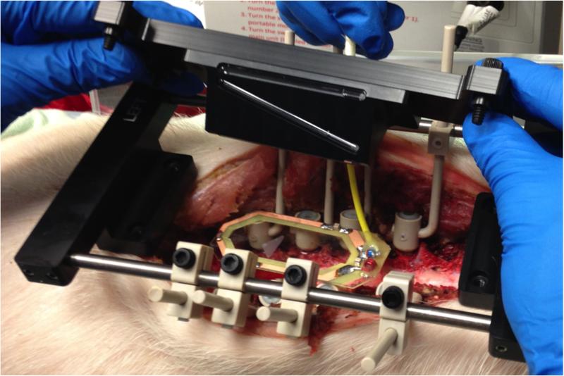
In the first pig, the MRI coil, and imaging fiducials were positioned within the surgical site and an MRI of the lumbar spinal cord was acquired (Figure 3). Next, MRI dicom images were transferred to COMPASS targeting software. Then, stereotactic coordinates were generated for a target point within the ventral horn of the lumbar spinal cord. After MRI-guided targeting, the stereotactic frame was placed onto the stabilization platform and a single tungsten microwire electrode (203 μm diameter), with a perfluoroalkoxy insulation coating removed to expose the tungsten tip approximately 50 μm (A-M Systems, Carlsborg, WA), was advanced into the spinal cord until frame system positioning matched the software-generated coordinates.
Figure 3.
System setup in pig lumbar spine. The stabilization platform, imaging coil, and fiducial system are mounted to the lumbar spine.
Once the intraspinal electrode was delivered, a reference electrode was inserted into the paraspinal musculature and both electrodes were connected to a wirelessly controlled, custom-built neurostimulation system (Mayo Investigational Neuromodulation Control System – MINCS).1,13 Biphasic, charge-balanced stimulation was delivered to the intraspinal electrode (50 Hz, 250 μs pulse width, 100 μA, 2 s duration). This stimulation was applied multiple times to ensure stimulation-evoked responses were repeatable. Hind limb muscle activity was captured via intramuscular electromyographic (EMG) needles placed within the biceps femoris. Once positioned, the needles were connected to wireless sensors that transmitted signals to windows-based software (Trigno Wireless EMG, Delsys Inc., Natick, MA) and offline analysis was performed using custom-written MATLAB code (The Mathworks, Natick, MA).
Following euthanasia (sodium pentobarbital 100 mg/kg, I.V.), a computed tomography (CT) scan was performed to examine electrode placement. The MRI used to guide electrode delivery was fused with the post-implantation CT to confirm electrode delivery into the targeted ventral horn region. Image fusion was performed manually using anatomical landmarks within both CT and MR images (VINCI, Max Planck Institute, Cologne, Germany).
2.4.4. Frame system adaptability to other spinal instrumentation: Intraspinal stimulation using a microelectrode array
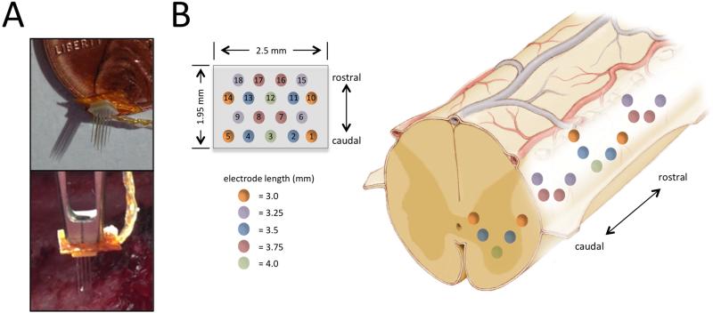
Using the same surgical approach as described above, without MRI-guidance, we tested the capability of the delivery system to implant an 18-microelectrode array (Floating Microelectrode Array, Microprobes for Life Sciences, Gaithersburg, MD) into the lumbar spinal cord in the second pig. The microelectrode array was mounted to the electrode guide cannula (Figure 4A) via cyanoacrylate adhesive and lead wires were connected to MINCS for wireless control of ISMS. The array was designed with varying electrode lengths (3.0 mm, 3.25 mm, 3.5 mm, 3.75 mm, and 4.0 mm), a mediolateral width of 1.95 mm and a rostrocaudal length of 2.5 mm, to allow examination of hind limb responses to stimulation at varied dorsoventral, mediolateral, and rostrocaudal locations (Figure 4B).
Figure 4.
System setup for delivery of 18-microelectrode array into spinal cord. (A) The microelectrode array was attached to the guide cannula for delivery into the spinal cord. (B) Microelectrode array dimensions and electrode configuration (Left) and approximate implantation of the microelectrode array within the lumbar spinal cord enlargement are shown (Right).
The frame and microarray assembly were mounted over the lumbar spinal cord enlargement and the array was positioned over the right dorsolateral surface of the spinal cord. Incremental advancement of the array into the right lumbar spinal hemicord was achieved via manipulation of the digital microdrive and guide cannula assembly. Stimulation was independently delivered to contacts 2 through 18 of the array while contact 1 remained the reference. Stimulation frequency (50 Hz), pulse width (200 μs), and duration (3 s) were held constant while stimulation amplitude was adjusted (from 30 to 90 μA) to identify stimulus intensities required to evoke muscle activity. Finally, the electrode configuration that was observed to be most sensitive (i.e., evoked strongest EMG signal at the lowest stimulus intensity) was chosen and stimulation intensity was increased in 10 μA increments from 10 to 50 μA.
Hind limb muscle activity was captured via intramuscular EMG needles placed within the biceps femoris, hamstrings, gluteus medius, and rectus femoris. EMG needles were connected to wireless EMG sensors that transmitted signals to windows-based software (Trigno Wireless EMG, Delsys Inc., Natick, MA). Finally, data were post-processed, filtered, and root mean square (RMS) signal envelopes were generated using MATLAB (The Mathworks, Natick, MA).
3. Results
3.1. System accuracy validation: phantom testing
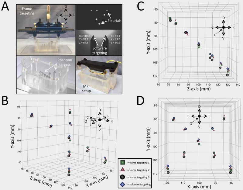
The experimental setup using nine phantom targets allowed comparison of actual frame coordinates to target software coordinates (Figure 5A). Three independent frame users generated coordinates for each target location and for visualization purposes; these coordinates were plotted in three orientations against software-generated coordinates (Figure 5B-D). RMS error between actual frame coordinates and target software coordinates for all coordinates generated was 1.23 mm for the first user, 0.86 mm for the second user, and 1.17 mm for the third.
Figure 5.
Accuracy testing in phantom. (A) Experimental setup for frame and software coordinates using an imaging phantom containing nine target points. (B-D) Frame coordinates generated by user one (green squares), two (red triangles), and three (black circles), are plotted against software-generated coordinates (blue diamonds) in multiple orientations for visualization purposes along the mediolateral (x), dorsoventral (y), and rostrocaudal (z) axes.
Directional abbreviations: R: rostral, C: caudal, D: dorsal, V: ventral, L: lateral, O: origin.
3.2 System accuracy validation: In vivo testing
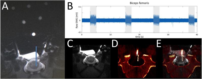
The 2-dimensional fast spin echo MRI scan provided a distinct definition of white and gray matter within the spinal cord, and allowed anatomical definition of ventral horn regions associated with motor function (Figure 6A). Electrode delivery to the target location resulted in electrode positioning capable of activating the biceps femoris muscle (Figure 6B). Fusion of the MRI and CT images in (Figure 6C-E) showed that frame positioning based on software-guidance resulted in an electrode position that matched the planned electrode location via software targeting.
Figure 6.
Accuracy testing in an anesthetized pig. (A) An implantation trajectory and final location were chosen (blue line) and stereotactic coordinates were generated using surgical navigation software based on fiducial orientation. (B) Biceps femoris activity was recorded via electromyography during stimulation (2 s stimulus duration, 50 Hz, 250 μs pulse width, 100 μA) at the target intraspinal location. (C) Pre-implantation MRI and (D) post-implantation CT images were fused (E) to confirm electrode delivery into target location.
3.3 ISMS-evoked responses via delivery of microelectrode array into lumbar spinal cord
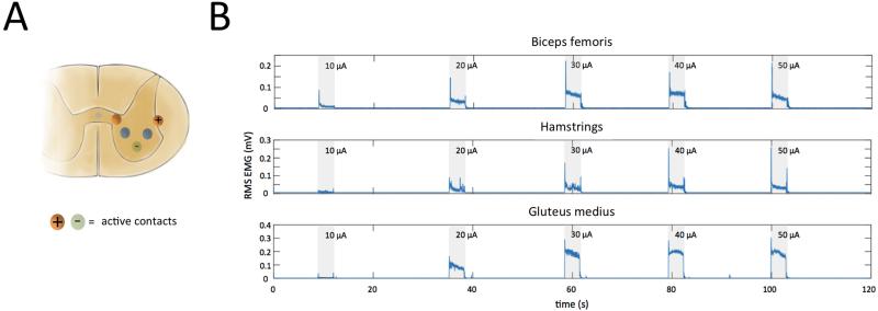
The stereotactic frame system successfully delivered the microelectrode array and maintained its position within the spinal cord for the duration of stimulation-evoked hind limb movements. Hind limb muscle activity was detected in the biceps femoris, hamstrings, rectus femoris, and gluteus medius muscles when spinal cord stimulation was applied through each contact of the microelectrode array, with the exception of contact 14 (Table 1). During stimulation with contact 14 an EMG equipment malfunction occurred, resulting in poor signal to noise ratio. Increasing stimulation amplitude from 10 to 50 μA (50 Hz, 200 μs, 3 s duration) in 10 μA increments, using active contact 1 and 3 (Figure 7A), produced a graded increase in muscle activity. Additionally, varying the stimulating contact resulted in activation of different muscles. However, varying the stimulation amplitude or the active contact did not increase muscle selectivity (Figure 7B, Table 1).
Table 1.
Muscle activity during minimum threshold stimulation.
| Active electrode |
Threshold stimulus (μA) |
Biceps femoris |
Hamstrings | Gluteus medius |
Rectus femoris |
|---|---|---|---|---|---|
| 1 | Reference electrode for all stimulus combinations | ||||
| 2 | 60 | ||||
| 3 | 10 | N | |||
| 4 | 30 | N | |||
| 5 | 60 | ||||
| 6 | 90 | N | N | ||
| 7 | 30 | ||||
| 8 | 30 | ||||
| 9 | 30 | ||||
| 10 | 60 | ||||
| 11 | 60 | ||||
| 12 | 30 | ||||
| 13 | 30 | ||||
| 14 | N/A | N | N | N | |
| 15 | 60 | ||||
| 16 | 90 | ||||
| 17 | 30 | ||||
| 18 | 60 | ||||
 = EMG detected
 = No EMG detected
 = Noise obscured EMG
Figure 7.
Muscle activity during intraspinal stimulation. (A) Stimulation (3 s stimulus duration, 50 Hz, 200 μs pulse width, 10 to 50 μA) was applied via microelectrode array contacts 1 (+) and 3 (−). (B) Intramuscular electromyography recordings from the biceps femoris, hamstrings, rectus femoris, and gluteus medius muscles evoked by stimulation (shaded regions) at increasing intensities ranging from 10 to 50 μA.
4. Discussion
While conventional FES techniques that rely on direct muscle or peripheral nerve stimulation have demonstrated the ability to restore muscle activity following paralysis, the limited number of degrees of freedom and rapid onset of muscle fatigue has limited clinical use of these techniques by SCI survivors.14 Intraspinal microstimulation is a form of FES with potential for clinical restoration of motor function after SCI. Stimulation via ISMS directly activates specific populations of motor neurons, potentially improving control of limb movement as well as reducing muscle fatigue. However, targeting specific motor neuron pools has proven difficult due to targeting errors and anatomical variability.15,16 Here, we describe a novel stereotactic system for overcoming the spatial inaccuracies associated with existing ISMS techniques which rely on anatomical landmarks of the dorsal spine and spinal cord for guiding electrode implantation. The MRI-guidance component of this system accounts for neuroanatomical differences by using subject-specific images to plan target locations and implantation trajectories.
Phantom testing revealed that the system presented provides a targeting accuracy of approximately 1 mm (0.86 to 1.23 mm), which may be sufficient for targeting substructures of the spinal cord such as the ventral horn. Unlike prior methods for ISMS electrode insertion that require 10 to 30 electrode insertions to identify optimal targets for evoking the desired motor responses,10,17,18 the system described herein will require fewer spinal cord penetrations to achieve a desired response. In turn, this results in reduced risk of tissue damage (i.e., hemorrhage, glial response, inflammation), and surgical time. Additionally, this system facilitates systematic mapping of populations of spinal motor neurons to evoke controlled, sustained, and reproducible limb movements.
Although the stereotactic system described will likely enhance ISMS techniques, we acknowledge the following limitations of the present system. The accuracy reported relies on a fixed target and it is important to recognize the spinal cord is a moving target in vivo due to its physiologic pulsations with the cardiorespiratory cycle. This can cause errors in MRI targeting due to motion artifacts. To this end, our MRI sequence was constructed to sync with the respiratory cycle, therefore minimizing respiratory motion artifact. Additionally, the pedicle screws and stabilization system used ensure that the frame moves in unison with the spine.
The delivery system described allows for accurate targeting within anatomical substructures of the spinal cord, but successful targeting of functional responses based on anatomical locations within the spinal cord remains to be seen. In order to successfully target stimulation-evoked functional responses, a high-resolution functional map of the spinal cord will be needed in order to deliver site-specific stimulation based on combined anatomical and functional maps. Preliminary functional maps have already been established in the rodent6, feline7,19, but none of these maps are capable of merging with a stereotactic coordinate system for utilization by an image-guided electrode delivery system.
Finally, while the MRI-guided system seeks to minimize the number of electrodes required for successful ISMS, implantation of rigid microwire electrodes inherently results in displacement of neural tissue and disruption of the blood brain barrier, thereby leading to inflammation and gliosis that can reduce stimulation efficacy. To this end, efforts should focus on developing novel electrode materials that 1) are biocompatible for chronic implantation, 2) minimize tissue disruption during insertion, and 3) are capable of stimulation at multiple sites along the electrode shaft.
5. Conclusion
Intraspinal delivery novel SCI therapeutics such as ISMS electrodes, enzymes to breakdown glial scar formation,20-23 biomaterials,24,25 regenerative cells,26,27 and growth factors,28-30 continue to emerge. These treatments require the discrete targeting of specific areas within the spinal cord. The stereotactic system described above was designed to accommodate delivery such therapies with a high degree of accuracy.
Here, we report the application of a novel MRI-guided stereotactic system for delivering ISMS following SCI. The accuracy of this system was tested both in a phantom and pig lumbar spine. Additionally, the system was tested for its ability to provide in vivo ISMS to evoke hind limb function. This system allows accurate delivery of intraspinal instrumentation within target neuron populations with a high degree of versatility, which can be easily adapted to accommodate emerging therapeutic applications.
Acknowledgement
The manuscript submitted does not contain information about medical device(s)/drug(s).
The Grainger Foundation and NIH NINDS (R21 NS087320) funds were received in support of this work.
Relevant financial activities outside the submitted work: grants.
References
- 1.Grahn PJ, Lee KH, Kasasbeh A, et al. Wireless control of intraspinal microstimulation in a rodent model of paralysis. Journal of Neurosurgery. 2014 Dec;:1–11. doi: 10.3171/2014.10.JNS132370. doi:10.3171/2014.10.JNS132370. [DOI] [PMC free article] [PubMed] [Google Scholar]
- 2.Hachmann JT, Jeong JH, Grahn PJ, et al. Kincaid AE, editor. Large Animal Model for Development of Functional Restoration Paradigms Using Epidural and Intraspinal Stimulation. PLoS ONE. 2013;8(12):e81443. doi: 10.1371/journal.pone.0081443. doi:10.1371/journal.pone.0081443.g002. [DOI] [PMC free article] [PubMed] [Google Scholar]
- 3.Pikov V, Bullara L, McCreery DB. Intraspinal stimulation for bladder voiding in cats before and after chronic spinal cord injury. J Neural Eng. 2007;4(4):356–368. doi: 10.1088/1741-2560/4/4/002. doi:10.1088/1741-2560/4/4/002. [DOI] [PMC free article] [PubMed] [Google Scholar]
- 4.Bamford JA, Mushahwar VK. Progress in Brain Research. Vol. 194. Progress in Brain Research; Elsevier: 2011. Intraspinal microstimulation for the recovery of function following spinal cord injury; pp. 227–239. doi:10.1016/B978-0-444-53815-4.00004-2. [DOI] [PMC free article] [PubMed] [Google Scholar]
- 5.Jonas B, Zimmermann AJ. Closed-loop control of spinal cord stimulation to restore hand function after paralysis. Front Neurosci. 2014;8 doi: 10.3389/fnins.2014.00087. doi:10.3389/fnins.2014.00087. [DOI] [PMC free article] [PubMed] [Google Scholar]
- 6.Sunshine MD, Cho FS, Lockwood DR, Fechko AS, Kasten MR, Moritz CT. Cervical intraspinal microstimulation evokes robust forelimb movements before and after injury. J Neural Eng. 2013;10(3):036001. doi: 10.1088/1741-2560/10/3/036001. doi:10.1088/1741-2560/10/3/036001. [DOI] [PMC free article] [PubMed] [Google Scholar]
- 7.Mushahwar VK, Horch KW. Selective activation of muscle groups in the feline hindlimb through electrical microstimulation of the ventral lumbo-sacral spinal cord. IEEE Trans Rehabil Eng. 2000;8(1):11–21. doi: 10.1109/86.830944. [DOI] [PubMed] [Google Scholar]
- 8.Zimmermann JB, Seki K, Jackson A. Reanimating the arm and hand with intraspinal microstimulation. J Neural Eng. 2011;8(5):054001. doi: 10.1088/1741-2560/8/5/054001. doi:10.1088/1741-2560/8/5/054001. [DOI] [PMC free article] [PubMed] [Google Scholar]
- 9.Bamford JA, Putnam CT, Mushahwar VK. Intraspinal microstimulation preferentially recruits fatigue-resistant muscle fibres and generates gradual force in rat. The Journal of Physiology. 2005;569(3):873–884. doi: 10.1113/jphysiol.2005.094516. doi:10.1113/jphysiol.2005.094516. [DOI] [PMC free article] [PubMed] [Google Scholar]
- 10.Saigal R, Renzi C, Mushahwar VK. Intraspinal Microstimulation Generates Functional Movements After Spinal-Cord Injury. IEEE Transactions on neural systems and Rehabilitation Engineering. 2004;12(4):430–440. doi: 10.1109/TNSRE.2004.837754. doi:10.1109/TNSRE.2004.837754. [DOI] [PubMed] [Google Scholar]
- 11.Mushahwar VK, Collins DF, Prochazka A. Spinal Cord Microstimulation Generates Functional Limb Movements in Chronically Implanted Cats. Experimental Neurology. 2000;163(2):422–429. doi: 10.1006/exnr.2000.7381. doi:10.1006/exnr.2000.7381. [DOI] [PubMed] [Google Scholar]
- 12.Goerss S, Kelly PJ, Kall B, Alker GJ. A computed tomographic stereotactic adaptation system. Neurosurgery. 1982;10(3):375–379. doi: 10.1227/00006123-198203000-00014. [DOI] [PubMed] [Google Scholar]
- 13.Chang S-Y, Kimble CJ, Kim I, et al. Development of the Mayo Investigational Neuromodulation Control System: toward a closed-loop electrochemical feedback system for deep brain stimulation. Journal of Neurosurgery. 2013;119(6):1556–1565. doi: 10.3171/2013.8.JNS122142. doi:10.3171/2013.8.JNS122142. [DOI] [PMC free article] [PubMed] [Google Scholar]
- 14.Grahn PJ, Mallory GW, Berry BM, Hachmann JT, Lobel DA, Lujan JL. Restoration of motor function following spinal cord injury via optimal control of intraspinal microstimulation: toward a next generation closed-loop neural prosthesis. Front Neurosci. 2014;8 doi: 10.3389/fnins.2014.00296. doi:10.3389/fnins.2014.00296. [DOI] [PMC free article] [PubMed] [Google Scholar]
- 15.Nashold BS, Friedman H, Grimes J. Electrical stimulation of the conus medullaris to control the bladder in the paraplegic patient. A 10-year review. Appl Neurophysiol. 1981;44(4):225–232. doi: 10.1159/000102205. [DOI] [PubMed] [Google Scholar]
- 16.Tai C, Booth AM, de Groat WC, Roppolo JR. Bladder and urethral sphincter responses evoked by microstimulation of S2 sacral spinal cord in spinal cord intact and chronic spinal cord injured cats. Experimental Neurology. 2004;190(1):171–183. doi: 10.1016/j.expneurol.2004.07.001. doi:10.1016/j.expneurol.2004.07.001. [DOI] [PubMed] [Google Scholar]
- 17.Mushahwar VK, Horch KW. Muscle recruitment through electrical stimulation of the lumbo-sacral spinal cord. IEEE Trans Rehabil Eng. 2000;8(1):22–29. doi: 10.1109/86.830945. [DOI] [PubMed] [Google Scholar]
- 18.Mushahwar VK, Stein RB, Prochazka A. Movement synergies elicited by intraspinal microstimulation compared to stimulation of muscles, nerves and roots in the cat. Proc Int Functional Electrical Stimulation Society. 2001 [Google Scholar]
- 19.Yakovenko S, Mushahwar V, VanderHorst V, Holstege G, Prochazka A. Spatiotemporal activation of lumbosacral motoneurons in the locomotor step cycle. Journal of Neurophysiology. 2002;87(3):1542–1553. doi: 10.1152/jn.00479.2001. [DOI] [PubMed] [Google Scholar]
- 20.Chau CH, Shum DKY, Li H, et al. Chondroitinase ABC enhances axonal regrowth through Schwann cell-seeded guidance channels after spinal cord injury. FASEB J. 2004;18(1):194–196. doi: 10.1096/fj.03-0196fje. doi:10.1096/fj.03-0196fje. [DOI] [PubMed] [Google Scholar]
- 21.Starkey ML, Bartus K, Barritt AW, Bradbury EJ. Chondroitinase ABC promotes compensatory sprouting of the intact corticospinal tract and recovery of forelimb function following unilateral pyramidotomy in adult mice. Eur J Neurosci. 2012;36(12):3665–3678. doi: 10.1111/ejn.12017. doi:10.1111/ejn.12017. [DOI] [PMC free article] [PubMed] [Google Scholar]
- 22.Bosch KD, Bradbury EJ, Verhaagen J, Fawcett JW, McMahon SB. Chondroitinase ABC promotes plasticity of spinal reflexes following peripheral nerve injury. Experimental Neurology. 2012;238(1):64–78. doi: 10.1016/j.expneurol.2012.08.003. doi:10.1016/j.expneurol.2012.08.003. [DOI] [PubMed] [Google Scholar]
- 23.Alilain WJ, Horn KP, Hu H, Dick TE, Silver J. Functional regeneration of respiratory pathways after spinal cord injury. Nature. 2011;475(7355):196–200. doi: 10.1038/nature10199. doi:10.1038/nature10199. [DOI] [PMC free article] [PubMed] [Google Scholar]
- 24.Hakim JS, Esmaeili Rad M, Grahn PJ, et al. Positively charged oligo[poly(ethylene glycol) fumarate] scaffold implantation results in a permissive lesion environment after spinal cord injury in rat. Tissue Eng Part A. 2015 Apr; doi: 10.1089/ten.tea.2015.0019. doi:10.1089/ten.TEA.2015.0019. [DOI] [PMC free article] [PubMed] [Google Scholar]
- 25.Grahn PJ, Vaishya S, Knight A, et al. Implantation of cauda equina nerve roots through a biodegradable scaffold at the conus medullaris in rat. Spine J. 2014 Feb; doi: 10.1016/j.spinee.2014.01.059. doi:10.1016/j.spinee.2014.01.059. [DOI] [PMC free article] [PubMed] [Google Scholar]
- 26.Chen BK, Knight AM, Madigan NN, et al. Comparison of polymer scaffolds in rat spinal cord: A step toward quantitative assessment of combinatorial approaches to spinal cord repair. Biomaterials. 2011;32(32):8077–8086. doi: 10.1016/j.biomaterials.2011.07.029. doi:10.1016/j.biomaterials.2011.07.029. [DOI] [PMC free article] [PubMed] [Google Scholar]
- 27.Olson HE, Rooney GE, Gross L, et al. Neural stem cell- and Schwann cell-loaded biodegradable polymer scaffolds support axonal regeneration in the transected spinal cord. Tissue Eng Part A. 2009;15(7):1797–1805. doi: 10.1089/ten.tea.2008.0364. doi:10.1089/ten.tea.2008.0364. [DOI] [PMC free article] [PubMed] [Google Scholar]
- 28.Deng L-X, Hu J, Liu N, et al. GDNF modifies reactive astrogliosis allowing robust axonal regeneration through Schwann cell-seeded guidance channels after spinal cord injury. Experimental Neurology. 2011;229(2):238–250. doi: 10.1016/j.expneurol.2011.02.001. doi:10.1016/j.expneurol.2011.02.001. [DOI] [PMC free article] [PubMed] [Google Scholar]
- 29.Lee YS, Lin CY, Jiang HH, DePaul M, Lin VW, Silver J. Nerve Regeneration Restores Supraspinal Control of Bladder Function after Complete Spinal Cord Injury. J Neurosci. 2013;33(26):10591–10606. doi: 10.1523/JNEUROSCI.1116-12.2013. doi:10.1523/JNEUROSCI.1116-12.2013. [DOI] [PMC free article] [PubMed] [Google Scholar]
- 30.Ren H, Han M, Zhou J, et al. Repair of spinal cord injury by inhibition of astrocyte growth and inflammatory factor synthesis through local delivery of flavopiridol in PLGA nanoparticles. Biomaterials. 2014;35(24):6585–6594. doi: 10.1016/j.biomaterials.2014.04.042. doi:10.1016/j.biomaterials.2014.04.042. [DOI] [PubMed] [Google Scholar]


