Abstract
Objective
This paper presents the three dimensional kinematic modeling of a novel steerable robotic ablation catheter system. The catheter, embedded with a set of current-carrying micro-coils, is actuated by the magnetic forces generated by the magnetic field of the magnetic resonance imaging (MRI) scanner.
Methods
This paper develops a 3D model of the MRI actuated steerable catheter system by using finite differences approach. For each finite segment, a quasi-static torque-deflection equilibrium equation is calculated using beam theory. By using the deflection displacements and torsion angles, the kinematic model of the catheter system is derived.
Results
The proposed models are validated by comparing the simulation results of the proposed model with the experimental results of a hardware prototype of the catheter design. The maximum tip deflection error is 4.70 mm and the maximum root-mean-square (RMS) error of the shape estimation is 3.48 mm.
Conclusion
The results demonstrate that the proposed model can successfully estimate the deflection motion of the catheter.
Significance
The presented three dimensional deflection model of the magnetically controlled catheter design paves the way to efficient control of the robotic catheter for treatment of atrial fibrillation.
Keywords: Steerable Catheter, Robotic Catheter, Magnetically Actuated Catheter, Catheter Deflection Model
I. Introduction
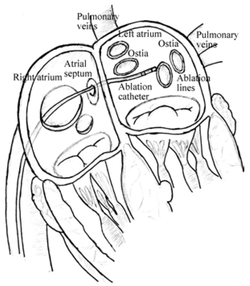
Catheter ablation is a widely performed interventional procedure for treatment of cardiac arrhythmia [1, 2]. During the procedure, the physician typically inserts a catheter into the femoral vein, and guides it into the right atrium, then penetrates it through the atrial septum into the left atrium, as shown in Fig. 1. The catheter tip reaches the desired area required by operator, such as, the ostia of the pulmonary veins (Fig. 1), and applies radiofrequency energy to build ablation barriers to prevent the spread of the irregular electrical signals. During the past decade, robotic-assisted catheter ablation has increasingly gained many researchers’ interest, due to its premise of stable manipulation of the catheter, precise navigation and dexterous control of the catheter tip, potentially leading to shorter procedure times and improved efficacy [3].
Fig. 1.
Illustration of catheter ablation procedure. [4]
This paper presents the three dimensional kinematic modeling of a steerable robotic ablation catheter system actuated by a novel actuation method which uses the magnetic field of a magnetic resonance imaging (MRI) scanner. In this actuation method, which was originally proposed by Roberts et al. [5] and also investigated by Gudino et al. [6], the catheter is embedded with a set of current-carrying micro-coils. The catheter is actuated by the magnetic forces generated by the magnetic field of the MRI scanner on these coils, by controlling the amount of current going through the coils. The kinematic configuration of the catheter and the deflection under force and torque loads are modeled using a finite differences approach. The deformation of each segment in the finite differences model is computed using beam theory under mechanical equilibrium conditions. The direct kinematic model is built by using these models.
During catheter ablation procedures [2], the catheter needs to access arbitrary locations on the inner surface of the heart chamber from a single entry point on the atrial septum, requiring large deflections. Additionally, the catheter needs to perform complex motions for electrophysiological mapping and ablation, such as for creating continuous scar tissue barriers around the ostia of the pulmonary veins (Fig. 1). In order to have the necessary workspace to perform these motions and to avoid motion singularities, the catheter needs to be actuated with multiple triaxial coil sets located at multiple places along its shaft [7]. Loading from different combinations of magnetic torques on these coil sets would lead to complex deflections with non-uniform curvature.
Our preliminary validation of the catheter’s deflection motion model was presented in our conference paper [4]. This conference paper [4] introduced the analytical model, but relied on a limited set of experimental data from an earlier study by Gudino et al. [6], which employed a preliminary proof-of-concept catheter prototype, for validation. The present paper has been substantially extended [4], with an improved catheter prototype, a new and more comprehensive set of experiments and a more detailed analysis. Specifically, in the present paper, a more sophisticated and realistic catheter prototype, which has two embedded triaxial coil sets, was used for the validation experiments. Additionally, all combined deflection motions generated by different combinations of magnetic torques were comprehensively validated.
The rest of the paper is organized as follows. Related studies in the literature regarding magnetically steerable catheter systems and catheter modeling are discussed in Section II. The modeling of the active catheter is presented in Section III. The experimental methods are described in Section IV. The validation of the proposed model is presented in Section V. The discussion and conclusions are presented in Sections VI and VII.
II. Related Studies
There are several types of active catheters proposed in the literature employing different actuation methods [3], including pull-wire actuated catheters [8-12], shape memory alloy (SMA) actuated catheters [13, 14], and magnetically actuated catheters [5, 6, 15-17].
Magnetic actuation is one of the active and growing actuation methods employed. A review of different remote control catheter navigation approaches under MRI is presented in [18]. The magnetic implants (permanent magnets, electromagnetic coils or ferromagnetic beads) on the catheter tip directly drive the catheter to deflect, without the mechanical transmission problems that exist in other actuation methods which place the actuators outside patient body. The magnetic actuation increases the bandwidth of the system by reducing backlash and friction.
In general, there are three ways of using magnetic actuation for catheter’s navigation. The first method is to place a permanent magnet on the catheter tip and stay in an external magnetic field. The Niobe® ES magnetic navigation system (Stereotaxis, St. Louis, MO) utilizes two permanent magnets mounted on two pivoting arms located on either side of surgical bed to navigate the catheter [15]. The catheter, which has a permanent magnet mounted on its distal tip, is placed in the external magnetic field created by the two external permanent magnets which can selectively change directions and magnitudes. The attraction and repulsion of the magnetic forces are then used to deflect the catheter as desired. The second method replaces the permanent magnets with ferromagnetic materials. Gosselin et al. [16] showed that a catheter with ferromagnetic beads attached on its tip can be bent and steered inside an MRI system by using magnetic gradients. The third approach is to utilize the physical phenomenon that a current-carrying electromagnetic coil in an external magnetic field is able to produce a magnetic torque. Roberts et al. [5], Settecase et al. [17], and Gudino et al. [6], separately demonstrated that a catheter with an array of current-carrying coils mounted on its distal tip can perform an arbitrary 3-dimensional deflection inside a clinical MRI scanner.
There are a number of earlier studies on modeling of a catheter under a combined loading. Generally, there are two methods studied in the literature. The first method is to treat the deflected catheter as a cantilever beam under a combined load. Large deflection models of cantilever beams in a 2-dimensional plane are proposed in the field of mechanics of material [19-21]. One end of the cantilever beam is fixed and the other end is free. Both Settecase et al. [17] and Lillaney et al. [22] modeled the catheter with one axial coil on its tip as a cantilever beam by equaling a torque induced by the magnetic moment of the current-carrying coil interacting with the magnetic field of the MRI scanner to the mechanical restoring torque of the catheter. Gosselin et al. [16] modeled a catheter with several ferromagnetic beads attached on its tip in a clinical MRI scanner as a Euler-Bernoulli Beam of uniform flexural rigidity. Khoshnam et al. [11] modeled the distal section of a catheter by using beam theory. However, these traditional beam theories are not directly extendable to the 3-dimensional catheter deflections as well as torsions. The beam theory can not solve the problem with large deflection angles. Additionally, Cotin et al. [23] assumed the catheter is composed of wire-like segments and developed an incremental finite element model based on beam theory.
The second method is to model a catheter in a static equilibrium by locally minimizing its total potential energy. Lawton et al. [24] used rotation group and its algebra to derive the Euler differential equations that described the equilibrium configurations of catheters through potential energy relations. Furthermore, Tunay [25] developed a simpler quasi-3D Lawton’s model. An extended model including inflation, bending, twisting, extension, and shear deformation by locally minimizing the total potential energy of the catheter, was proposed by Tunay in [26]. Similarly, Rucker et al. [27] used the stored elastic energy in the backbone of an active cannula to model the combined motion of bending and torsion motions.
This paper proposes a new approach combining finite differences approach, beam theory and rotation groups to analyze the catheter’s 3D deflection motion. The model incorporates the bending and torsion motions. First, the catheter is approximated to be composed of a set of finite segments. The deflection problem of each small segment is assumed to have small deflection angles and solved by the beam theory and the Bernoulli-Euler law. Once each segment’s deflection angles and torsion angle are known, the positions of all points on this segment can be found. Considering each segment as a continuum robotic link bending with constant curvature, the homogeneous transformation relationship between the two ends of the segment is calculated. The mechanical equilibrium equations of each segment are then set up to relate the deflection angles of each segment to the link force and torques.
In addition to the tip position, proper control of the catheter requires accurate estimation of the coil orientations, as the actuation torques depend on the orientation of the coils relative to the magnetic field direction (as given by (4) and (12) in Section III-B). However, in [11, 16, 17, 22], only deflection angles of the catheter tip were used to validate the models with the experimental data. In this study, both the estimated catheter tip positions and the estimated shapes of the catheter are compared with the experimental data for validating the proposed model.
The contribution of this paper is to provide a kinematic model of a magnetically-actuated catheter which is subjected to external torques and forces acting on multiple locations. The proposed model is extensively validated in hardware experiments using MR imaging, which demonstrated a good agreement between the model predictions and the measurements of the actual catheter deflection. An effective kinematic model paves the way to efficient control of the robotic catheter system. The proposed model can not only be applied to catheters, but also to the kinematic modeling of other continuum robots which have emerging medical applications.
III. Methodology
A. Active Catheter Description
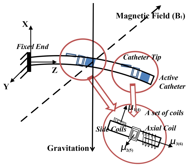
The catheter prototype with a fixed end at its base is placed in a uniform magnetic field (Fig. 2). The catheter prototype is constructed by embedding two sets of current-carrying coils to a microcatheter (a polymer tube). Each set of coils includes one (or more) axial coil, and two (or more) orthogonal side coils. The catheter is subjected to a combined loading from the weights of catheter and steering coils, and buoyancy from the fluid inside the left atrium. When the coils are excited, it will be additionally subjected to two sets of external magnetic torques from the coils.
Fig. 2.
Illustration of a catheter prototype in a magnetic field, including two sets of embedded current-carrying coils.
Several assumptions are used: 1) the catheter is made of a linear material, which is homogeneous and isotropic,1 2) the shear stresses are negligible,2 3) the catheter is non-extensible and the strains remain small, 4) the Bernoulli-Euler hypothesis is valid,3 and 5) the bending motion and torsion motion are linearly independent.
The focus of this paper is to model the deflection motions of the catheter inside the left atrium (Fig. 1). In the ablation procedure, the catheter accesses the left atrium by penetrating through the atrial septum from the right atrium. This penetration results in substantial friction at the entry location. Therefore, the catheter can be assumed to be fixed to the atrial septum.
B. Modeling of Catheter Deflection Mechanism in Free Space
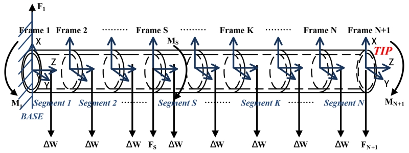
As classical beam theory can not solve large deflection problems, such as, of a long catheter, this paper employs a finite differences approach to analyze the deflections by dividing the catheter into N short segments (shown in Fig. 3). Each segment has two coordinate frames attached to its two ends. Observed from left to right, the frames are specified as frame 1, frame 2, ⋯, frame N, and frame N + 1. The coordinate frame 1 is catheter’s base frame. Here, the rotation matrix R and the rigid body homogeneous transformation g are used to represent the transformation relationship between any two frames.
Fig. 3.
Diagram of a catheter equipped with two sets of embedded current-carrying coils, which is divided into N finite segments.
In Fig. 2, the vector represents the magnetic field relative to the base frame, [Bx, By, Bz]T. , , and represent the magnetization vectors of coil 1, coil 2 and coil 3 relative to frame N + 1, as shown in Fig. 2. , , and can be expressed in coordinate frame N + 1 as , , and . Hence, the total magnetization vector relative to frame N + 1 is as follows:
| (1) |
where Nj represents the number of turns in the coil j, Aj is the area enclosed by each turn of the coil j, and ij is the current through the coil j. Similarly, , , and represent the magnetization vectors of coil 4, coil 5 and coil 6 relative to frame S. Therefore,
| (2) |
1) Equilibrium Configurations of the Individual Segments
As the catheter is only virtually divided into finite segments, each segment is still affected by the interactive forces and torques from its neighboring segments. Therefore, each segment’s equilibrium configuration is analyzed in an appropriate order. This paper starts from the Nth segment to the 1st segment.
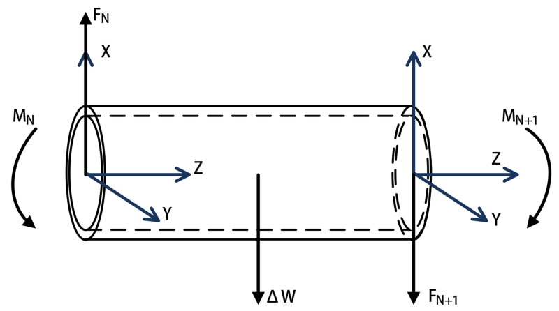
The Nth segment (shown in Fig. 3) is embedded with an array of active coils. The free-body diagram of the segment (shown in Fig. 4) shows that the forces and torques on the two ends of the segment realize an equilibrium configuration, individually. As it is shown in Fig. 4, frame N and frame N + 1 located at the proximal and distal ends of the segment, respectively. At the distal end, the force FN+1 and the torque MN+1 can be represented relative to the frame N + 1,
| (3) |
| (4) |
where is the total weight of the distal coil set 4, and RN+1,1 represents the rotation matrix between the frame N+1 and the frame 1. The cross product of the magnetization vector μN+1 and the magnetic field vector transformed from frame 1 to frame N + 1 computes the magnetic torques generated on the coils with respect to the frame N + 1.
Fig. 4.
Equilibrium configurations of the last segment.
According to the equilibrium conditions, the force FN and the torque MN on the left side are computed as
| (5) |
| (6) |
where ΔW, assumed as a lumped force, represents a combined force of the weight of the catheter segment and the buoyancy from the fluid, PN,N+1 represents the vector between the frame N and the frame N + 1, and QN,N+1 represents the vector between the frame N and the center of this segment.
The free-body diagrams of the (N − 1)th and Nth segments (shown in Fig. 5) show that the equilibrium conditions of the (N − 1)th segment are,
| (7) |
| (8) |
Fig. 5.
Equilibrium configurations of two neighbor segments.
Similarly, for the rest of the segments except the Sth segment, the force and torque equilibrium equations can be written for the Kth segment, K ∈ {N − 2, ⋯, S + 1, S − 1, ⋯, 1}, as
| (9) |
| (10) |
The equilibrium conditions of the Sth segment due to the magnetic torques from the proximal coil set are
| (11) |
| (12) |
where is the total weight of the proximal coil set relative to the base frame 1.
2) Deflection Modeling of the Individual Segments
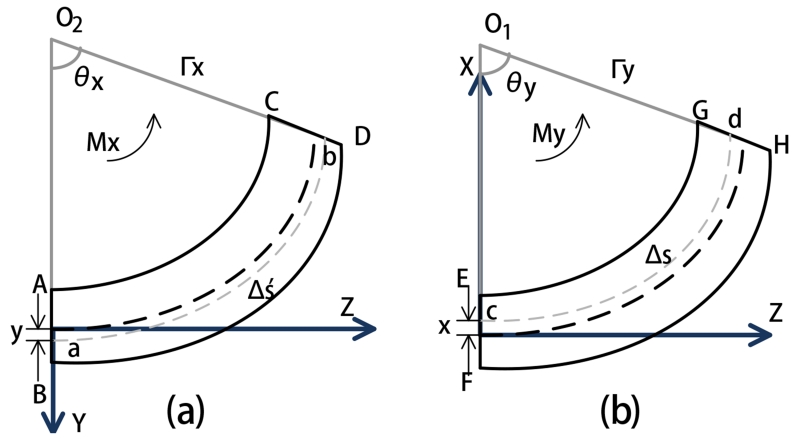
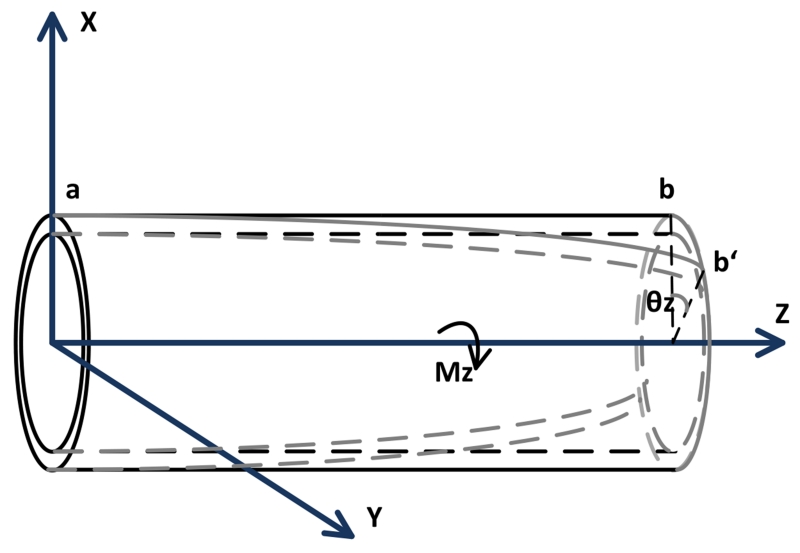
The deflection of each segment is subject to two bending motions in its X and Y axes (shown in Fig. 6), and the torsion motion around its Z axis shown in Fig. 7)5.
Fig. 6.
Diagrams of the deformations of one segment by bending in YZ and XZ planes. (a) Bending in YZ plane. (b) Bending in XZ plane.
Fig. 7.
Diagram of the deformation of one segment by a torsion.
Fig. 6(a) shows that a segment subjected to bending by the torque Mx around the positive X axis. The deflected segment in YZ plane is assumed to be a uniform circular curve. The two line segments AB and CD represent the intersection of the YZ plane with the two planes perpendicular to the neutral axis of the segment. The extensions of AB and CD intersect at point O2, the center of the circularly deformed segment covering an arc of θx radians. The radius from the center O2 to the neutral axis is represented by Γx. The curve ‘ab’ is at a distance y from the neutral axis on the positive Y axis. Δs′ represents the arc length of the neutral axis.
As the segment has a small deflection, we can approximate
| (13) |
where Δz is the length of each segment. So the geometry of the sector is
| (14) |
The relation of the arc length of ab and the strain of this segment, and the stress-strain relation from Hooke’s law, can extend (14) to yield
| (15) |
Similarly, the deflection in the XZ plane (shown in Fig. 6 (b)), can be calculated as
| (16) |
Therefore, the normal stress can be calculated as
| (17) |
following an analysis similar to [28], where Ix and Iy are the area moments of inertia of the segment cross section with respect to the X and Y axes, respectively, and Ixy is the area product of inertia of the segment cross section.
The bending angles θx and θy can be respectively represented as a function of torques applied Mx and My using (15), (16), and (17) with x = 0 and y = 0,
| (18) |
Fig. 7 shows the torsion motion of the catheter subjected by the torque vector Mz along the Z axis. The torsion equation is
| (19) |
where θz is the torsion angle, G is the shear modulus and J is the polar moment of inertia [28].
Algebraically, (18) and (19) can be arranged into a matrix form as
| (20) |
where
and
Given the coil currents ij (j = 1, ⋯, 6), the simultaneous numerical solution of deflection model equations (20) for all of the segments together with the mechanical equilibrium equations (3-12) would yield the deflection and torsion angles for all segments.
Given the deflection angles, the kinematics of each segment can be treated as a 3 DoF continuum robotic link defined by the differential equation [27, 29],
| (21) |
where the deformed shape of the segment is described by a coordinate frame g(s) ∈ SE(3) parameterized with the arc length s along the centerline of the catheter. Here, the twist
where the unit vector of the rotation, ω, and the unit vector of the translation along the centerline of the catheter, ν, are defined as
and
where and s0 is the total length of the segment along the centerline. The resulting position and orientation of the end point of the segment is given by [30]
| (22) |
where Rodrigues’ formula [30] gives
| (23) |
IV. Experiment Descriptions
A. Description of Catheter Prototype
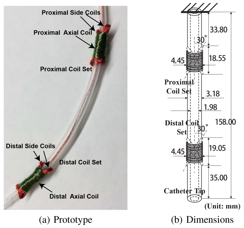
The catheter prototype used in the experimental validation is embedded with two current-carrying coil sets, namely, a proximal coil set and a distal coil set, as shown in Fig. 8(a). Each coil set includes one 130-turn axial coil and two 30-turn side coils. The two side coils are bound as an X-shaped cross and secured tightly by the axial coil, such that the net magnetization vectors of the X-shaped configurations are along the desired orthogonal directions.
Fig. 8.
A proof-of-concept catheter prototype used in the experiment and its dimensions.
The coils are made of heavy insulated 38-gauge electromagnetic wires with enameled copper (Adapt Industries, LLC, Salisbury, MD). They are built over a silicone tubing (Part number: T2011, QOSINA, Edgewood, NY). The outer diameter of the tubing is about 3.18 mm and the inner diameter is about 1.98 mm, as shown in Fig. 8(b). The resulting length of the catheter is 158.00 mm long. The diameter of the axial coil is around 4.45 mm. The lengths of the proximal coil set and distal coil set are around 18.55 mm and 19.05 mm, respectively. The angle between the tilted side coil and the vertical axis is around 30°.
B. Experiment Setup
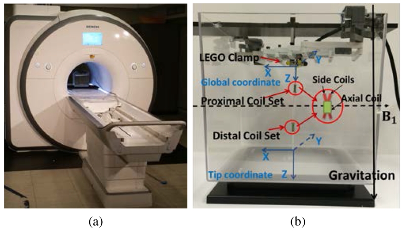
The experiments are conducted inside a 3T clinical scanner (Skyra, Siemens Medical Solutions, Erlangen, Germany), as shown in Fig. 9(a). The catheter prototype is immersed in a phantom filled with water which is placed at the isocenter of the MRI scanner.
Fig. 9.
(a) Experiment setup inside a clinical MRI scanner. (b) Sideview of the experiment setup. The prototype carrying two coil sets (proximal coil set and distal coil set) is clamped vertically by a mechanism made from plastic parts. The dashed line represents the direction of the magnetic field and the solid line represents the direction of gravity.
Fig. 9(b) shows the sideview of the experiment setup. The prototype is mounted vertically to an aquarium tank. The clamp for fixing one end of the catheter is made from plastic parts. The global coordinate frame and the tip coordinate frame are attached to the catheter’s base and tip. The Z axis of the global coordinate points along the direction of the catheter. The X axis points against the direction of the magnetic field. In the zero configuration of the catheter6, the axes of the global and tip coordinate frames are aligned. The direction of the magnetic field points horizontally from left to right. The direction of the gravitation points vertically down. Additionally, Fig. 9(b) shows the horizontal component of flux coming from the X-shaped side coil, which is parallel to the direction of the magnetic field.
The cables of the coils are connected to a current amplifier circuit box which stays outside the MRI room. The current for each coil is modulated independently by pulse width modulation (PWM). In this paper, the upper limit for the amplitude of the current for each of the coils is set to 200 mA.
C. MRI image acquisition process
MR images were acquired using a 3D FLASH sequence. Imaging parameters were adjusted for sufficient tip and shaft visualization to measure deflection: repetition time (TR) = 5.10 ms; echo time (TE) = 2.53 ms; flip angle = 5; in-plane resolution = 2.19 mm × 2.19 mm; matrix = 128 × 84 to 128 × 128; field-of-view = 280 mm × 183 mm to 280 mm × 280 mm; partition thickness = 5 mm; bandwidth = 795 Hz/pixel. A total of 32 partitions were collected per slab, although the catheter may have appeared in only a few. DICOM images7 were reconstructed at the scanner, and no further post-processing was performed on these images.
The catheter was detectable by signal voids, caused by local field distortion, surrounding the coils when the coils were driven with current. When the catheter was neutral (no current driven), the catheter was visible due to displacement of water by the catheter [31].
The MRI scanner scans the catheter after waiting for a set amount of time (a few seconds) from the application of the excitation currents. In this amount of time, the steady state of the catheter is reached when the vibrations of the catheter resulting from actuation die down. The duration of the vibrations is visually observed.
D. Actual deflection measurement
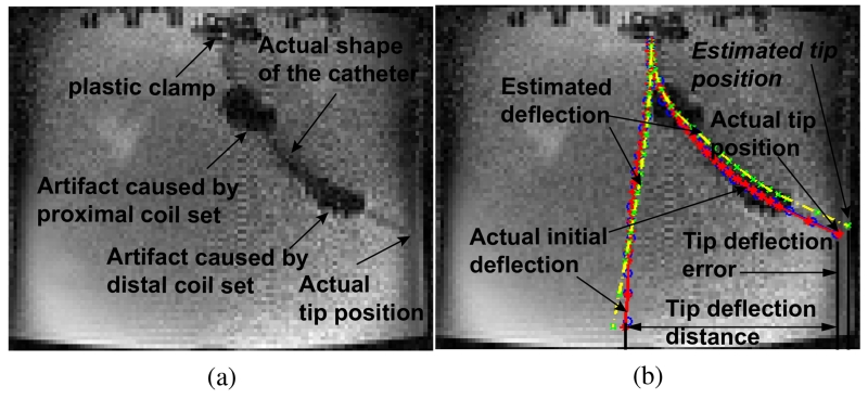
Fig. 10(a) shows an example of the catheter’s deflection in an MR image from a single cross-sectional image plane. The two large artifacts caused by the current-carrying coils enable the visualization of the approximate locations of the coils in the MR image. The shape of the deflected catheter is also detectable. The black line segment artifacts on the top of the Fig. 10 are the plastic clamps used to attach the catheter. The left and right edges of the image represent the front and back walls of the aquarium tank. The pixel size of the image is 2.19 mm × 2.19 mm.
Fig. 10.
(a) One example of an original MR image which captures the deflection of the catheter. (b) Illustration of the method of deflection measurement.
In order to visually compare the actual deflection of the catheter with the estimated deflection by the model, the MR image is loaded into Matlab®. The detected shaft of the catheter is approximately identified by manually selecting a series of markers from the centers of the visualized catheter shaft. For example in Fig. 10(b), the blue circles represent the shaft of the catheter in the MR image. Then these blue circles are then fitted to a smooth curve (shown as a red polynomial curve in Fig. 10(b)) by using polynomial curve fitting as a representation of the actual shape of the catheter. The red stars on the curve represent the end points of each segment on the catheter which are used in the model. The yellow dashed curve represents the estimated shape of the catheter from the model. The green cross markers represent the end points of each segment.
In Fig. 10(b), another red solid curve and yellow dashed curve corresponding to the initial shape of the catheter when no currents pass any coils are manually imposed for illustrating the deflection measurement method. Specifically, the lateral distance between two tip locations marked in a red star represents the actual deflection distance of the catheter. The lateral distance between the estimated tip location marked in a green cross and the actual tip location marked in a red star is the tip deflection error. The lateral distance between a pair of two corresponding segment points from the actual shape and the estimated shape gives the error in the catheter’s shape estimation for this point. A root-mean-square (RMS) error is calculated by using all these segment errors to evaluate the performance of the model. In this paper, the shape of the catheter is measured using a single (cross-sectional) image plane. Therefore, all lateral distances and the deflection errors are calculated in 2D.
V. Results
A. Experimental Results
The purpose of the hardware experiments is to validate the presented catheter deflection model by exciting the coils in a large range of current values so as to cover as much of the workspace as possible. However, it would not be practical for a physical experiment to perform an exhaustive search (i.e., exciting with every possible current combination). Therefore, a total of 6 different sets of experiments were performed for validation of the model. Each experimental excitation set corresponds to a different excitation pattern for the coils resulting in qualitatively different deflections of the catheter. These experiments can be categorized into two groups:
-
1)Exciting the proximal axial coil first and then the distal axial coil:
-
a)Case 1-a: positive currents for both axial coils,
-
b)Case 1-b: positive current for the distal axial coil and negative current for the proximal axial coil,
-
c)Case 1-c: negative current for the distal axial coil and positive current for the proximal axial coil,
-
d)Case 1-d: negative currents for both axial coils,
-
a)
-
2)Exciting the distal axial coil first and then the distal side coils:
-
a)Case 2-a: positive currents for both of the distal axial coil and the distal side coils,
-
b)Case 2-b: positive current for the distal axial coil and negative currents for the distal side coils.
-
a)
These experiments implemented all the excitation patterns of the coils for the catheter to perform planar motions.
In each experiment, two coils were excited sequentially by gradually increased currents. Table I lists the actual currents for each coil in each experiment. The current index represents every step in each experiment. The Index 0 represents the initial configuration of the catheter without any current passing through any coil. In some experiments, the currents were not increased up to the amplitude limit as the catheter tip would collide with the wall of the aquarium tank when the currents were too large.
TABLE I.
Currents for the coils in the experiments. The unit in the table is milliamps (mA).
| Currents Index | |||||||||||||
|---|---|---|---|---|---|---|---|---|---|---|---|---|---|
| 0 | 1 | 2 | 3 | 4 | 5 | 6 | 7 | 8 | 9 | 10 | 11 | ||
| 1-a | distal axial coil | 0 | 9 | 30 | 49 | 78 | 109 | 127 | 148 | 117 | 147 | ||
| proximal axial coil | 0 | 7 | 30 | 49 | 80 | 109 | 129 | 149 | 148 | 119 | |||
| 1-b | distal axial coil | 0 | 19 | 30 | 48 | 79 | 107 | 131 | 154 | 178 | 198 | 120 | 150 |
| proximal axial coil | 0 | −11 | −30 | −50 | −81 | −110 | −131 | −149 | −176 | −201 | −149 | −120 | |
| 1-c | distal axial coil | 0 | −10 | −31 | −52 | −81 | −109 | −130 | −151 | −174 | −200 | −121 | −151 |
| proximal axial coil | 0 | 10 | 30 | 51 | 81 | 109 | 130 | 151 | 176 | 201 | 151 | 119 | |
| 1-d | distal axial coil | 0 | −26 | −28 | −55 | −78 | −120 | −129 | −121 | −150 | |||
| proximal axial coil | 0 | −7 | −28 | −35 | −80 | −110 | −130 | −149 | −118 | ||||
| 2-a | distal axial coil | 0 | 200 | 200 | 200 | 200 | 200 | 200 | 200 | ||||
| distal side coil 1 | 0 | 10 | 30 | 50 | 78 | 110 | 129 | 0 | |||||
| distal side coil 2 | 0 | 11 | 32 | 50 | 79 | 110 | 131 | 0 | |||||
| 2-b | distal axial coil | 0 | 200 | 200 | 200 | 200 | 200 | 200 | 200 | ||||
| distal side coil 1 | 0 | −10 | −30 | −50 | −80 | −112 | −130 | 0 | |||||
| distal side coil 2 | 0 | −11 | −30 | −51 | −79 | −109 | −131 | 0 | |||||
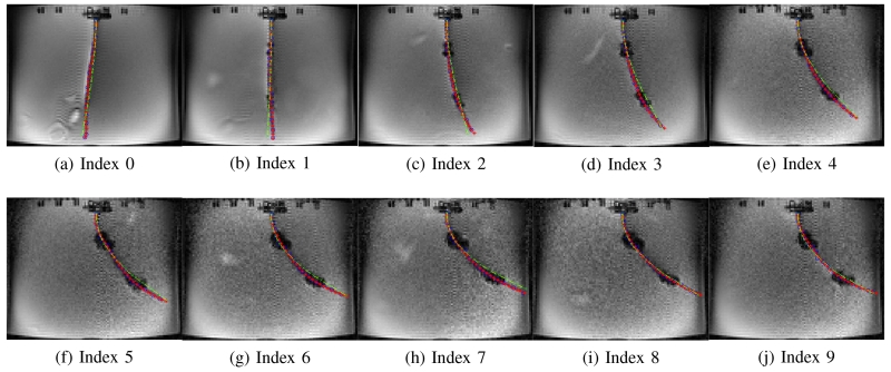
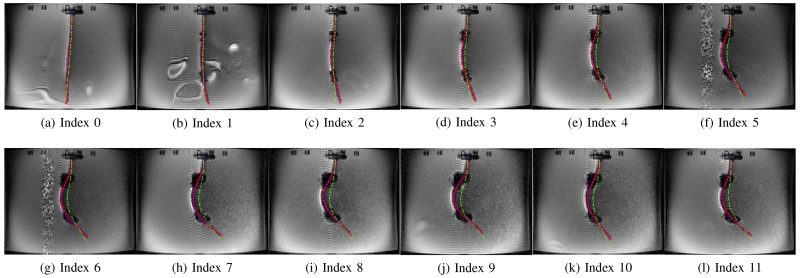
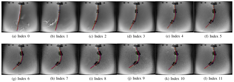
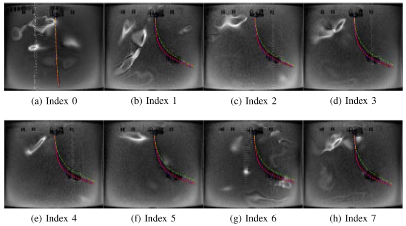
Figs. 11 - 16 show the actual deflected shapes of the catheter in the experiments listed in Table I. The red fitted curves represent the actual shapes of the catheter. For example, Fig. 11 shows a series of the sequential deflections of the catheter by exciting the proximal and distal axial coils with positive currents (refer to Case 1-a in Table I). With the increasing axial coil currents, the sizes of the two artifacts are becoming larger. As the positive currents for both axial coils produce counterclockwise torques, the catheter is deflected counterclockwise. Fig. 11(a) shows the initial configuration of the catheter when the Current Index is 0 in Table I. In Case 1-d, both currents are reversed, resulting in a clockwise deflection.
Fig. 11.
Validation of the catheter deflection in Case 1-a.
Fig. 16.
Validation of the catheter deflection in Case 2-b.
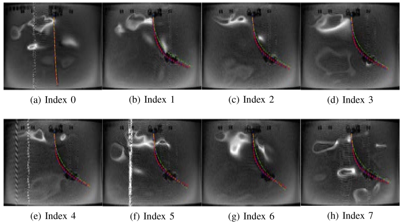
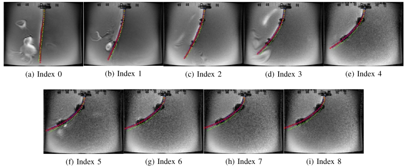
In Case 1-a and Case 1-d, the catheter is deflected to one direction as both axial coils produce the magnetic torques in the same direction. Therefore, in Figs. 11 and 14, the tip of the catheter almost collides the wall of the tank. In Cases 1-b and 1-c, the directions of the torques on the two axial coils are opposite; so, the proximal section of the catheter is deflected in the opposite direction of the distal section of the catheter as shown in Figs. 12 and 13. Specifically, in Case 1-b the proximal section deflects in clockwise direction and distal section in counterclockwise direction, and inversely in Case 1-c. In Case 2-a and 2-b, the side coils are excited to deflect the catheter further or less (respectively) from the deflection generated by the excitation of the distal axial coil with 200 mA.
Fig. 14.
Validation of the catheter deflection in Case 1-d.
Fig. 12.
Validation of the catheter deflection in Case 1-b.
Fig. 13.
Validation of the catheter deflection in Case 1-c.
Fig. 17(a) shows the deflection distances of the catheter with respect to its initial configuration, as determined by using the measurement approach introduced in Section IV-D. The black dashed lines represent the initial tip position of the catheter in each case.
Fig. 17.
(a) Tip deflection distances of the catheter. (b) Distance errors between the estimated tip location and actual tip location.
A video attached to this manuscript demonstrates the catheter motions inside the MRI scanner. The experimental setup in the video is slightly different from the setup shown in Fig. 9. A mirror is placed next to the aquarium tank for displaying the side motions of the catheter, as a camera can not capture the side motions of the catheter well from outside the MRI scanner bore.
B. Estimation of Material Parameters
Estimation of catheter deflection using the model presented in Section III requires the mechanical parameters of the catheter material. The material of the catheter tubing used for manufacturing the catheter prototype is silicone. However, the manufacturer only provided a relatively large range of the mechanical parameters, not their specific values. Therefore, the mechanical parameter values of the catheter material is estimated using a small subset of the experimental deflection data collected.
The mechanical properties of silicon-based polymer material are summarized in [32]. The ranges of Young’s modulus, density, and Poisson ratio are from 1 MPa to 50 MPa, from 1100 kg/m3 to 2300 kg/m3, and from 0.47 to 0.49, respectively. The density of the tubing material was measured to be approximately 1120 kg/m3, as it is made of a homogeneous material. Noting that the provided range of Poisson ratio is very tight, a value of 0.47 was used in the model. As the prototype carries six coils and the wires for these coils pass through the inner tunnel of the catheter to connect to the current source, all these factors will affect the ultimate flexural rigidity of the catheter together with the material of the tubing. The model approximates the catheter prototype to have a uniform flexural rigidity along the shaft. Given these observations, and the given large range of the Young’s modulus provided (covering a 50× range), it was necessary to experimentally estimate the Young’s modulus value.
As it can be seen in Figs. 11 - 16, the initial shape of the catheter in each case is not straight due to uncertain initial bending of the catheter. The initial deflections are not all the same in each case as the experiments were conducted in different days. In order to validate the model with the experiment results, this rest bending of the catheter is approximately modeled by an external force acting on the catheter tip, which also needs to be estimated.
Four experimental data points selected from each case together with the corresponding rest shapes of the catheter (corresponding to zero current value) were used for estimating the Young’s modulus and the virtual external forces.8 The estimation was performed by minimizing the errors between the actual deflection and the estimated deflection, including the tip deflection errors and the shape estimation errors, which are described in Section IV-D. The resulting estimate of the Young’s modulus is 10.15 MPa.
C. Validation Results
The validation results of the proposed model are presented in Figs. 11 - 18. The deflection of the catheter estimated by the model (a yellow dashed curve with green cross markers representing the end points of the segments) is superimposed on the MR images showing actual deflections of the catheter for each of the different experiment sets in Figs. 11 - 16. In this paper, the number of the segments on the catheter is 27.
Fig. 18.
(a) RMS errors of the shape estimation. (b) Maximum errors of the shape estimation.
Fig. 17(a) presents the actual tip deflection of the catheter for the different excitation cases. Fig. 17(b) represents the error between the estimated and actual tip deflections (the lateral distance from the actual tip position and the estimated tip position). The maximum errors for each case are 3.75 mm, 2.34 mm, 3.51 mm, 4.70 mm, 3.24 mm and 2.65 mm, respectively, which demonstrate that the model estimates the tip locations well.
Additionally, the error between the estimated and actual shape of the catheter is reported in Fig. 18. The shape error is calculated using the position errors between the locations of the segment end points on the estimated and actual shapes of the catheter. The RMS errors calculated from these difference errors are shown in Fig. 18(a). The maximum RMS errors in each case are 1.47 mm, 3.19 mm, 3.48 mm, 3.42 mm, 3.22 mm and 2.72 mm, respectively. The maximum difference error among the segment errors in each deflection is shown in Fig. 18(b). The maximum difference errors among all the difference errors of all the segments for each case are 8.21 mm, 11.24 mm, 12.49 mm, 10.28 mm, 9.35 mm and 7.78 mm, respectively.
VI. Discussion
The catheter’s deflections estimated by the proposed model match with the experimental results. The maximum tip deflection error is 4.70 mm. The estimated shapes of the catheter also match the actual shapes of the catheter in MR images. The maximum RMS error of the shape estimation is 3.48 mm and the maximum error is 12.49 mm.
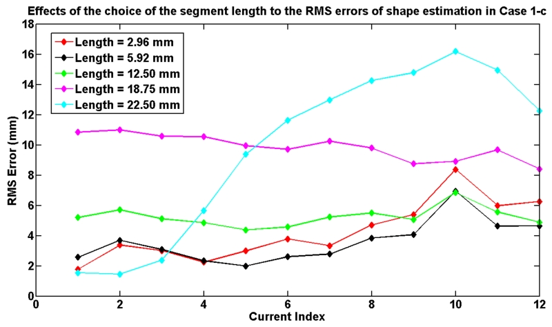
The number of segments, which determines the length of each of the segments used in the model, affects the computation speed of the model and the accuracy. To demonstrate these effects, the Case 1-c is used as an example to evaluate the effects of segment length. Fig. 19 shows the relationship between the RMS errors of shape estimation and the choice of the segment length used in the model. Table II shows the corresponding computation times9. The results show that the computation time increases with the number of segments. The results also show that the model error decreases as the segment length decreases up to a certain level at which point the unmodeled effects start to dominate.
Fig. 19.
The effects of the selection of segment length to the RMS error of the shape estimation in Case 1-c.
TABLE II.
Model computation times for different numbers of segments used in the model.
| Segment Length (mm) | 2.96 | 5.92 | 12.56 | 18.75 | 22.50 |
| Number of Segments | 53 | 27 | 13 | 9 | 7 |
| Computation Time (s) | 22.95 | 6.81 | 2.28 | 1.44 | 1.09 |
In order to evaluate the assumption of the approximation of the arc length in (13), two experimental cases (Current Index 8 in Case 1-a and Current Index 6 in Case 1-c) are arbitrarily selected. For the Current Index 8 in Case 1-a, the maximum difference between the arc length of a segment and its original length when the catheter is in its initial configuration is 0.23 mm. For the Current Index 6 in Case 1-c, the maximum difference between the arc length of a segment and its original length is 0.23 mm. This value, 0.23 mm, is computed by the curve length Δs′ subtracted from the original segment length Δz. Compared to the original length of the segment, 5.92 mm, this difference change is not significant. Therefore, the assumption is reasonable.
As it can be seen from Figs. 11 - 16, sometimes the MRI images have unknown white noise and white artifacts. One of the potential sources of the white noise is the currents passing through the cable which is placed inside the MRI room and connects the circuit controller box and the coils. The white artifacts may be caused by the tiny movements of the water inside the aquarium tank due to the deflection motion of the catheter. Occasionally this noise and artifacts may jeopardize the quality of the MRI images.
The limitation of the paper is that the deflection measurement method to manually identify the shape of the catheter from MRI images is time-consuming and can not be applied to the control of the catheter in the future. As the locations of the artifacts on the coils are easily detected, it may provide a potential approach to automatically track the catheter in real time. Another limitation is that this paper only validates the proposed model in motion in a single cross-sectional image plane. Capturing non-planar deflections would require reconstruction of the catheter shape from a series of coronal slices. This approach has not been pursued in this paper, as it introduces additional measurement errors. It is also important to note that the closed-loop control of the catheter motion has not been considered, and is outside the scope of the present paper.
VII. Conclusion
In this paper, a three dimensional free space deflection model of a steerable catheter, which is actuated by an array of active steering coils in a magnetic field, is presented. In the proposed method, the catheter is modeled as a series of finite segments. The deflection displacement and torsion angle for each segment at the quasistatic equilibrium condition are calculated using beam theory.
Fig. 15.
Validation of the catheter deflection in Case 2-a.
Acknowledgment
The authors would like to thank Reinhardt Kam Criss and Russell Jackson for their work on the development of the current amplifier circuits.
Biographies
Taoming Liu received the B.S. degree in Mechatronics Engineering from South China University of Technology, Guangzhou, China, in 2007, and the M.S. degree in Mechanical Engineering from Case Western Reserve University, Cleveland, OH, in 2011. He is currently working toward the Ph.D. degree with the Department of Electrical Engineering and Computer Science, Case Western Reserve University, Cleveland, OH. His research interests include medical robotics, continuum robotics, mechatronics, and control systems.

Nate Lombard Poirot is a B.S./M.S. candidate at Case Western Reserve University (CWRU) and received his B.S.E. in Mechanical and Aerospace Engineering from CWRU in 2014. He is currently completing his M.S. in Mechanical Engineering at CWRU with a concentration in fluid dynamics and thermodynamics. His thesis work includes prototyping and validating/optimizing catheter prototypes via fluid and mechanical analysis. As an Ames Space Academy Alum (’15), his interests include the growing private space industry and hopes to apply his degree to this field.

Dominique Franson received the B.S. degree in Bioengineering from the University of Maryland, College Park, MD, in 2010. She is currently working toward the Ph.D. degree with the Department of Biomedical Engineering, Case Western Reserve University, Cleveland, OH.
She was a Catheter Engineer at the National Institutes of Health, Bethesda, MD, from 2010 to 2014. Her research interests include real-time and interventional Magnetic Resonance Imaging.

Nicole Seiberlich received her B.S. degree in Chemistry from Yale University in 2001, and her Ph.D. in Physics from the University of Wuerzburg in 2008. She worked as a Postdoctoral Researcher and Instructor in the Department of Radiology at University Hospitals of Cleveland from 2008 to 2011, and is currently an Assistant Professor of Biomedical Engineering at Case Western Reserve University, with secondary appointments in Radiology and Electrical Engineering and Computer Science. Her research interests include fast Magnetic Resonance Imaging, signal processing and image reconstruction, quantitative MRI, and cardiac MRI. Dr. Seiberlich is currently an Associate Editor of IEEE Transactions on Medical Imaging.

Mark A. Griswold is a Professor of Radiology, Biomedical Engineering (BME), Electrical Engineering and Computer Science (EECS), and Physics at Case Western Reserve University. Dr. Griswold obtained his bachelor’s degree from the University of Illinois Urbana-Champaign in Electrical Engineering. Following this, he moved to Harvard Medical School in 1993, where he led the MRI detector laboratory at Beth Israel Hospital. In 1999, he moved to Germany to complete his Ph.D. degree at the University of Wuerzburg in Biophysics. He joined the Case Western Reserve faculty in 2005.
He is a recognized pioneer in the development of several innovative approaches for magnetic resonance imaging (MRI). In particular, his parallel MRI methods have been translated into FDA-approved products by several MRI system manufacturers. These methods have led to almost an order of magnitude increase in MRI acquisition speed over the last decade. More recently his laboratory has focused on translating the increase in imaging speed into improved quantitative imaging, especially imaging of tissue/organ function. This has culminated in the development of Magnetic Resonance Fingerprinting (MRF) that promises another order of magnitude in the speed of quantitative MRI.

M. Cenk Çavuşoğlu (S’93-M’01-SM’06) received the B.S. degree in Electrical and Electronic Engineering from the Middle East Technical University, Ankara, Turkey, in 1995 and the M.S. and Ph.D. degrees in Electrical Engineering and Computer Sciences from the University of California, Berkeley, in 1997 and 2000, respectively. He is currently a Professor of Electrical Engineering and Computer Science, Biomedical Engineering, and Mechanical and Aerospace Engineering with Case Western Reserve University, Cleveland, OH. He was a Visiting Researcher with the INRIA Rhones-Alpes Research Center, Grenoble, France, in 1998, a Postdoctoral Researcher and Lecturer with the University of California, Berkeley (2000-2002), and a Visiting Associate Professor with Bilkent University, Ankara, (2009-2010). His research interests include robotics, systems and control theory, and humanmachine interfaces, with emphasis on medical robotics, haptics, virtual environments, surgical simulation, and biosystem modeling and simulation. His current research involves applications of robotics and control engineering to biomedical and biologically inspired engineered systems.
Dr. Cavusoglu has previously served as an Associate Editor of the IEEE Transactions on Robotics, and as a Technical Editor of the IEEE/ASME Transactions on Mechatronics.

Footnotes
Hooke’s law is applicable.
The length L of the catheter is much larger than the maximum cross-section diameter D, which indicates the maximum shear stress is small compared to the maximum normal stress. More details are specified in [28].
I.e., plane cross-sections, which are normal to the neutral surface, remain normal during the deformation.
The superscript ‘d’ represents the distal coil set. The subscript ‘1’ represents that the weight is with respect to the base frame 1.
These motions obey the assumptions given in Section III-A
Assume the catheter is straight when there is no actuation from coils.
DICOM is the Digital Imaging and Communications in Medicine.
A single Young’s modulus was estimated for all cases, whereas separate virtual external forces were estimated for each of the individual cases. This is because data for different cases were collected on separate experimental sessions, each of which might have had slightly different rest shapes for the catheter.
The computation time for the catheter deflection model calculations were measured on a laptop computer equipped with Intel(R) Core(TM)2 Duo CPU T9400 @ 2.53 GHz and 6.0 GB memory, running 64-bit Microsoft Windows 7 operating system. The model was implemented in Matlab (version R2012b).
This work was supported in part by National Science Foundation under grants IIS-0905344, and CNS-1035602, and National Institutes of Health under grant R21 HL096941, and R01 EB018108.
Contributor Information
Taoming Liu, Department of Electrical Engineering and Computer Science, Case Western Reserve University, Cleveland, Ohio 44106, USA. (txl168@case.edu).
Nate Lombard Poirot, Department of Mechanical and Aerospace Engineering, Case Western Reserve University, Cleveland, Ohio 44106, USA. (njl49@case.edu).
Dominique Franson, Department of Biomedical Engineering, Case Western Reserve University, Cleveland, Ohio 44106, USA. (dnf7@case.edu).
Nicole Seiberlich, Department of Biomedical Engineering, Case Western Reserve University, Cleveland, Ohio 44106, USA. (nes30@case.edu).
Mark A. Griswold, Department of Biomedical Engineering, Case Western Reserve University, Cleveland, Ohio 44106, USA; Department of Radiology, Case Western Reserve University and University Hospitals of Cleveland, Cleveland, Ohio 44106, USA. (mag46@case.edu)
M. Cenk Çavuşoğlu, Department of Electrical Engineering and Computer Science, Case Western Reserve University, Cleveland, Ohio 44106, USA. (mcc14@case.edu).
References
- [1].What Is Catheter Ablation? National Heart Lung and Blood Institute; http://www.nhlbi.nih.gov/health/health-topics/topics/ablation/ [Google Scholar]
- [2].Dewire J, Calkins H. State-of-the-art and emerging technologies for atrial fibrillation ablation. Nat. Rev. Cardiol. 2010;7:129–138. doi: 10.1038/nrcardio.2009.232. [DOI] [PubMed] [Google Scholar]
- [3].Fu Y, et al. Steerable catheters in minimally invasive vascular surgery. Int. J. Med. Robot. Comp. 2009;5(4):381–391. doi: 10.1002/rcs.282. [DOI] [PubMed] [Google Scholar]
- [4].Liu T, Cavusoglu MC. Three dimensional modeling of an MRI actuated steerable catheter system; Proc. IEEE Int. Conf. Robot. Autom.; May 2014; pp. 4393–4398. [DOI] [PMC free article] [PubMed] [Google Scholar]
- [5].Roberts TPL, et al. Remote control of catheter tip deflection: An opportunity for interventional MRI. Magn. Reson. Med. 2002;48(6):1091–1095. doi: 10.1002/mrm.10325. [DOI] [PubMed] [Google Scholar]
- [6].Gudino N, et al. Control of intravascular catheters using an array of active steering coils. Med. Phys. 2011;38(7):4215–4224. doi: 10.1118/1.3600693. [DOI] [PMC free article] [PubMed] [Google Scholar]
- [7].Greigarn T, Cavusoglu M. Pseudo-rigid-body model and kinematic analysis of MRI-actuated catheters; Proc. IEEE Int. Conf. Robot. Autom.; May 2015; pp. 2236–2243. [DOI] [PMC free article] [PubMed] [Google Scholar]
- [8].Camarillo DB, et al. Mechanics modeling of tendon-driven continuum manipulators. IEEE Trans. Robot. 2008 Dec;24(6):1262–1273. [Google Scholar]
- [9].Jones BA, Walker ID. Kinematics for multisection continuum robots. IEEE Trans. Robot. 2006 Feb;22(1):43–55. [Google Scholar]
- [10].Penning RS, et al. Towards closed loop control of a continuum robotic manipulator for medical applications; Proc. IEEE Int. Conf. Robot. Autom.; May 2011.pp. 4822–4827. [Google Scholar]
- [11].Khoshnam M, et al. Modeling of a steerable catheter based on beam theory; Proc. IEEE Int. Conf. Robot. Autom.; May 2012.pp. 4681–4686. [Google Scholar]
- [12].Loschak PM, et al. Automated pointing of cardiac imaging catheters; Proc. IEEE Int. Conf. Robot. Autom.; May 2013; pp. 5794–5799. [DOI] [PMC free article] [PubMed] [Google Scholar]
- [13].Jayender J, et al. Autonomous image-guided robot-assisted active catheter insertion. IEEE Trans. Robot. 2008 Aug;24(4):858–871. [Google Scholar]
- [14].Crews JH, Buckner GD. Design optimization of a shape memory alloy-actuated robotic catheter. J. Intell. Mater. Syst. Struct. 2012;23(5):545–562. [Google Scholar]
- [15].Niobe® ES Magnetic Navigation System. Stereotaxis, Inc.; http://www.stereotaxis.com/niobe.html. [Google Scholar]
- [16].Gosselin FP, et al. Characterization of the deflections of a catheter steered using a magnetic resonance imaging system. Med. Phys. 2011;38(9):4994–5002. doi: 10.1118/1.3622599. [DOI] [PubMed] [Google Scholar]
- [17].Settecase F, et al. Magnetically-assisted remote control (MARC) steering of endovascular catheters for interventional MRI: a model for deflection and design implications. Med. Phys. 2007;34(8):3135–3142. doi: 10.1118/1.2750963. [DOI] [PMC free article] [PubMed] [Google Scholar]
- [18].Muller L, et al. Remote control catheter navigation: options for guidance under MRI. J. Cardiov. Magn. Reson. 2012;14(1):1–9. doi: 10.1186/1532-429X-14-33. [DOI] [PMC free article] [PubMed] [Google Scholar]
- [19].Chen L. An integral approach for large deflection cantilever beams. Int. J. Nonlinear Mech. 2010;45(3):301–305. [Google Scholar]
- [20].Lee K. Large deflections of cantilever beams of non-linear elastic material under a combined loading. Int. J. Nonlinear Mech. 2002;37(3):439–443. [Google Scholar]
- [21].Belendez T, et al. Large and small deflections of a cantilever beam. Eur. J. Phys. 2002 May;23(3):371–379. [Google Scholar]
- [22].Lillaney P, et al. Comparing deflection measurements of a magnetically steerable catheter using optical imaging and MRI. Med. Phys. 2014;41(2):1–9. doi: 10.1118/1.4861823. [DOI] [PMC free article] [PubMed] [Google Scholar]
- [23].Cotin S, et al. New approaches to catheter navigation for interventional radiology simulation. Med. Image Comput. Comput. Assist. Interv. 2005;3750:534–542. doi: 10.1007/11566489_66. [DOI] [PubMed] [Google Scholar]
- [24].Lawton W, et al. Ribbons and groups: a thin rod theory for catheters and filaments. J. Phys. A: Math. Gen. 1999;32(9):1709–1735. [Google Scholar]
- [25].Tunay I. Modeling magnetic catheters in external fields; Proc. IEEE Int. Conf. Eng. Med. Biol. Soc.; Sep 2004; pp. 2006–2009. [DOI] [PubMed] [Google Scholar]
- [26].Tunay I. Spatial continuum models of rods undergoing large deformation and inflation. IEEE Trans. Robot. 2013 Apr;29(2):297–307. [Google Scholar]
- [27].Rucker DC, et al. Equilibrium conformations of concentric-tube continuum robots. Int. J. Robot. Res. 2010;29(10):1263–1280. doi: 10.1177/0278364910367543. [DOI] [PMC free article] [PubMed] [Google Scholar]
- [28].Boresi AP, Schmidt RJ. Advanced Mechanics of Materials. 4th ed. John Wiley and Sons, Inc; Hoboken, NJ: 1985. [Google Scholar]
- [29].Dupont PE, et al. Design and control of concentric-tube robots. IEEE Trans. Robot. 2010 Apr;26(2):209–225. doi: 10.1109/TRO.2009.2035740. [DOI] [PMC free article] [PubMed] [Google Scholar]
- [30].Murray RM, et al. A Mathematical Introduction to Robotic Manipulation. 1st ed. CRC Press; Boca Raton, FL: 1994. [Google Scholar]
- [31].Glowinski A, et al. Device visualization for interventional MRI using local magnetic fields: basic theory and its application to catheter visualization. IEEE Trans. Med. Imag. 1998 Oct;17(5):786–793. doi: 10.1109/42.736037. [DOI] [PubMed] [Google Scholar]
- [32].Silicon-based polymer material (Silicone Rubber) AZO Materials; http://www.azom.com/properties.aspx?ArticleID=920. [Google Scholar]


