Abstract
Spatial frequency domain imaging (SFDI) is a widefield imaging technique that allows for the quantitative extraction of tissue optical properties. SFDI is currently being explored for small animal tumor imaging, but severe imaging artifacts occur for highly curved surfaces (e.g. the tumor edge). We propose a modified Lambertian angle correction, adapted from the Minnaert correction method for satellite imagery, to account for tissue surface angles up to 75°. The method was tested in a hemisphere phantom study as well as a small animal tumor model. The proposed method reduced µa and µs` extraction errors by an average of 64% and 16% respectively compared to performing no angle correction, and provided more physiologically agreeable optical property and chromophore values on tumors.
OCIS codes: (170.3880) Medical and biological imaging, (170.5280) Photon migration, (290.1990) Diffusion, (170.0110) Imaging systems
1. Introduction
Spatial Frequency Domain Imaging (SFDI) is a widefield imaging technique that can be used to quantify optical properties (absorption and reduced scattering) of diffusive media including biological tissue [1,2]. When optical properties at multiple wavelengths are measured, tissue chromophore concentrations can be extracted to help identify disease states, therapy response, and tissue metabolic function. SFDI is being explored for a number of preclinical and clinical applications, including skin flap viability, burn wound healing, and subsurface tomography [3–16].
Recently, our group and others have begun to investigate SFDI as a new tool to understand the in vivo tumor state in small animal oncology models. The application of SFDI to small animal imaging is complicated by the relatively small feature size of the tissues of interest, and the relative high surface curvature of subcutaneous tumors, which may protrude near-orthogonal to surrounding tissue for some models. Observationally, tumor edges, and other surfaces with a high surface normal angle in reference to the camera line of sight, suffer from extreme edge artifacts in SFDI, leading to physiologically implausible optical properties and chromophore concentrations in these regions. Typically, these artifacts manifest as underestimates of diffuse reflectance at low spatial frequencies. One potential method to mitigate these artifacts is to eliminate these steep surfaces from the data using a threshold method based on tissue angle. Unfortunately, this has the effect of censoring large parts of the tumor, which may be unacceptable for many applications.
Gioux et al. reported a Lambertian correction method for SFDI which could mitigate edge imaging artifacts for surface angles up to 40° [17]. For this method, a cosine divisor term was applied to SFDI data after image demodulation to increase diffuse reflectance values for surfaces at tilt angles. This method was shown to improve optical property extraction on tissue-simulating phantoms and human hand data, although corrections were limited to angles less than 40°. We expand on this work by applying the so-called Minnaert Correction, which was first proposed for lunar photometry and later developed to angle-correct satellite imagery from the effects of solar illumination angles and relative terrain angles [18,19]. In the context of SFDI measurements, we refer to this correction as the Modified Lambertian Correction (MLC). The MLC is a parameter optimization method that adds an additional correction factor to the Lambertian correction by empirically accounting for inter-object diffuse reflectance (e.g. light reflected off surrounding normal tissue onto the tumor), as well as other possible contributions to inaccurate diffuse reflectance values, especially near the tumor edge.
To validate the MLC method, SFDI measurements were taken on hemispheric tissue-simulating optical phantoms with a range of optical properties and different sizes, fabricated to mimic the geometry of subcutaneous xenografted tumors. The MLC method was compared against non-angle and the standard Lambertian correction for both lower angles (<40°) and higher angles (up to 75°). Additionally, MLC was applied to live mouse tumor data. Experimental results show that MLC yields similar improvements compared to standard Lambertian correction for low angles, and outperforms no-angle correction and standard Lambertian correction at higher angles, and MLC provides more physiologically reasonable optical property and chromophore values on live mouse tumor data, especially at the tumor edge, as will be reported here.
2. Methods
2.1. Spatial frequency domain imaging (SFDI)
The details of SFDI image acquisition and processing have been described in detail elsewhere [1,2]. Briefly, SFDI utilizes spatially modulated sinusoidal light patterns of visible or near-infrared light, projected at different spatial frequencies and wavelengths, to separate the relative contributions of absorption and scattering in diffusive media. Raw reflectance images are sequentially measured, demodulated, and calibrated to create diffuse reflectance maps, with pixel values normalized between 0 and 1. Diffuse reflectance (Rd) maps are created for each wavelength and each spatial frequency. The spatial frequency dependence of Rd at each pixel (i.e. the Modulation Transfer Function) then serves as the input to an inverse model, in this case a Monte-Carlo based look-up table method, which provides pixel-by-pixel optical absorption and reduced scattering values [20].
Key to the extraction of normalized Rd maps is the calibration of the demodulated raw image data (Mac) against a calibration phantom with known optical properties. The calibration phantom is first measured with the SFDI system, and a forward model is used to determine the expected Rd values based on prior optical property knowledge. A second phantom or tissue-of-interest (with unknown optical properties), is then imaged using the same spatial frequencies and wavelengths, and calibrated Rd maps are produced using Eq. (1), which removes the instrument response.
| (1) |
Rd and Mac refer to diffuse reflectance and demodulated maps, respectively, and subscripts tis and ref refer to the tissue and calibration phantom, respectively [2].
2.2. Height correction
In order to account for reflectance intensity perturbations caused by height variation, a previously described height correction method was used [17]. Briefly, a calibration phantom is measured at multiple heights and the demodulated data (Mac) at each height is extracted. Then, a height map of the object or tissue of interest is acquired using optical profilometry. A new Mac,ref map is then calculated by adjusting the Mac values, pixel by pixel, according to the height versus Mac relationship determined from the multi-height calibration measurements. This Mac data is used to replace the calibration Mac,ref term in Eq. (1). The effect of height correction is to create a virtual calibration phantom such that it has the same pixel-wise height as the object.
2.3. Modified Lambertian correction (MLC)
In prior work by Gioux et. al. [17], a Lambertian angle correction was applied as a cosine term to the demodulated raw data of the tissue-of-interest, as shown in Eq. (2).
| (2) |
The angle, θ, refers to the tilt angle of a flat phantom, or more generally, the angle of the tissue/phantom surface normal relative to the camera axis as shown in Fig. 1. θ is determined for each pixel in the image using an optical profilometry methodology previously described [17]. The Lambertian correction increases the demodulated image intensity for surfaces at higher surface normal angles.
Fig. 1.
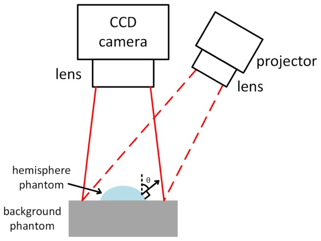
Diagram of angle θ in SFDI imaging geometry.
The proposed MLC method adds a coefficient k to the cosine term, as shown in Eq. (3). This coefficient accounts for the object-to-object diffuse reflectance (i.e. reflectance from an object’s background onto the object), and potentially other phenomenon not accounted for by the standard Lambertian method. When k is equal to 0, no angle correction occurs, and when k is 1, the MLC is equivalent to the standard Lambertian correction.
| (3) |
In order to find an appropriate coefficient k for each Mac map of an object-of-interest, we propose a parameter optimization method (Eq. (4). Note that for SFDI, there is a demodulated Mac map for each spatial frequency and wavelength, and the coefficient k is different for each demodulated map.
| (4) |
In Eq. (4), fx, θ, i, and n refer to spatial frequency, surface angle at the pixel location, pixel index, and total number of pixels in the optimization region of interest (ROI), respectively. The ROI (i.e. the tumor) is manually selected on the uncorrected Mac map. Mac, ref is the average Mac value of the low-angle areas with ≤10° thresholding within the ROI. It is used as a “gold standard” Mac for the minimization. In a practical sense, the low-angle area is a region of the ROI where surface angle effects are minimal. The parameter optimization will find the k value that minimizes the difference between MLC-corrected Mac and Mac, ref for the ROI. The optimization is solved using Newton’s method [21]. The determined k value is then applied to all pixels on the object to get the corrected Mac map. A different k value is determined for each spatial frequency and wavelength. The corrected Mac maps are used to calculate diffuse reflectance maps (Eq. (1), from which optical properties and chromophores are determined using Monte-Carlo look-up table method and linear fitting, respectively.
2.4. Experimental validation
The OxImager RS SFDI system (Modulated Imaging Inc., Irvine, CA) was used for all optical measurements in this study. This system provides LED illumination at up to 11 wavelengths spanning the visible to NIR and images with a 15 cm × 20 cm field of view. Height correction is applied in data processing [17]. SFDI measurements were taken at 526 nm and 659 nm for phantom studies, and a series of spatial frequencies were used: 0, 0.05, 0.1, 0.15, 0.2, 0.3, and 0.5 mm−1. The integration time of each image is adjusted from tens to hundreds of milliseconds to utilize the dynamic range of the camera.
Non-angle corrected, standard Lambertian, and MLC angle corrected SFDI measurements were compared using a set of hemisphere tissue-simulating optical phantoms. The hemispheres were fabricated using silicone as base solvent, Nigrosin as absorber, and titanium dioxide (TiO2) as scatterer. Hemispheres were made with diameters of 1 cm, 2 cm, or 3 cm. These diameters were chosen to mimic the expected range of preclinical xenograft tumors. The maximum surface normal angle of the hemispheres was 75°. Hemispheres were made with a range of optical properties; each phantom was homogenous. The optical properties of the phantoms were adjusted by varying the amount of absorbers and scatterers.
First, the effect of different k coefficients on demodulated Mac values for measurements on the hemispheres were compared over a line profile taken through the center of the hemisphere. Then, the relationship between spatial frequency and optimized k values was explored for hemispheres of different sizes, optical properties, and for different background phantoms. Then, the root-mean-square-errors (RMSE) of extracted µa and µs` were compared for non-angle, standard Lambertian, and MLC correction methods for all hemispheres. Errors were compared over a small angle range (<40°), which matches the reported range for the standard Lambertian correction [17], as well as for the full angle range (up to 75°). For RMSE calculations, calculations were done using all pixels within the angle range being analyzed.
The angle correction methods were also compared on a mouse tumor model. A malignant glioma cell line (GBM34-Lum) were injected subcutaneously on the flank of a nude mouse. The tumor was treated with combination of temozolomide and the anti-angiogenic bevacizumab. The mouse was measured with SFDI under isofluorane anesthesia, 4 days after the end of a treatment session, with a tumor size of 11.6 mm × 10.5 mm. The mouse was measured at 659 nm, 691 nm, 731 nm, and 851 nm illumination and tumor optical absorption and reduced scattering was extracted at these wavelengths. Tissue-level chromophore concentrations, including oxy and deoxyhemoglobin, were calculated using the extracted optical absorption by linear fitting. All animal procedures were approved by the Brigham and Women’s Hospital Animal Care and Use Committee.
3. Results
3.1. Optical properties of fabricated hemisphere phantoms
Figure 2 shows white light images and optical properties (at 526nm) of the 2 cm diameter hemisphere phantoms. Their optical properties at 526 nm and 659 nm are shown in Table 1. The 1 cm and 3 cm diameter hemispheres were made from the same phantom batch and had closely matching optical properties.
Fig. 2.
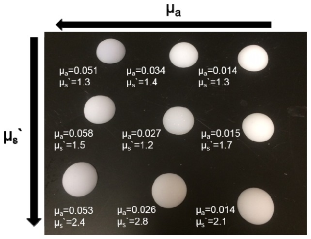
White light image of the 2 cm diameter hemisphere phantoms. Optical properties are shown for 526 nm.
Table 1. Optical properties of the 2 cm diameter hemisphere phantoms. 1 cm and 3 cm hemispheres were fabricated from the same batch and had closely matching optical properties.
| λ | Hemisphere | #1 | #2 | #3 | #4 | #5 | #6 | #7 | #8 | #9 |
|---|---|---|---|---|---|---|---|---|---|---|
| 526 nm | µa (mm−1) | 0.014 | 0.015 | 0.014 | 0.027 | 0.034 | 0.026 | 0.051 | 0.058 | 0.053 |
| µs` (mm−1) | 1.3 | 1.7 | 2.1 | 1.2 | 1.4 | 2.8 | 1.3 | 1.5 | 2.4 | |
| 659 nm | µa (mm−1) | 0.019 | 0.020 | 0.019 | 0.037 | 0.032 | 0.036 | 0.066 | 0.069 | 0.068 |
| µs` (mm−1) | 0.90 | 1.4 | 1.6 | 0.88 | 1.0 | 2.2 | 0.97 | 1.3 | 1.9 |
3.2. Mac line profiles for varied k coefficients
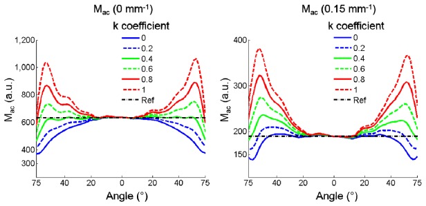
The effect on angle corrected demodulated image data with different MLC k coefficients was first explored on hemispheric phantoms. Figure 3 shows the line profiles of demodulated image data through the center of a 2 cm diameter optically diffusive homogeneous hemisphere phantom measured at 526 nm with optical properties of µa = 0.014 mm−1 and µs` = 1.3 mm−1. The hemisphere was imaged on a flat background phantom with optical properties of µa = 0.053 mm−1 and µs` = 1.2 mm−1. The left subfigure corresponds to SFDI data collected at 0 mm−1 spatial frequency (i.e. DC), whereas the right subfigure corresponds to 0.15 mm−1. The dashed black line in the figure represents the expected Mac value (i.e. the “gold standard” value) determined by the average Mac of the low-angle areas with ≤10° thresholding. The colored lines correspond to angle-corrected data with different k coefficient values ranging from 0 to 1.
Fig. 3.
Angle-corrected Mac versus coefficient k.
The solid blue line represents the demodulated intensity without any angle correction (k = 0). For the 0 mm−1 spatial frequency (Fig. 3, Left), Mac values are increasingly under-reported as the hemisphere surface normal angle increases from 0° (the center of the hemisphere) to 75° (the distal edge of the hemisphere). The red dashed line shows Lambertian correction (k = 1), which substantially over-corrects the demodulated intensity. For the higher spatial frequency, 0.15 mm−1 (Fig. 3, Right), non-angle corrected (k = 0) provides a better match to the expected Mac than Lambertian correction (k = 1) or other non-zero k values. In general, Fig. 3 visually supports the idea that some ideal k coefficient exists, which is spatial frequency dependent, which can minimize angle artifacts for homogenous hemispheric phantoms.
3.3. k coefficient determined by parameter optimization
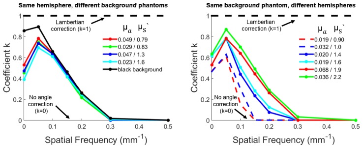
The effect of spatial frequency and object (hemisphere) and background optical properties on the choice of k coefficient was explored. Figure 4 shows the MLC coefficient k for a range of spatial frequencies determined by the parameter optimization. For the left subfigure, a 2 cm diameter hemisphere phantom (µa = 0.068 mm−1, µs` = 1.9 mm−1) was placed on five background phantoms with different optical properties. Each combination was measured with SFDI at 659 nm. Each line in the left subfigure represents a distinct background optical phantom whose optical properties are listed in the legend. The solid blackline represents a black background phantom, which has strong absorption and little scattering. The left subfigure shows that the coefficient k approaches 0 at higher spatial frequencies regardless of the optical properties of the background phantom. With a black background, k approaches 1 (Lambertian correction) for low spatial frequencies. For the right subfigure, six 2 cm diameter hemisphere phantoms with different optical properties were measured on the same background phantom (µa = 0.053 mm−1, µs` = 1.2 mm−1). Figure 4 shows that higher overall hemisphere optical attenuation requires higher k values and that k values are dependent on object optical properties and imaging spatial frequency.
Fig. 4.
Coefficient k versus spatial frequency.
3.4. Comparison of non-angle, standard Lambertian, and MLC on hemisphere phantoms
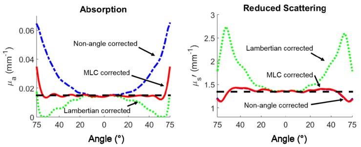
Comparisons were made between errors in optical property extractions for non-angle, standard Lambertian, and the MLC method. Figure 5 shows the line profiles of the absorption and reduced scattering through the center of a 2 cm diameter hemisphere placed on a background phantom (µa = 0.053 mm−1, µs` = 1.2 mm−1) measured at 526 nm. The dashed black line represents the expected µa / µs` values (“gold standard”). The dashed blue line, dashed green line, and solid red line correspond to non-angle, standard Lambertian, and MLC corrected µa / µs` data, respectively. For absorption, non-angle correction leads to overestimation of µa, while the Lambertian correction underestimates µa, causing it to be near 0 at the edges of the hemisphere (high angle areas). The MLC corrected µa is very close to the gold standard, outperforming the other two methods. For the reduced scattering, the non-angle correction and MLC are nearly identical, and both outperform standard Lambertian.
Fig. 5.
Line profiles of absorption and reduced scattering through the center of a 2 cm diameter hemisphere using different angle correction methods.
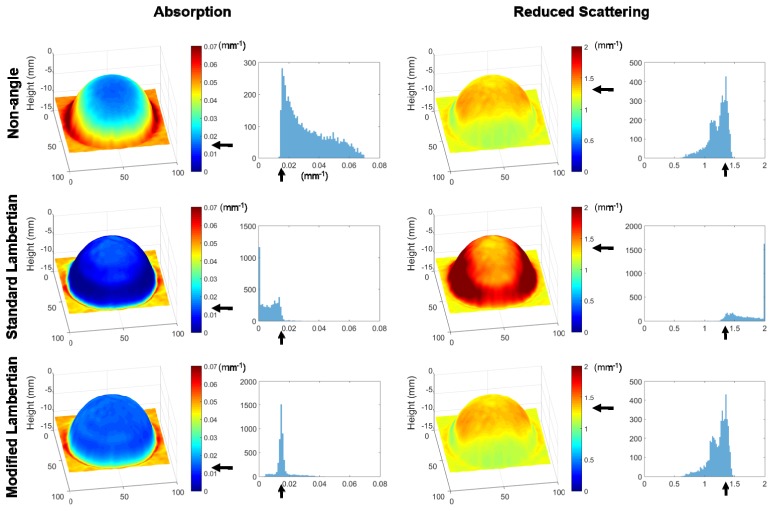
Figure 6 shows 3D absorption and reduced scattering maps rendered for the same hemisphere and background phantom. The black arrows indicate the “gold standard” µa / µs` values. The 3D visualizations and histograms demonstrate that non-angle corrected data skews towards µa values higher than the known value at high angles, and the standard Lambertian correction skews towards lower µa values at high angles. Lambertian correction also overestimates µs` at high angles, whereas MLC gives µa and µs` values that are close to the “gold standard”. It is of note that standard Lambertian correction produces a substantial number of pixels with µa values close to 0 mm−1, and µs` values close to 2 mm−1, the upper limit of displayed values. In contrast, the MLC data have a tighter distribution around the gold standard values, with modest µa underestimates at the extreme hemisphere edge.
Fig. 6.
Absorption and reduced scattering plots rendered with 3D heights, and histograms of the hemisphere region. Optical properties are shown for a 2 cm diameter hemisphere at 526 nm.
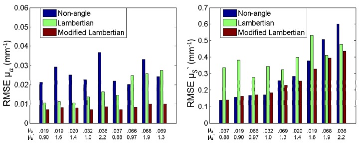
To quantitatively compare non-angle, standard Lambertian, and MLC correction methods, groups of hemisphere phantoms with different sizes and optical properties were measured at 526 nm and 659 nm. Their µa and µs` values were extracted, the three correction methods were applied, and the root-mean-square-errors (RMSE) were calculated for both low angles (<40°), and higher angles (up to 75°). Representative RMSE values for the larger angle range (up to 75°) are shown in Fig. 7. Values are plotted as bar plots representing the error between the known optical properties and the corrected optical properties over the entire hemisphere. This group has nine middle size hemisphere phantoms (2 cm diameter), measured at 659 nm. The average µa RMSE of non-angle, standard Lambertian, and MLC of this group was 0.026, 0.017, and 0.008 mm−1, respectively. For µs` the average RMSE for the three methods was 0.295, 0.387, and 0.256 mm−1, respectively. The MLC method reduces the µa RMSE by 68.9% and 52.4% respectively over non-angle and standard Lambertian correction, and reduces the µs` RMSE by 13.2% and 33.9% respectively.
Fig. 7.
RMSE bar plots of 2 cm diameter hemisphere phantoms, measured at 659 nm.
Comparing the three methods for angles less than 40° across all hemispheres (n = 27) and background phantoms (n = 5), the overall average µa RMSE of non-angle, standard Lambertian, and MLC was 0.0094, 0.0063, and 0.0052 mm−1, respectively. For µs` the overall average RMSE for the three methods for angles less than 40° was 0.16, 0.20, and 0.15 mm−1, respectively. These results demonstrate improved but comparable error levels for the standard Lambertian and MLC methods for smaller angles.
The overall average µa RMSE for angles up to 75° across all hemispheres was 0.029, 0.019, and 0.010 mm−1, respectively. For µs` the overall average RMSE for the three methods was 0.250, 0.454, and 0.209 mm−1, respectively. On average, the MLC method reduces the µa RMSE by 63.7% and 49.9% respectively over non-angle and standard Lambertian correction, and reduces the µs` RMSE by 15.9% and 51.9% respectively. In general, data from all measured hemispheres revealed that the MLC method greatly improved µa extractions over the other two methods for larger angles. For µs`, MLC did little to improve non-angle correction, but as expected, outperformed standard Lambertian correction which is not valid at angles higher than 40°.
3.5. Comparison of non-angle, standard Lambertian, and MLC on live mouse tumors
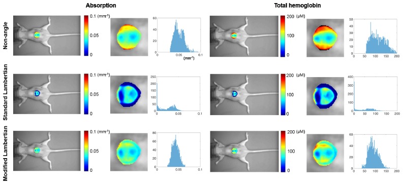
Figure 8 compares non-angle, standard Lambertian, and MLC on a live mouse tumor model. The µa and total hemoglobin concentration were extracted using the three methods respectively. The extracted tumor data distributions are also presented in the histograms. For non-angle correction, the tumor absorption values skew higher on the edges (high angles), with corresponding higher estimated total hemoglobin concentrations. For standard Lambertian correction, a perimeter at the base of the tumor has 0 mm−1 µa values, with corresponding 0 µM total hemoglobin values at these areas. Although “gold standard” values are not available for the mouse tumor, the extracted data distributions are tighter with the MLC method, and µa and total hemoglobin values are physiologically plausible throughout the tumor ROI.
Fig. 8.
Comparison of three methods on mouse tumor data and their distributions shown in histograms, measured at 659nm, 691 nm, 731 nm, and 851 nm. The plotted absorption data was measured at 659 nm. Optical properties are only shown for the tumor ROI. Zoomed-in figures are shown for the tumor optical absorption and total hemoglobin.
4. Discussion and conclusion
MLC correction for SFDI reduced µa extraction errors over a range of phantom hemisphere dimensions and optical properties by an average of 63.7% compared to performing no angle correction. Additionally, in contrast to non-angle correction and standard Lambertian correction, MLC produced optical property and chromophore extractions that better match physiologically reasonable values on a xenograft mouse tumor model, especially at the tumor edge. The empirical approach taken here to determine k requires measurement of surface angle, but does not require explicit knowledge, measurement, or input of background optical properties or instrument geometry, allowing it to be practically implemented in tumor monitoring studies regardless of specific instrument used and with little additional analysis effort.
The experiments performed in this study revealed that angle related effects in SFDI are dependent on the optical properties of the object of interest and background, the spatial frequency, the wavelength, and the imaging surface normal angle. For example, it was demonstrated that lower k values are required at high spatial frequencies, and almost no angle correction (k = 0) was required for spatial frequencies of 0.3 mm−1 and above. This suggests that data collected at higher spatial frequencies are less affected by both Lambertian effects and inter-object reflections. Since higher spatial frequencies are preferentially sensitive to tissue optical scattering [2,22], µs` data is preserved even without angle correction (i.e. k = 0), which was demonstrated by the relatively low RMSE values observed in scattering data when no angle correction was used. At DC, greater correction was required and k approached 1 (i.e. Lambertian correction) when the diffusive phantom was imaged on a dark, highly absorbing background. When hemisphere phantoms were imaged on a diffuse background, intermediate correction (i.e. 0 < k < 1) was required as the standard Lambertian correction significantly overcorrected Rd values for surfaces at higher angles. This is likely due to the inter-object reflections occurring between the background phantom and the hemisphere, which increase measured light intensity at the hemisphere edge. These angle dependent inter-object reflections have previously been described in the context of correcting satellite imagery [19]. At low AC spatial frequencies (e.g. 0.05 mm−1), higher k-values were needed, suggesting that Lambertian effects dominate. Although not explicitly explored in this work, effects related to the increase in projected imaging spatial frequency on the highly curved surfaces likely contribute to edge effects.
There are several limitations of the MLC correction method related to the assumptions required for its implementation. For example, the MLC method assumes that the Mac value of low-angle areas are representative of the entire region or object-of-interest, and large heterogeneities are likely to introduce errors. Specifically, under scenarios where low angle zones are not available or there are large inherent heterogeneities, the optimization could be invalid. Despite this limitation, MLC provided better optical property and chromophore extractions on actual tumors compared to non-angle or standard Lambertian corrections at the tumor edge. Another limitation is that the hemisphere phantoms tested here were fabricated with a maximum 75° surface normal relative the vertical since the angle dependence relationship of Rd above 75° deviated from the relationship observed below 75°, possible because of noise in the optical profilometry data or due to more complex interobject effects. It is of note that the mouse tumors imaged for this study had almost no pixels >75°, suggesting this may not be a limiting factor for small animal tumor imaging. Finally, MLC was only tested for a limited set of geometric shapes, and the method was tested only for corrections on a limited region-of-interest within the field-of-view (i.e. the tumor).
In the future, MLC will be tested for its ability to correct optical property extractions from more complex object geometries with spatially varying optical properties (i.e. an entire mouse). This is likely to require spatially varying k values, although the general trends observed in this study relating k to object and background optically properties and spatial frequency may allow for simpler implementations under constrained conditions, such as a limited range of optical properties throughout the field-of-view and known background optical properties.
The MLC method described here is likely to be useful for small animal tumor imaging as it provides a relatively simple method to recover high-angle data that would otherwise have to be censored from the data set. The application of MLC to SFDI for longitudinal drug response studies in subcutaneous mouse tumor models may allow for the identification of prognostic optical biomarkers of therapy response and resistance that can then be translated to in vivo human imaging using SFDI and other diffuse optical imaging technologies.
Acknowledgments
The authors wish to thank Irving Bigio, Amaan Mazhar, and David Cuccia for their helpful discussions. The authors gratefully acknowledge funding from the American Cancer Society (Grant RSG-14-014-01-CCE), the Department of Defense (Award No. W81XWH-15-1-0070) and the Boston University/Brigham and Women’s Hospital Collaborative Pilot Grant.
References and links
- 1.Cuccia D. J., Bevilacqua F., Durkin A. J., Tromberg B. J., “Modulated imaging: quantitative analysis and tomography of turbid media in the spatial-frequency domain,” Opt. Lett. 30(11), 1354–1356 (2005). 10.1364/OL.30.001354 [DOI] [PubMed] [Google Scholar]
- 2.Cuccia D. J., Bevilacqua F., Durkin A. J., Ayers F. R., Tromberg B. J., “Quantitation and mapping of tissue optical properties using modulated imaging,” J. Biomed. Opt. 14(2), 024012 (2009). 10.1117/1.3088140 [DOI] [PMC free article] [PubMed] [Google Scholar]
- 3.Sharif S. A., Taydas E., Mazhar A., Rahimian R., Kelly K. M., Choi B., Durkin A. J., “Noninvasive clinical assessment of port-wine stain birthmarks using current and future optical imaging technology: A review,” Br. J. Dermatol. 167(6), 1215–1223 (2012). 10.1111/j.1365-2133.2012.11139.x [DOI] [PMC free article] [PubMed] [Google Scholar]
- 4.Gioux S., Mazhar A., Lee B. T., Cuccia D. J., Stockdale A., Oketokoun R., Ashitate Y., Durr N., Durkin A. J., Tromberg B. J., Frangioni J. V., “Preclinical and clinical validation of a novel oxygenation imaging system,” Spectroscopy (Springf.) 7896, 78961R (2011). [Google Scholar]
- 5.Mazhar A., Sharif S., Saggese S., Choi B., Cuccia D. J., Durkin A. J., “Implementation of an LED based Clinical Spatial Frequency Domain Imaging System,” Proc. SPIE 8254, 82540A (2012). 10.1117/12.909813 [DOI] [Google Scholar]
- 6.Rohrbach D. J., Muffoletto D., Huihui J., Saager R., Keymel K., Paquette A., Morgan J., Zeitouni N., Sunar U., “Preoperative mapping of nonmelanoma skin cancer using spatial frequency domain and ultrasound imaging,” Acad. Radiol. 21(2), 263–270 (2014). 10.1016/j.acra.2013.11.013 [DOI] [PMC free article] [PubMed] [Google Scholar]
- 7.Nadeau K. P., Khoury P., Mazhar A., Cuccia D., Durkin J., “Component and system evaluation for the development of a handheld point-of-care spatial frequency domain imaging (SFDI) device,” Proc. SPIE 8573, 857304 (2013). 10.1117/12.2004909 [DOI] [Google Scholar]
- 8.Saager R. B., Cuccia D. J., Saggese S., Kelly K. M., Durkin A. J., “Quantitative fluorescence imaging of protoporphyrin IX through determination of tissue optical properties in the spatial frequency domain,” J. Biomed. Opt. 16(12), 126013 (2011). 10.1117/1.3665440 [DOI] [PMC free article] [PubMed] [Google Scholar]
- 9.Konecky S. D., Mazhar A., Cuccia D., Durkin A. J., Schotland J. C., Tromberg B. J., “Quantitative optical tomography of sub-surface heterogeneities using spatially modulated structured light,” Opt. Express 17(17), 14780–14790 (2009). 10.1364/OE.17.014780 [DOI] [PMC free article] [PubMed] [Google Scholar]
- 10.Konecky S. D., Owen C. M., Rice T., Valdés P. A., Kolste K., Wilson B. C., Leblond F., Roberts D. W., Paulsen K. D., Tromberg B. J., “Spatial frequency domain tomography of protoporphyrin IX fluorescence in preclinical glioma models,” J. Biomed. Opt. 17(5), 056008 (2012). 10.1117/1.JBO.17.5.056008 [DOI] [PMC free article] [PubMed] [Google Scholar]
- 11.Zhao Y., Roblyer D., “Spatial mapping of fluorophore quantum yield in diffusive media,” J. Biomed. Opt. 20(8), 086013 (2015). 10.1117/1.JBO.20.8.086013 [DOI] [PubMed] [Google Scholar]
- 12.Diep P., Pannem S., Sweer J., Lo J., Snyder M., Stueber G., Zhao Y., Tabassum S., Istfan R., Wu J., Erramilli S., Roblyer D., “Three-dimensional printed optical phantoms with customized absorption and scattering properties,” Biomed. Opt. Express 6(11), 4212–4220 (2015). 10.1364/BOE.6.004212 [DOI] [PMC free article] [PubMed] [Google Scholar]
- 13.Ponticorvo A., Burmeister D. M., Yang B., Choi B., Christy R. J., Durkin A. J., “Quantitative assessment of graded burn wounds in a porcine model using spatial frequency domain imaging (SFDI) and laser speckle imaging (LSI),” Biomed. Opt. Express 5(10), 3467–3481 (2014). 10.1364/BOE.5.003467 [DOI] [PMC free article] [PubMed] [Google Scholar]
- 14.Nguyen J. Q., Crouzet C., Mai T., Riola K., Uchitel D., Liaw L.-H., Bernal N., Ponticorvo A., Choi B., Durkin A. J., “Spatial frequency domain imaging of burn wounds in a preclinical model of graded burn severity,” J. Biomed. Opt. 18(6), 066010 (2013). 10.1117/1.JBO.18.6.066010 [DOI] [PMC free article] [PubMed] [Google Scholar]
- 15.Gioux S., Mazhar A., Lee B. T., Lin S. J., Tobias A. M., Cuccia D. J., Stockdale A., Oketokoun R., Ashitate Y., Kelly E., Weinmann M., Durr N. J., Moffitt L. A., Durkin A. J., Tromberg B. J., Frangioni J. V., “First-in-human pilot study of a spatial frequency domain oxygenation imaging system,” J. Biomed. Opt. 16(8), 086015 (2011). 10.1117/1.3614566 [DOI] [PMC free article] [PubMed] [Google Scholar]
- 16.Mazhar A., Saggese S., Pollins A. C., Cardwell N. L., Nanney L., Cuccia D. J., “Noncontact imaging of burn depth and extent in a porcine model using spatial frequency domain imaging,” J. Biomed. Opt. 19(8), 086019 (2014). 10.1117/1.JBO.19.8.086019 [DOI] [PMC free article] [PubMed] [Google Scholar]
- 17.Gioux S., Mazhar A., Cuccia D. J., Durkin A. J., Tromberg B. J., Frangioni J. V., “Three-dimensional surface profile intensity correction for spatially modulated imaging,” J. Biomed. Opt. 14(3), 034045 (2009). 10.1117/1.3156840 [DOI] [PMC free article] [PubMed] [Google Scholar]
- 18.Minnaert M., “The reciprocity principle in lunar photometry,” Astrophys. J. 93, 403 (1941). 10.1086/144279 [DOI] [Google Scholar]
- 19.Ekstrand S., “Landsat TM-Based Forest Damage Assessment: Correction for Topographic Effects,” Photogramm. Eng. Remote Sensing 62(2), 151–161 (1996). [Google Scholar]
- 20.Martinelli M., Gardner A., Cuccia D., Hayakawa C., Spanier J., Venugopalan V., “Analysis of single Monte Carlo methods for prediction of reflectance from turbid media,” Opt. Express 19(20), 19627–19642 (2011). 10.1364/OE.19.019627 [DOI] [PMC free article] [PubMed] [Google Scholar]
- 21.Boyd S., Vandenberghe L., Convex Optimization. Cambridge University Press, 2004. [Google Scholar]
- 22.McClatchy D. M., Krishnaswamy V., Kanick S. C., Elliott J. T., Wells W. A., Barth R. J., Paulsen K. D., Pogue B. W., “ High spatial frequency structured light imaging for intraoperative breast tumor margin assessment, ” vol. 9313, pp. 931304–931308, 2015. [Google Scholar]


