Abstract
Hybrid inorganic-organic perovskites have proven to be a revolutionary material for low-cost photovoltaic applications. They also exhibit many other interesting properties, including giant Rashba splitting, large-radius Wannier excitons, and novel magneto-optical effects. Understanding these properties as well as the detailed mechanism of photovoltaics requires a reliable and accessible electronic structure, on which models of transport, excitonic, and magneto-optical properties can be efficiently developed. Here we construct an effective-mass model for the hybrid perovskites based on the group theory, experiment, and first-principles calculations. Using this model, we relate the Rashba splitting with the inversion-asymmetry parameter in the tetragonal perovskites, evaluate anisotropic g-factors for both conduction and valence bands, and elucidate the magnetic-field effect on photoluminescence and its dependence on the intensity of photoexcitation. The diamagnetic effect of exciton is calculated for an arbitrarily strong magnetic field. The pronounced excitonic peak emerged at intermediate magnetic fields in cyclotron resonance is assigned to the 3D±2 states, whose splitting can be used to estimate the difference in the effective masses of electron and hole.
Hybrid organic-inorganic perovskites such as CH3NH3PbI3 represents a revolutionary breakthrough for low-cost solar cells1,2,3,4 because of their desirable optical and carrier transport properties5,6. The materials also exhibit many intriguing features, including strong spin-orbit coupling7 and the associated Rashba effect8,9, large-radius Wannier excitons10, and novel magnetic-field effect (MFE) in photoluminescence (PL) and photoconduction11,12, and show promise in light-emitting13 and thermoelectric14 applications.
These outstanding properties are interconnected and are ultimately determined by the material’s unusual electronic structure, which has been intensively studied by a variety of density-functional calculations15,16,17. While such first-principles calculations are indispensable in predicting the crystal structure, carrier effective mass, and band gap, they become increasingly unwieldy in studying processes involving excited states and under external fields. An alternative is to develop an effective-mass Hamiltonian18,19,20, which is both tractable and transparent in physics with parameters determined by experimentally measured properties. These properties, such as effective masses and g-factors, are usually obtained from magneto-optical studies, which turn out to be a major experimental means of validating the principle of the band theory of semiconductors.
Exciton, an electron-hole pair bounded by the Coulomb interaction, is a fundamental excitation in semiconductors. The exciton binding energy in the hybrid perovskites is critical to photovoltaic and light-emitting efficiencies and has been a subject of intense debate21,22. This controversy can be resolved via a definitive measurement of magneto-optical absorption (cyclotron resonance)23, which reveals characters of exciton as well as constituent electron and hole. To take advantage of the wealth of information, a detailed analysis of cyclotron resonance is needed. While diamagnetic response of an exciton is similar to that of a hydrogen, a key difference is that the electron and hole in an exciton have a comparable effective mass, particularly in the hybrid perovskites.
A moderate magnetic field less than 1 T is found to be able to influence exciton PL in CH3NH3PbI311,12, indicating that magnetic field is a versatile tool for studying excitons and free carriers. This MFE has been attributed to the Δg (the difference between electron and hole g-factors) mechanism, frequently encountered in organic radical pairs24. However, the lack of knowledge on the g-factors in CH3NH3PbI3 hampers the development of a clear understanding of the MFE. In addition, the MFE is sensitive to the intensity of photoexcitation12, which is not well understood.
Here we construct an effective-mass model of CH3NH3PbI3 based on information available in literature. This model, which can be extended to other hybrid perovskites by using suitable parameters, reveals connections among the g-factors, effective masses, and Rashba spin splittings. Using this model, we examine the MFE on exciton PL and find that the MFE is controlled by the interplay of exchange energy, exciton (spin) relaxation time, and the Zeeman energy. Besides the Δg mechanism, a Σg (summation of the electron and hole g-factors) mechanism can manifest itself in the MFE. The dependence of MFE on the intensity of photoexcitations is quantitatively explained in terms of the screening effect by the photogenerated carriers, which greatly reduces the exchange coupling of excitons. The diamagnetic effect on excitons under an arbitrarily large magnetic field is reliably calculated and in an excellent agreement with recent cyclotron measurements. The experimentally observed pronounced excitonic absorption peak, induced by the magnetic-field, can be attributed to the 3D±2 states, whose energy splitting can be used to determine the difference in electron and hole effective masses. Our results demonstrate the efficacy of the effective-mass model in understanding magneto-optical properties and suggest it a foundation for systematically studying many other transport, optical, and spintronic processes in the hybrid perovskites.
Results
Model
Crystalline CH3NH3PbI3 can have the high-temperature α-phase with the pseudo cubic (Oh) symmetry, the intermediate-temperature β-phase with the tetragonal (C4v) symmetry, and the low-temperature orthorhombic γ phase. Phase transitions from high to low temperatures, being of group-subgroup type, take place at 333 K and 150 K, respectively25,26. We focus in this paper on the β-phase, which is also a good description of the approximately uniaxial γ-phase25. In the β-phase, PbI6 octahedra are misalign with the C-axis (symmetry axis of C4v), and the structure is noncentrosymmetric.
First-principle calculations indicate that the valence and conduction bands are mainly associated with cationic (Pb) s and p orbitals, respectively15,16,17,27, denoted as S, X, Y, and Z. The direct band gap is located at R point7, which has the same C4v symmetry as the crystal structure. Since physically relevant states are those close to the band extremes, we derive band structure in the neighborhood of R point, via the k · p method, where k is the wave vector away from the R point. In this method, the wave function at k is expressed as ψnk = eik·run(r) with un(r) being the basis function of nth band at the R point. We note that the k · p Hamiltonian for zinc-blende semiconductors is not suitable for the tetragonal perovskites15. In the absence of magnetic field, the Hamiltonian can be written as H = H0 + HSO, where H0 = p2/2 m + V(r) is spin-independent part and  is the spin-orbit coupling (SOC). Here V(r) is periodic potential, p is momentum, m is free electron mass, c is the speed of light, and σ are the Pauli matrices.
In the β-phase, the potential should be an identical representation of group C4v, a subgroup of the cubic group Oh, and therefore can be expressed in terms of the Oh representations, in particular, its first three irreducible representations, Γ1 ⊕ Γ12 ⊕ Γ15. Neglecting the trivial Γ1 representation, we write V(r) = ∑jcjdj, where d1 = 2z2 − x2 − y2 and d2 = x2 − y2 are the basis functions of Γ12, and d3 = x, d4 = y, and d5 = z are the basis functions of Γ15. By requiring D(Gi)V(r) = V(r) with Gi being the symmetry operators in C4v, c2 = c3 = c4 = 0. The nonzero c1 reflects a crystal-field splitting between Z and X (Y), 〈X|H0|X〉 = 〈Y|H0|Y〉 = −〈Z|H0|Z〉/2 = δ/3. And c5 originates from the lack of inversion asymmetry in C4v, giving rise to28 〈S|H0|Z〉 = 〈Z|H0|S〉* = c5〈S|z|Z〉 ≡ ζ.
The Hamiltonian H0, up to the second order of k, can be written as19,20
 |
Here Ev is the valence-band maximum, Li, Mi, and Ni are parameters due to the interaction between the conduction bands with far bands other than the valence band, and  and
and 
 are the Kane parameters that connect the valence-band and conduction-band orbitals20.
The SOC among the p orbitals mixes up and down spins, λ = i〈X↑|HSO|Y↓〉 = i〈Y↑|HSO|Z↓〉 = i〈Z↑|HSO|X↓〉, which is particularly strong in the hybrid perovskites due to the heavy element Pb, λ = 1.2–1.5 eV7,8,9, and cannot be treated as a perturbation.
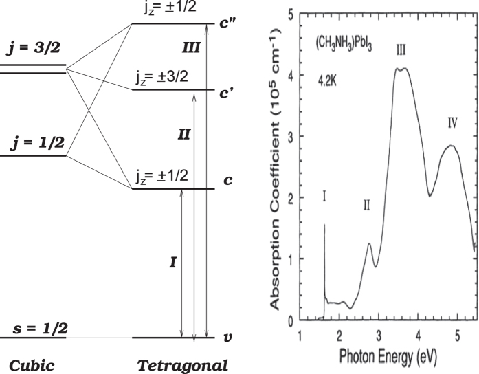
The crux of the k · p method is that the basis functions of un(r) should be the eigenstates of H at k = 020, which can be achieved by choosing the following basis functions un(r),
 |
 |
 |
 |
with  . The angular momentum is s = 1/2 for the valence band v±, and j = 1/2 (j = l + s with l = 1 and s = 1/2) for the first conduction band c±. The two upper conduction bands,
  , and
, and  , have j = 3/2, with jz = ±3/2 for
  and jz = ±1/2 for
  . The diagonal elements at k = 0 in these basis functions are Ev,
  , Ec′ = 0,
  . Here we temporally neglect ζ, which is small as compared to other parameters. In the measured absorption spectra of CH3NH3PbI3 (Fig. 1), the first three peaks, located at 1.6 eV, 2.8 eV, and 3.4 eV29, can be attributed to electron transitions from the valence band to the three conduction bands. Thus we obtain the values Ev = −2.8 eV, Ec = −1.2 eV, and Ec′ = 0.6 eV, which fix the parameter values, λ = 1.4 eV, δ = −0.7 eV, and sin ξ = 0.411.
Figure 1. Schematic diagram of band edges and their angular momenta in CH3NH3PbI3.
The optical absorption spectrum is adapted from ref. 29.
An applied magnetic field B have two effects on a charge carrier: paramagnetic magnetism due to the carrier’s spin and diamagnetic orbital magnetism due to the lack of commutation among momentum components,  30, where
  is the antisymmetric tensor of rank three. Because of the latter, the effective Zeeman energy of quasi-degenerate conduction-band orbitals can be written as
 |
where l (l = 1) is the angular momentum operator, and κ1 and κ2 are the Luttinger antisymmetric parameters for tetragonal structures.
The total Hamiltonian, in the presence of magnetic field B, can now be written as
 |
where 4 × 4 matrices HA, HB and HC are displayed in the Methods section. In this Hamiltonian, we have eleven parameters, Li and κi (i = 1, 2), Mi and Ni (i = 1, 2, 3),  , and P⊥. If the information at hand is insufficient to fix all these parameters, one can resort to the first principles calculations, or via the quasi-cubic symmetry, L1 = L2, M1 = M2 = M3, and κ1 = κ2.
g-factors, effective masses, and cyclotron frequencies
The most important transport and optical processes occur in the conduction and valence bands, which are both nondegenerate (excluding spin). We map the above 8 × 8 Hamiltonian Hmn into two effective 2 × 2 Hamiltonians in spin space for these two bands by employing the Löwdin method for degenerate perturbation theory31,
 |
Here Em(k) is the energy of mth band, which, for small k, can be approximated by the band-edge value. Taking into account the non-commutative relations among k components, we obtain the effective Hamiltonians, up to the second order of k, for the valence and conduction bands, with basis functions of v± and c± in Eqs (2) and (3),
 |
 |
where μB ≡ eħ/(2 mc) is the Bohr magneton,  and
and  , which can be approximated by Ev and Ec.
The effective masses of valence band along and perpendicular to the C-axis in Eq. (9) are expressed as
 |
It is interesting to note that mh|| (mh⊥) depends on the interaction with the conduction bands via the Kane parameter P|| (P⊥). Similarly, the effective masses of the conduction band along and perpendicular to the C-axis are
 |
which are influenced by the interaction with the valence band, as well as by the symmetric parameters Li and Mi, stemming from the interaction with far bands. The anisotropic effective masses for the valence and conduction bands have been extensively calculated by several first-principles approaches16,17. One of the most accurate values are given in ref. 17, which are also consistent with recent cyclotron resonance measurements23,  , mh⊥ = 0.23 m, me|| = 0.15 m, and me⊥ = 0.21 m. From these effective masses, we obtain the Kane parameters, P|| = 7.64 eV Å and P⊥ = 6.95 eV Å, as well as the symmetric parameters mLi/ħ2 = −25.90 and mMi/ħ2 = 23.39.
A free electron possesses a magnetic moment of its spin and has a g-factor of g0 = 2.0023. The SOC enables the electron orbital motion to contribute to the magnetic moment and, consequently, the effective g-factor deviates from g0. In Eq. (9), the g-factors of the valence-band edge along and perpendicular to the C-axis are
 |
 |
We see that the g-factors depend on the energies of conduction-band edges as well as the Kane parameters. In contrast to the effective mass, gh|| is connected to the conduction bands only via P⊥. This is understandable because a magnetic field B affects the electron orbital motion perpendicular to the field. For the same reason, gh⊥ is connected to the conduction bands via both P|| and P⊥. Using the values of P|| and P⊥, we obtain the gh|| = −0.472 and gh⊥ = −0.354, which are similar to the value in 2H-PbI2, gh = −0.432. The negative g-factor means that the up spin has a lower energy than the down spin.
The conduction-band g-factors along and perpendicular to the C-axis are
 |
 |
which depend on the antisymmetric Luttinger parameters κ1 and κ2, in addition to the  . Thus the values of ge|| and ge⊥ can be used to determine κ1 and κ2. Experimentally, the exciton g-factor are measured from the energy splitting between left- and right-circularly polarized absorption33,34 and PL11, which, as we will discuss below, is ge|| + gh||. If we use ge|| + gh|| = 1.2, as in ref. 33, we find ge|| = 1.672 and κ1 = 0.269. If we further assume κ2 = κ1, we have ge⊥ = 2.281. These values are also similar to those of electrons in 2H-PbI2, ge|| = 1.4 and ge⊥ = 2.432.
Since both the g-factors and the effective masses are anisotropic, the effective spin splitting and the cyclotron frequency depend on the angle θ between the magnetic field and the C-axis,
 |
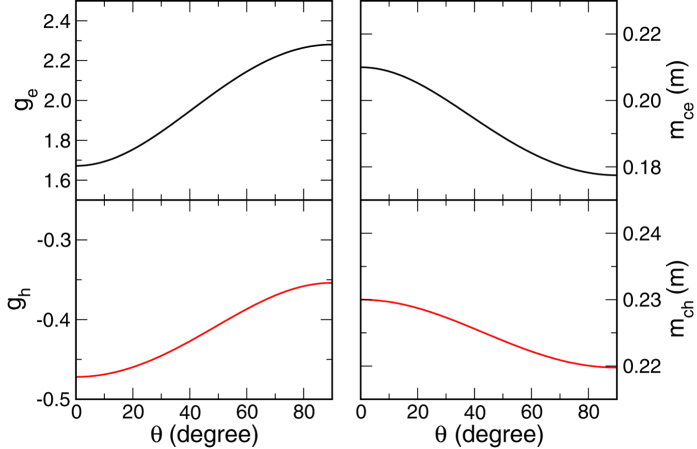
The derivations can be found in the Methods section. We plot in Fig. 2 the g-factors and the effective cyclotron mass,  as a function of θ. At θ = 0,
  and mce(h)(θ) = me(h)⊥. At θ = π/2, ge(h)(θ) = ge(h)⊥ and
  .
.
Figure 2. g-factors and cyclotron masses of conduction and valence bands.
Left panels describe the electron (ge) and hole (gh) g-factors as a function of angle θ between the C-axis and the applied magnetic field. Right panels describe the electron (mce) and hole (mch) cyclotron masses.
Rashba splitting
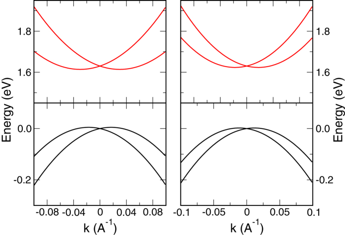
The Rashba term, Ec(v)r(k) = αc(v)r(kyσx − kxσy) in Eqs (9) and (10), destroys the spin degeneracy, giving rise to energy-momentum dispersions,  for the conduction band and
  for the valence band, as plotted in Fig. 3.
Figure 3. Rashba effect in the conduction and valence bands near the R point.
Left (right) panel is for k along the [0, 1, 1] ([0, 1, 1]) direction. ζ = 0.5 eV.
The Rashba strengths αc(v)r are directly related to the C4v potential ζ-parameter that characterizes the inversion asymmetry of the structure,
 |
 |
which indicate that the Rashba splittings in the valence and conduction bands are correlated. Currently the Rashba splittings obtained from different first-principles calculations vary significantly and direct measurements, such as spin-polarized photoemission and spin-flip Raman scattering, of CH3NH3PbI3 are not yet available. For ζ = 0.5 eV, we have αvr = 0.565 and αcr =1.088 eVÅ.
Exciton wavefunctions
Hybrid perovskite CH3NH3PbI3 has a large dielectric constant ε, and the excitons are of the Wannier type, whose wave functions can be written as35
 |
where je, jh = ±,  with
with  being the time-reversal operator.
  is the envelop function describing the relative motion of electron and hole and may have S, P, or D characteristics in low magnetic fields, which gradually transforms to that of Landau wave functions with increase of magnetic field.
The hole (electron) state 
 follows the
 representation of C4v. With
  being the 1S state, the exciton wavefuctions can be characterized by the C4v representations,
  ,
,
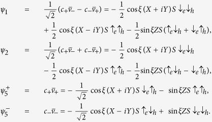 |
The total angular momentum J = je + jh is J = 0 for ψ1, (J, Jz) = (1, 0) for ψ2, and (J, Jz = 1, ±1) for  . The absorption and emission of these states are proportional to the modular square of their electric-dipole elements,
 |
with  . Hence ψ2 can absorb and emit light polarized along the z-axis, and
  can absorb and emit light circularly polarized in the x-y plane. ψ1, however, is dark, for it contains only spin triplets and is therefore dipole-forbidden.
The above selection rules in the hybrid perovskites is in stark contrast to those in π-conjugated organic materials with weak SOCs36, where the electron (hole) has zero angular momentum (lz = 0 for π orbitals) and J = 1 is dipole forbidden whereas J = 0 is dipole allowed. As we will see below, this difference gives rise to a far richer physics of MFE in the hybrid perovskites.
Paramagnetic effects on excitons
The four 1S exciton states, ψ1, ψ2, and  , in general, are not degenerate in energy because of possible exchange interaction between spins
  , where σe/2 = je and σh/2 = sh. Consequently the energies of these excitons
  .
.
An applied magnetic field can modify the exciton energy via the Zeeman energy,
 |
It should be noted that from the time reversal symmetry, the hole’s g-factor, including the sign, is identical to that of the valence electron. Since we are concerned with relatively weak magnetic field, we temporarily neglect the diamagnetic effect, which is proportional to B2 and shift states equally in energy.
In the Faraday configuration with B along the C-axis, B = (0, 0, B),  will split in energy,
 , and the splitting in absorption and luminescence peaks of left- and right-circularly polarized light, would be
  11,33,34.
The magnetic field B will also mix ψ1 and ψ2, with
 |
and the energies of eigenstates become  and their wave functions are
  (i = 1, 2). Hence, with increase of the magnetic field,
  will gain oscillator strength,
  , and flare up, while
  will lose oscillator strength,
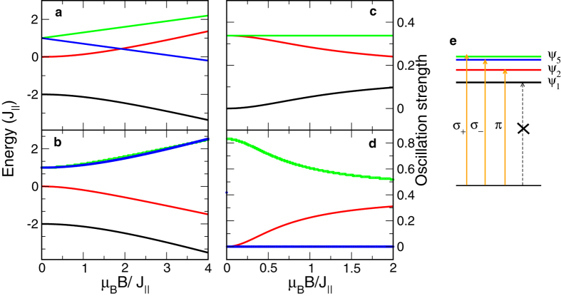
  , as illustrated in Fig. 4.
Figure 4. Exciton energies and oscillator strengths vs magnetic field.
Panels (a,b) delineate exciton energies as a function of magnetic field in the Faraday and Voigt configurations, respectively. Panels (c,d) are the oscillator strengths of these exciton states along the z-axis and the x-axis, respectively. Panel (e) illustrates the electric-dipole selection rule of the exciton states. Black and red lines correspond to ψ1 and ψ2 excitons. Green and blue lines correspond to  and
and  excitons in (a,c), and ψ5L and ψ5T in (c,d). Green and blue lines in (c) as well as black and blue lines in (d) are on top of each other.
  .
.
In the Vogit configuration with B perpendicular to the C-axis, B = (B, 0, 0), we can construct transverse and longitudinal states out of  states,
  and
and  , which have polarization along the y and x axis, respectively. It is readily to verify that in this configuration, pair (ψ1, ψ5L) as well as pair (ψ2, ψ5T) are coupled via the magnetic field, with
 |
 |
and their energies are  and
and 
 . Figure 4 also plots the exciton energies E1, E2, E5L, and E5T, as well as their corresponding oscillator strengths |〈ex px〉|2 as a function of the magnetic field.
Magnetic-field effect on photoluminescence
The PL intensity in CH3NH3PbI3 is found to be susceptible to a magnetic field at low temperatures11. In the Faraday configuration, the magnetic field couples ψ1 and ψ2 excitons. Since only the recombination of ψ2 can give rise to luminescence, the magnetic-field-induced change in populations of ψ2 and ψ1 would lead to an MFE. We employ the Bloch equation of the density matrix to systematically describe the population dynamics,
 |
where  is a 2 × 2 density matrix spanned by ψ1 and ψ2,
  with m, n = 1, 2. (∂ρ/∂t)g represents the generation of the exciton states, which is finite only for diagonal terms, (∂ρmn/∂t)g = Fmδmn, because the PL in the MFET measurements11,12 is not resonantly excited. τ is the relaxation time of these exciton states, which includes both recombination
  and spin relaxation
  ,
,  , for
, for  5,6,11. In the steady state,
  , the densities at ψ1 and ψ2 can be written as
  and
and  , where
  and
and  . The intensity change in PL is due to the change in ρ22,
 |
When the exchange is significant with  ,
,  with
with  . In this regime, the MFE is suppressed because the magnetic field cannot overcome the exchange to effectively alter the populations on the exciton states for H < 1T. When
  , the denominator in Eq. (24) becomes
  , which represents the so called Δg mechanism of MFE. The Δg mechanism has been found responsible for many MFE phenomena involving radical pairs in organic systems24. If the
  is known, the Lorentz line shape in Eq. (24) can be used to measure the exciton relaxation time τ, or equivalently, its spin relaxation time.
In the Vogit configuration, the MFE in PL is also expected because the magnetic field, as shown in Eqs (21) and (22), mixes the dark ψ1 with the dipole-allowed ψ5L, and ψ2 with ψ5T, which have different oscillator strengths and polarizations,  and along the z-axis and
  and along the y-axis for ψ5T, respectively. Using the Bloch equation, we express the PL change in the ψ1 and ψ5L manifold as
 |
where Δg⊥ = ge⊥ − gh⊥, and the PL change in the manifold of ψ2 and ψ5T as
 |
where Σg⊥ = ge⊥ + gh⊥. The MFE in the ψ1 and ψ5L manifold, ΔI2, depends on the difference in the g-factors along the x-axis, the direction of the magnetic field, in a very similar fashion as ΔI1.
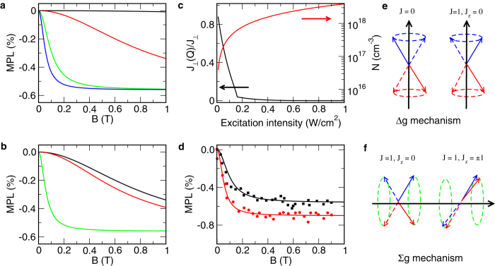
The MFE in the ψ2 and ψ5T manifold, ΔI3, however, depends on the summation of the electron and hole g-factors along the x-axis. Thus in addition to the Δg mechanism, a Σg mechanism is taking effect in the hybrid perovskites. In the former, the magnetic field modulates the populations between states J = 0 and (J, Jz(x)) = (1, 0), which can be visualized as the electron and hole spins precess along the magnetic field in the opposite directions. In the latter, the magnetic field modulates populations between (J, Jz) = (1, 0) and (1, ±1), which can be visualized as the electron and hole spins precess along a transverse magnetic field in the same direction. The Σg mechanism is particularly important if the exchange is approximately isotropic,  , where the J = 1 triplet states are degenerate in energy, and according Eq. (26), ΔI3 is then completely determined by the exciton relaxation time τ, whereas ΔI1 and ΔI2 in Eqs (24) and (25) are suppressed by the exchange splitting 4J⊥ between the singlet and triplet. For polycrystalline materials, the intensity change should be the combination of the three processes, ΔIi (i = 1, 2, 3), suggesting that multiple Lorentzen functions may be required to describe experimental data, as shown experimentally11.
Photoexcitation intensity dependence of MFE
It is observed that the MFE in PL in CH3NH3PbI3 is also dependent on the photoexcitation intensity12. Only when the intensity reaches a certain threshold, does the MFE become significant. The line shape of MFE shrinks with the increase of the photoexcitation intensity and is eventually stabilized. To explain this unusual intensity dependence, we notice that the MFE, as shown in Fig. 5, is pronounced only when the Zeeman energy dominates over the exchange splitting. As a specific example, we consider the Faraday configuration, where the energy splitting between ψ1 and ψ2 is 4J⊥. This exchange is of short-range and related to the exciton envelop function Φ(r) at r = 0, i.e., when the electron and hole are at the same location. For the 1S state,
Figure 5. Magnetic field effect in exciton photoluminescence.
Panel (a) describes ΔI1 for exchange splitting between ψ2 and ψ1 being 4J⊥ = 1 (black line), 0.1 (red line), 0.01 (green line), and 0.001(blue line) meV. Panel (b) describes ΔI1 (black line), ΔI2 (red line), and ΔI3 (green line) for  meV. Panel (c) describes the carrier density and the reduction of the exchange as a function of the intensity of excitation light. Panel (d) plots ΔI1 as a function of magnetic field with 4J⊥ = 1 meV for intensities of 0.34 (black line) and 0.85 W/cm2 (red line). Black and red dots are the corresponding experimental values in ref. 12. Panels (e,f) illustrate the Δg and Σg mechanisms. The exciton relaxation time is fixed at 10−10 s.
 |
where a0 is the effective Bohr radius of the exciton, a0 = ħ2ε/e2μ with  being the effective mass of exciton.
A high-intensity photoexcitation creates many free electron-hole pairs, whose density can be estimated as N = αIτl/ħω, where α is the absorption coefficient, α ~ 105 cm−1 5 for the CH3NH3PbI3, τl is the carrier recombination lifetime,  s, and ħω is the photon energy. These free electron-hole pairs will screen the Coulomb interaction, which can be modeled by the Debye-Hückel theory of ion gases37. The Coulomb potential −e2/εr, in the presence of charged particles, is replaced by the potential U that satisfies the Poisson equation, (∇2 − Q2)U = 0 with Q2 = 8πe2/kBTN. The solution U(r) is of the Yukawa type U(r) = −e2e−Qr/(εr), and the ground-state wave function in such a potential can be written as
  , where the trial parameter β can be obtained by minimizing the ground state energy of Hamiltonian −∇2/2μ + U(r), E = (1)/(2)β2Q2ħ2/μ − 4β3e2/[εQ(4β2 + 4β + 1)]. The wave function
  , as compared to Φ(r), is more spreaded in space, and the exchange will be reduced by a factor
 |
Figure 5 illustrates the screening effect. We see that as the intensity of photoexcitation increases, the exchange is greatly reduced. The MFE, meanwhile, becomes significant. After the carrier density reaches 1018 cm−3, the exchange is so small that  , and the line shape in ΔI1 is independent of exchange, and therefore the photoexcitation intensity.
Diamagnetic effect on excitons
So far we have considered only the 1S exciton states and neglected the diamagnetic effect on excitons. The diamagnetic effect originates from the orbital motions of electron and hole, and has been used to directly measure the exciton’s binding energy and effective mass23. For free electrons and holes, an applied magnetic field can localized their orbital wave function normal to the magnetic field, forming the Landau levels with the magnetic length of  . Since the anisotropy in effective mass for both electron and hole are relatively small, as shown in Fig. 2, we use isotropic effective masses,
  , mh =
 , and
, and  , to study the diamagnetic effect.
The diamagnetic response of excitons is far more complex than that of free electron-hole pairs, but offers more valuable information on excitons as well as constituent electrons and holes. Under a small magnetic field, the Coulomb interaction in an exciton is predominant and the diamagnetic effect can be studied by applying the perturbation theory to the hydrogen-like exciton wavefunctions. Such a perturbation must fail when the magnetic length  becomes much smaller than the orbital radius of exciton, a0 = ħ2ε/(e2μ). In this high-magnetic field regime, it is more appropriate to use the Landau levels as the starting point. A ratio, γ = ħωc/2Ry, between the exciton cyclotron energy ħωc = eB/(μc) and the exciton binding energy, Ry = μe4/(2ε2ħ2), can be used to distinguish the weak (γ < 1) and strong (γ > 1) magnetic-field regimes.
The Hamiltonian for the envelop function Φ(re − rh) at K = 0 (K being the center-of-mass momentum of exciton) reads
 |
where L = −ir × ∇ is the orbital angular momentum. While this Hamiltonian of exciton is similar as that of hydrogen atom in a magnetic field, the key difference is that the third term contains  , the difference between electron and hole effective masses, which will reduce to μ−1 in the hydrogen case.
To reliably solve the Hamiltonian for an arbitrary magnetic field, we employ two different basis sets38. In low magnetic fields, by using a0 (Ry) as the length (energy) scale,  , where η = m/me − m/mh and Ylm is spherical harmonic function. We choose the basis set as
 |
which are the eigenstates of  with
with  is the generalized Laguerre polynomials.
In high magnetic fields, by using  and
and  as the length and energy scales
 , and the eigenfunctions of a spherical harmonic oscillator H0 = −∇2 + r2
 |
with  are chosen to be another basis set. These basis sets, with correct characteristics of wave functions in the low- and high-field regimes, facilitate an analytical evaluation of the Hamiltonian matrix elements (see the Methods section). Moreover the basis sets are eigenstates of parity and Lz = m, which are good quantum numbers of the Hamiltonian. We use large basis sets in both regimes, n, l ≤ 20 for Φnlm and n, l ≤ 29 for Ψnlm, and diagonalize the Hamiltonian to obtain the eigenstates. The large basis sets allow us to approach the intermediate γ ~ 1 from both γ < 1 and γ > 1 regimes so that the solutions from both ends are smoothly connected. In the limit of γ → ∞, the eigenstates become the the Landau levels of free electron and hole.
  and
and  . The optical selection rule for the transition from valence- to conduction-band Landau levels is Nh = Ne = N, and the absorption peaks are located at
  , where Eg is the band gap.
In Fig. 6, we compare the theoretical results with recent cyclotron resonance experiment23, using the effective masses of mh = 0.223 m and me = 0.188 m, and the binding energy of 16 meV. The agreement between theory and experiment is excellent. In addition, the pronounced absorption peaks above the 2S state, induced by the magnetic field, are very close to the state 3D±2, whereas the 2P0 state, as assigned in ref. 23 for the absorption peak, is almost degenerate in energy with 2S state. Indeed, transitions to exciton states  and
and  , according to the selection rule, are electric-dipole allowed and the only reason that these the state is dark at zero field is Φ(r = 0) = 0, which become finite in large magnetic fields. Thus we believe that the observed excitonic absorption peak is due to the 3D±2 states. 3D±2 states are important in that from their energy splitting,
  , we can obtain the difference in the effective masses of electron and hole, which, together with μ measured from the Landau levels of free electron-hole absorption, can completely determine both me and mh. It is noted that the inter-band cyclotron resonance of free electron-hole pairs can measure only μ, not individual me and mh. Thus cyclotron resonance of excitons reveals more information.
Figure 6. Cyclotron resonance of excitons in CH3NH3PbI3.
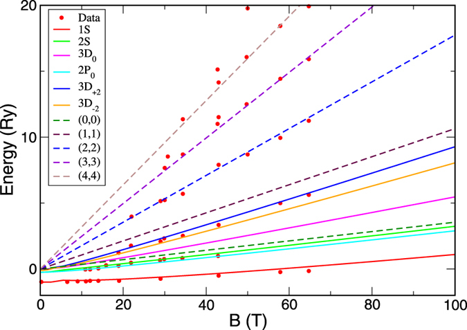
Solid lines are energies of different exciton states. Dashed lines are the energy difference between the Landau levels of free electron and holes with (N, N) being the Landau-level index. Dots are the experimental data from ref. 23. The absorption peak between 2S and (1, 1) coincides with the energies of 3D±2 states.
Discussion
The hybrid inorganic-organic perovskites have shown great promise in photovoltaic and many other important applications because of their outstanding transport, optical, and magneto-optical properties. To understand these properties, in this paper, we have constructed a reliable and accessible effective-mass model of the hybrid perovskites, which connects effective masses, Rashba splittings, and anisotropic g-factors of conduction and valence bands. Using this effective-mass model, we have elucidated the observed MFE in exciton PL and its dependence on photoexcitations and identified a new Σg mechanism of MFE. We have also calculated the cyclotron resonance of excitons for arbitrarily strong magnetic fields and pointed out that excitonic states such as 3D±2 provide information on the difference in effective masses of electron and hole.
This effective-mass model is a foundation on which systematic models of electron-phonon coupling, carrier mobility, and other transport properties can be developed. Because of the concise expressions of SOC, Rashba effect, and g-factor, this model also facilitates studies of spin relaxation39, spin Hall effect40, and other magneto optical and spintronic phenomena.
Methods
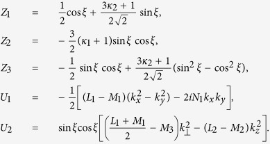
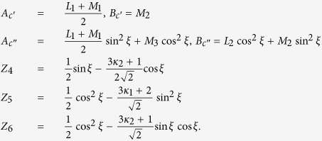
Expressions of H A, H B, and H C
The three 4 × 4 matrices in Eq. (7) are displayed as
 |
where
 |
 |
where
 |
 |
where
 |
Derivations of Eq. (15)
When the applied magnetic field B tilts away from the crystal C-axis with an angle θ, we can define the new z-axis (denoted z′) along B and assume that the tilting is in the x-z plane with the new x-axis denoted as x′. The transformations of coordinates between the two references are
 |
 |
The Zeeman energy in Eqs (9) and (10) then becomes
 |
and the effective g-factor g(θ) in Eq. (15) can be obtained by diagnonalizing this Hamiltonian.
In the new reference system,  , and the kinetic energy in Eqs (9) and (10) reads
 |
with  ,
, 
 ,
,  . We can define the ladder operators b and b+ of the Landau levels as
 |
with  , which satisfy [b, b+] = 1. The kinetic energy is then expressed as
 |
with  , which gives mc(θ) in Eq. (15).
Matrix elements of H D in basis sets of Φ nlm and Ψ nlm
The matrix elements of HD among Φnlm and among Ψnlm can be evaluated analytically, which greatly simplifies the eigenstate calculations.
The matrix element of angle-dependent term in the Hamiltonian can be calculated via the integral
 |
where the Wigner 3-j symbols are used.
The only type of matrix elements to be evaluated is rs between the basis functions. Between basis functions  and
and  ,
,
 |
The integral can be worked out analytically,
 |
where γ = li + lj + s + 2,  , α = 2li + 1, β = 2lj + 1, m = ni − li − 1, n = nj − lj − 1, λ = 2/nj, μ = 2/nj, and 2F1(α, β, γ; z is the Gauss’ hypergeometric function.
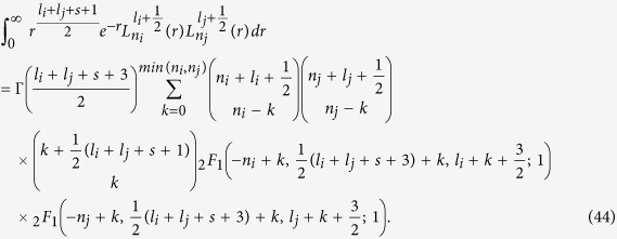
The matrix element of rs between basis functions  and
and  , neglecting the normalization factor, is
 |
Additional Information
How to cite this article: Yu, Z. G. Effective-mass model and magneto-optical properties in hybrid perovskites. Sci. Rep. 6, 28576; doi: 10.1038/srep28576 (2016).
Acknowledgments
I thank B. Hu, Y. Li, D. Sun, and Z. V. Vardeny for useful discussions. This work was partly supported by the US Army Research Office under Contract No. W911NF-15-1-0117.
Footnotes
Author Contributions Z.G.Y. conceived the concept, performed the calculations, analyzed the results and wrote the manuscript.
References
- Kojima A., Teshima K., Shirai Y. & Miyasaka T. Organometal halide perovskites as visible-light sensitizers for photovoltaic cells. J. Am. Chem. Soc. 131, 6050 (2009). [DOI] [PubMed] [Google Scholar]
- Etgar L. et al. Mesoscopic CH3NH3PbI3/TiO2 heterojunction solar cells. J. Am. Chem. Soc. 134 17396 (2012). [DOI] [PubMed] [Google Scholar]
- Burschka J. et al. Sequential deposition as a route to high-performance perovskite-sensitized solar cells. Nature 499, 316 (2013). [DOI] [PubMed] [Google Scholar]
- Lee M. M., Teuscher J., Miyasaka T., Murakami T. N. & Snaith H. J. Efficient hybrid solar cells based on meso-superstructured organometal halide perovskites. Science 338, 643 (2012). [DOI] [PubMed] [Google Scholar]
- Dong Q. et al. Electron-hole diffusion lengths >175 μm in solution-grown CH3NH3PbI3 single crystals. Science 347, 967 (2015). [DOI] [PubMed] [Google Scholar]
- Shi D. et al. Low trap-state density and long carrier diffusion in organolead trihalide perovskite single crystals. Science 347, 519 (2015). [DOI] [PubMed] [Google Scholar]
- Even J., Pedesseau L., Jancu J.-M. & Katan C. Importance of spin-orbit coupling in hybrid organic/inorganic perovskites for photovoltaic applications. J. Phys. Chem. Lett. 4, 2999 (2013). [Google Scholar]
- Jin H., Im J. & Freeman A. J. Topological insulator phase in halide perovskite structures. Phys. Rev. B 86, 121102(R) (2012). [Google Scholar]
- Kim M., Im J., Freeman A. J., Ihm J. & Jin H. Switchable S = 1/2 and J = 1/2 Rashba bands in ferroelectric halide perovskites. Proc. Natl. Acad. Sci. USA 111, 6900 (2014). [DOI] [PMC free article] [PubMed] [Google Scholar]
- Ishihara T., Takahashi J. & Goto T. Optical properties due to electronic transitions in two-dimensional semiconductors (CnH2n+1NH3)2PbI4. Phys. Rev. B 42, 11099 (1990). [DOI] [PubMed] [Google Scholar]
- Zhang C. et al. Magnetic field effects in hybrid perovskite devices. Nat. Phys. 11, 427 (2015). [Google Scholar]
- Hsiao Y. C., Wu T., Li M. & Hu B. Magneto-optical studies on spin-dependent charge recombination and dissociation in perovskite solar cells. Adv. Mater. 27, 2899 (2015). [DOI] [PubMed] [Google Scholar]
- Cho H. et al. Overcoming the electroluminescence efficiency limitations of perovskite light-emitting diodes. Science 350, 1222 (2015). [DOI] [PubMed] [Google Scholar]
- He Y. & Galli G. Perovskites for Solar Thermoelectric Applications: A First Principle Study of CH3NH3AI3 (A = Pb and Sn). Chem. Mater. 26, 5394 (2014) [Google Scholar]
- Even J., Pedesseau L., Jancu J.-M. & Katan C. DFT and k · p modelling of the phase transitions of lead and tin halide perovskites for photovoltaic cells. Phys. Status Solidi RRL 8, 31 (2014). [Google Scholar]
- Brivio F., Butler K. T., Walsh A. & van Schilfgaarde M. Relativistic quasiparticle self-consistent electronic structure of hybrid halide perovskite photovoltaic absorbers. Phys. Rev. B 89, 155204 (2014). [Google Scholar]
- Menéndez-Proupin E., Palacios P., Wahnón P. & Conesa J. C. Self-consistent relativistic band structure of the CH3NH3PbI3 perovskite. Phys. Rev. B 90, 045207 (2014). [Google Scholar]
- Luttinger J. M. & Kohn W. Motion of Electrons and Holes in Perturbed Periodic Fields. Phys. Rev. 97, 869 (1955) [Google Scholar]
- Luttinger J. M. Quantum theory of cyclotron resonance in semiconductors: General theory. Phys. Rev. 102, 1030 (1956). [Google Scholar]
- Kane E. O. Band Structure of Indium Antimonide. J. Phys. Chem. Solids 1, 249 (1957). [Google Scholar]
- D’Innocenzo V. et al. Excitons versus free charges in organo-lead-tri-halide perovskites. Nat. Commun. 5, 3586 (2014). [DOI] [PubMed] [Google Scholar]
- Even J., Pedesseau L. & Katan C. Analysis of multivalley and multibandgap absorption and enhancement of free carriers related to exciton screening in hybrid perovskites. J. Phys. Chem. C 118, 11566 (2014). [Google Scholar]
- Miyata A., Mitioglu A., Plochocka P., Portugall O., Wang J. T.-W., Stranks S. D., Snaith H. J. & Nicholas R. J. Direct measurement of the exciton binding energy and effective masses for charge carriers in organicÐinorganic tri-halide perovskites. Nat. Phys. 11, 582 (2015). [Google Scholar]
- Steiner U. E. & Ulrich T. Magnetic field effects in chemical kinetics and related phenomena. Chem. Rev. 89, 51 (1989). [Google Scholar]
- Baikie T. et al. Synthesis and crystal chemistry of the hybrid perovskite (CH3NH3)PbI3 for solid-state sensitised solar cell applications. J. Mater. Chem. A 1, 5628 (2013). [Google Scholar]
- Stoumpos C. C., Malliakas C. D. & Kanatzidis M. G. Semiconducting tin and lead Iodide perovskites with organic cations: Phase transitions, high mobilities, and near-infrared photoluminescent properties. Inorg. Chem. 52, 9019 (2013). [DOI] [PubMed] [Google Scholar]
- Schlüter I. Ch. & Schlüter M. Electronic structure and optical properties of PbI2. Phys. Rev. B 9, 1652 (1974). [Google Scholar]
- Chuiki G., Don N., Dvornik O., Ivchenko V. & Sergeyev A. Simple inverted band structure model for Cadmium Arsenide (Cd3As2). Moldavian J. Phys. Sci. 2, 88 (2003). [Google Scholar]
-
Hirasawa M., Ishihara T. & Goto T.
Exciton features in 0-, 2-, and 3-dimensional networks of [PbI6]
 octahedra. J. Phys. Soc. Jpn.
63, 3870 (1994). [Google Scholar]
 - Landau L. D. & Lifshitz E. M. Quantum Mechanics (Pergamon, Oxford, 1977). [Google Scholar]
- Löwdin P. O. A Note on the quantum-mechanical perturbation theory. J. Chem. Phys. 19, 1396 (1951). [Google Scholar]
- Skolnick M. S. & Bimberg D. Angular-dependent magnetoluminescence study of the layer compound 2H-PbI2. Phys. Rev. B 18, 7080 (1978). [Google Scholar]
- Hirasawa M., Ishihara T., Goto T., Uchida K. & Miura N. Magnetoabsorption of the lowest exciton in perovskite-type compound CH3NH3PbI3. Physica B 201, 427 (1994). [Google Scholar]
- Tanaka K. et al. Comparative study on the excitons in lead-halide-based perovskite type crystals CH3NH3PbBr3 and CH3NH3PbI3. Solid. State Commun. 127, 619 (2003). [Google Scholar]
- Knox R. S. Theory of Excitons (Academic Press, New York, 1963). [Google Scholar]
- Yu Z. G. Spin-orbit coupling, spin relaxation, and spin diffusion in organic solids. Phys. Rev. Lett. 106, 106602 (2011). [DOI] [PubMed] [Google Scholar]
- Debye P. & Hückel E. The theory of electrolytes. I. Lowering of freezing point and related phenomena. Physikalische Zeitschrift 24, 185 (1923). [Google Scholar]
- Brandi H. S. Hydrogen atom in strong magnetic fields. Phys. Rev. A 11 1835 (1975). [Google Scholar]
- Giovanni D. et al. Highly spin-polarized carrier dynamics and ultralarge photoinduced magnetization in CH3NH3PbI3 perovskite thin films. Nano Lett. 15, 1553 (2015). [DOI] [PubMed] [Google Scholar]
- Yu Z. G. Spin Hall effect in disordered organic solids. Phys. Rev. Lett. 115, 026601 (2015). [DOI] [PubMed] [Google Scholar]


