Abstract
Multiphase-fluid distribution and flow is inherent in numerous areas of hydrology. Yet, pore-scale characterization of transitions between two and three immiscible-fluids is limited. The objective of this study was to examine the impact of such transitions on the pore-scale configuration of organic liquid in a multi-fluid system comprising natural porous media. Three-dimensional images of an organic liquid (trichloroethene) in two-phase (organic-liquid/water) and three-phase (air/organic-liquid/water) systems were obtained using X-ray microtomography before and after drainage and imbibition. Upon transition from a two-phase to a three-phase system, a significant portion of the organic liquid (intermediate wetting fluid) was observed to exist as lenses and films in contact with air (nonwetting fluid). In these cases, the air was either encased by or contiguous to the organic liquid. The presence of air resulted in an increase in the surface-area-to-volume ratios for the organic-liquid blobs. Upon imbibition, the air was displaced downgradient, and concomitantly, the morphology of the organic-liquid blobs no longer in contact with air reverted to that characteristic of a two-phase distribution (i.e., more spherical blobs and ganglia). This change in morphology resulted in a reduction in the surface-area-to-volume ratio. These results illustrate the impact of transitions between two-phase and three-phase conditions on fluid configuration, and they demonstrate the malleable nature of fluid configuration under dynamic, multiphase-flow conditions. The results have implications for characterizing and modeling pore-scale flow and mass-transfer processes.
Keywords: Multiphase, immiscible displacement, NAPL, two phase, three phase, synchrotron, X-ray, XMT, microtomography, wettability
INTRODUCTION
Muliphase, or multifluid, systems are important to several fields, including environmental hydrology, petroleum engineering, and geoengineering. For the former, one issue of particular interest and complexity is the behavior of organic contaminant liquids (termed nonaqueous-phase liquids or NAPL) in systems wherein three-fluid phases (i.e., air, organic liquid, and water) are present, and where transitions between two-phase and three-phase systems occur. There are several scenarios wherein multiphase flow is relevant at sites contaminated by organic liquids: 1) air sparging applications in an area with NAPL contamination; 2) water infiltration and drainage events in vadose-zone NAPL source areas; 3) NAPL source zones influenced by fluctuating water tables (either natural conditions or through application of remediation); 4) gas production during in-situ remediation efforts (in-situ chemical oxidation, bioremediation); 5) fresh NAPL spills. Multiphase-flow scenarios abound in oil and gas applications. For example, enhanced oil recovery using gas injection is a commonly used approach for hydrocarbon extraction. The application of hydraulic fracturing methods to enhance oil and gas recovery is another example. Finally, multiphase flow is relevant for carbon sequestration applications via CO2 injection and storage in subsurface environments. Understanding the impact of multiphase-flow phenomena on pore-scale fluid distributions and on the magnitude and configuration of fluid-fluid interfaces is critical for quantifying mass transfer and multiphase-fluid flow within the subsurface.
The impact of multiphase flow on organic-liquid distribution and mass transfer has been examined in a number of bench-scale studies [e.g., Carroll et al., 2009; Keller et al., 1997; McColl et al., 2008; Mumford et al., 2008; Mumford et al., 2009; Oostrom et al., 2005; Roy and Smith, 2007; Schroth et al., 1998; Vangeel and Sykes, 1994; Waduge et al., 2007; Wilkins et al., 1995]. The results of these studies illustrate the dynamic nature of organic-liquid behavior in three-phase systems. Imaging methods have been used previously to measure bulk properties such as fluid saturations or to qualitatively evaluate fluid configurations for three-phase systems [Chu et al., 2004; DiCarlo et al., 1997; Hayden and Voice, 1993; Kechavarzi et al., 2000; Oostrom et al., 2005]. Detailed investigations of the fundamental mechanisms controlling the displacement and distribution of immiscible fluids in porous media require pore-scale characterization of fluid configuration and fluid-fluid interfaces. Advanced imaging methods, such as magnetic resonance imaging and synchrotron X-ray microtomography, have recently been used to quantitatively examine the three-dimensional configuration of immiscible fluids at the pore scale [Al-Raoush, 2009; Al-Raoush and Willson, 2005; Brusseau et al., 2006; Brusseau et al., 2007; Brusseau et al., 2008; Brusseau et al., 2009; Culligan et al., 2004; Fontenot and Vigil, 2002; Ghosh and Tick, 2013; Johns and Gladden, 1999; Prodanovic et al., 2006; Russo et al., 2009; Schnaar and Brusseau, 2005; 2006a; b; Zhang et al., 2002]. Readers are referred to recent reviews of this topic [Blunt et al., 2013; Cnudde and Boone, 2013; Schluter et al., 2014; Werth et al., 2010].
To date, the majority of multi-phase imaging research has focused on two-phase systems, and relatively few studies have examined pore-scale fluid distributions for three-phase systems [Alvarado et al., 2003; Brown et al., 2014; Feali et al., 2012; Iglauer et al., 2013; Schnaar and Brusseau, 2006a]. Schnaar and Brusseau [Schnaar and Brusseau, 2006a] examined the pore-scale configuration of organic liquid for three-phase (air/organic–liquid/water) and two-phase (organic-liquid/water) systems under static conditions using separate imaged columns. They observed a significant difference in the number, median size, variance, and specific surface area of organic-liquid blobs for the three-phase system, which was attributed to the presence of organic liquid as lenses and films in contact with air. These results confirmed the behavior of the organic-liquid phase as an intermediate wetting phase upon entry of air. Feali et al. [Feali et al., 2012] imaged oil, water, and gas after tertiary gas-flooding for oil extraction. They showed that oil films maintain connectivity of the oil phase for systems with a positive spreading coefficient, while the oil phase is disconnected for systems with a negative spreading coefficient. This behavior was illustrated by others investigating the order of gas and water injection for oil recovery and gas storage [Alvarado et al., 2003; Iglauer et al., 2013]. The challenges inherent to imaging three-fluid-phase systems were recently discussed [Brown et al., 2014; Schluter et al., 2014].
These preceding studies have illustrated the nature of fluid distributions at the pore scale in multiphase systems. However, much remains unknown, especially regarding the dynamic nature of fluid configuration under transitions in multiphase systems, and resultant impacts on fluid-fluid interfacial area. The objective herein was to examine the impact of immiscible-fluid displacement on the pore-scale configuration of fluids during the dynamic transition between two-fluid and three-fluid systems, and the concomitant impact on fluid-fluid interfaces within the same column. X-ray microtomography was used to obtain high-resolution, three-dimensional images of fluids within two natural porous media, a sand and a soil. Images were collected before and after the transition from two-phase (water/organic-liquid) to three-phase (water/organic-liquid/air) and after transition back to two-phase. These data were used to quantitatively characterize the morphology of the organic liquid and to determine fluid-fluid interfacial areas.
MATERIALS AND METHODS
Materials
All chemicals used for the experiments were reagent grade (Sigma-Aldrich Co.). The model organic liquid for this study was trichloroethene (TCE), which was doped with iodobenzene (8% by volume) to enhance image contrast following the method described in Schnaar and Brusseau [Schnaar and Brusseau, 2006a]. Previous research has indicated that addition of the dopant has minimal impact on fluid configuration and distribution [Schnaar and Brusseau, 2005; 2006a]. A 5 molar CaCl solution prepared in distilled-deionized NANOpure (Series 550, Barnstead Thermolyne Corp., Dubuque, Indiana) water was used as the aqueous electrolyte solution. TCE in this system is considered to be a positive spreading fluid. A spreading coefficient of 8 dynes/cm is calculated using literature values [Cohen and Mercer, 1993] of 72 dynes/cm for surface tension of water, 34.5 dynes/cm for TCE-water interfacial tension, and 29.3 dynes/cm for TCE-air interfacial tension.
Two porous media were used for the experiments. One is a well-sorted natural quartz sand (40/50 mesh Accusand, North Kato Supply), with a uniformity coefficient of 1.17 and a median grain diameter of 0.323 mm. The other is a soil (Hayhook), collected in Pima County, AZ, with a large particle-size distribution. It is comprised of 85.5% sand, 4.3% silt, 10.2% clay, and 0.08% organic matter, and has a median grain diameter of 0.35 mm and a uniformity coefficient of 16.
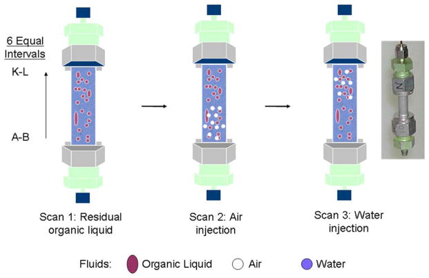
The aluminum columns were 4 cm long with an inner diameter of 0.72 cm. Prior to assembly, polypropylene porous frits (10 μm pores) were placed in the column end caps to promote uniform flow and retain the porous media. A steel distribution plate was also placed in the bottom end cap to promote uniform flow. The column axes were labeled alphabetically beginning at the bottom/influent end of the column (Figure 1) to denote the scan intervals used for the imaging described below. For the sand, column packing was done under ponded conditions using de-aired water to obtain saturated columns. For the soil, the column was packed with air-dried soil and then purged with CO2, after which de-aired water was pumped upward through the A-B end of the column to attain water saturation. The columns were flushed with de-aired water for approximately 18 hours at a flow rate of ~8 cm/hr. The bulk density and porosity of the packed sand columns were 1.67 g cm−1 and 0.37, respectively, and were 1.57 g cm−1 and 0.40, respectively, for the soil-packed column.
Figure 1.
Schematic of immiscible displacements and associated imaging for the experiments. Also shown is the scanning interval labeling for the soil-packed column.
Displacement Methods
A series of immiscible displacements was conducted for each column to generate transitions between two-phase and three-phase systems (see Figure 1). Imaging was conducted after each relevant point. An initial scan was conducted to ensure the columns were fully saturated with water. Organic liquid was then injected into the columns, followed by water imbibition, to develop a residual saturation of organic liquid. Scan 1 was conducted after this point. A small volume of air was then injected into the column to create three-phase conditions. Scan 2 was conducted after this point. Finally, water was imbibed again, and scan 3 was conducted at this point.
The organic liquid was introduced by injecting 1–2 pore volumes (~1 ml) of neat TCE into the K-L end of the vertically oriented column using a gas-tight syringe (Gastight Hamilton Company syringe, Reno, Nevada) attached to a syringe pump (Sage Model 355). Electrolyte solution saturated with TCE (in dissolved state) was injected downward through the A–B end of the column to displace TCE liquid and establish a residual saturation of organic liquid. The solution was injected at a low flow rate for two pore volumes, followed by several pore volumes at a larger flow rate. The capillary number for this displacement process was approximately 10−6, which is similar to that used in prior research to obtain a stable, discontinuous distribution of non-wetting liquid [Morrow and Chatzis, 1982]. After completion of the organic-liquid entrapment process, air was introduced into the A–B end of the column using the syringe pump. Finally, water was injected into the column in the vertical upward direction through the A–B end of the column. One set of displacements was conducted for the soil, and two sets were conducted for the sand (using two separate columns).
X-Ray Microtomography
Sequentially repeated imaging (i.e., scans 1, 2, and 3) of the same column was used to characterize fluid configuration and interfacial area before and after various fluid displacements. This allowed quantitative investigation of the impact of transitions from two-phase to three-phase systems, and from three-phase back to two-phase, with a specific focus on the morphology and interfacial area of the organic liquid. Fluid flow was terminated during each scan, which means that actual fluid displacement was not captured. However, the approach used provides data that supports the objectives of the study.
Imaging for the soil column was conducted at the GeoSoilEnviroCARS (GSECARS) 13-BM-D beamline at the Advanced Photon Source (APS), Argonne National Laboratory, IL. A summary of the specific beamline setup at the GSECARS BM-13D beamline has been reviewed elsewhere [Culligan et al., 2004; Schnaar and Brusseau, 2005]; a brief description will be presented here. Imaging was conducted by directing the monochromatic X-ray beam through the column, perpendicular to the longitudinal axis. The images were collected sequentially above and below the iodine K-edge (33.0169 and 33.269 kV) to resolve the doped organic liquid. The transmitted X-rays were converted to visible light with a single-crystal scintillator and projected onto a mirror at a 45° incline to the incoming beam. A photograph of the image on the mirror was then taken with a high-resolution CCD camera attached to a microscope objective (5×). This image represents a depth-integrated gray scale map of the linear attenuation of the X-ray beam, as it passed through the column. After an image was collected, the column was rotated 0.25° and the image acquisition process was repeated. A total of 720 two dimensional images of each sample were collected in this manner through a 180° rotation. The imaging window was approximately 5 mm vertical and spanned the entire column width. Thus, the column was scanned 6 times to complete imaging of the entire length of the packed column (see column intervals shown in Figure 1). The set of 2-D images collected for a given scan was preprocessed and reconstructed with GSECARS beamline algorithms to build a single 3-D image file from the 2-D images. The resolution for all scans was ~11 μm.
Imaging for the sand experiments was conducted at the Environmental Molecular Sciences Laboratory (EMSL) at Pacific Northwest National Laboratory using a Nikon (X-tek/Metris) XTH 320/225 kV X-ray tomography system. A voltage of 170 kV and 170 uA were used with a tungsten filament to generate X-rays for all columns, a 0.5 mm copper filter was used during image collection, shuttling mode ring artifact correction was used, and an exposure time of 0.725 seconds per frame was used. The detector collected 3143 projections for every 360 degrees of rotation, and a prescribed number of frames (4 frames/projection) were collected for each partial degree of rotation. These frames were then statistically averaged to reduce noise. Reconstruction of each projection was performed using the CT Pro software, which employs a filtered back-projection method. The entire column length was scanned at one time, with a resolution of ~22 μm.
The software package Blob3D [Kaetcham, 2005] was used for additional image processing and extraction of quantitative information, as described elsewhere [Schnaar and Brusseau, 2005; 2006a]. A global thresholding technique was used, whereby the average gray scale value of each phase was used to determine the threshold for a given image set. This was done to create an array of binary images wherein voxels considered to be organic liquid were assigned a gray scale of 255 (white), and all other phases were assigned unique gray scale values between 255 and 0 (black). Contiguous voxels assigned as the fluid of interest were identified and combined to form three-dimensional units (i.e., “blobs”). The results of prior research have demonstrated that these methods produce accurate characterization of non-wetting fluid volumes, surface areas, and interfacial areas [Schnaar and Brusseau, 2005; Brusseau et al., 2008; Narter and Brusseau, 2010], which are the focus of the present study.
Once data processing was complete, quantitative information was generated for each individual organic liquid blob. Individual blob volumes were calculated as the total volume of all the voxels contained within each blob. Surface area was calculated for each organic-liquid blob from the isosurface connecting the selected gray scale value in the binarized image. A feature of Blob3D called isosurface smoothing was implemented to account for the pixilation of smooth surfaces caused by the finite resolution of the microtomography technique and data binarization due to thresholding. Additional data processing was conducted to quantify organic-liquid volume and surface areas for all individual blobs in contact with air, and for all individual blobs not in contact with air for each of the scans conducted for all 3 experiments. This allowed direct quantitative analysis of the impact of air on blob morphology. For each of the sand experiments, additional image processing was conducted to evaluate the potential impact of wall effects.
Interfacial areas and surface-area-to-volume ratios were calculated for each individual organic-liquid blob. The latter was used as a surrogate for presentation and discussion of interfacial areas to account for the differences in fluid saturations among different intervals and displacement steps. Bulk calculations of surface-area-to-volume ratios were also determined for the column intervals and the entire column. The total surface area of the organic liquid (i.e., TCE) was used to determine the total interfacial area between TCE and both water and air. For the two-phase (TCE-water) system, this interfacial area comprises only organic-liquid/water interfaces. For the three-fluid-phase system, the total organic-liquid interfacial area consists of both organic-liquid/water and air/organic-liquid interfaces. The total specific organic-liquid interfacial area (ANW, cm−1) was determined by dividing the total measured organic-liquid interfacial area by the volume of the porous medium comprising the imaged domain.
RESULTS AND DISCUSSION
Fluid Distributions and Configurations
Inspection of the image data revealed that the organic liquid, water, air, and the porous-medium grains were well distinguished by both XMT methods, similar to prior XMT imaging for three fluids [Feali et al., 2012; Schnaar and Brusseau, 2006a]. The resolution was sufficient to delineate the continuity of each of the fluid phases, including distinguishing individual phase bodies. The organic-liquid blobs were distributed nonuniformly throughout the domain as would be expected for a natural porous medium. However, the blobs were observed to be generally distributed evenly throughout the scanned intervals, both longitudinally and radially. Organic-liquid blobs in the center and outer sections of the columns appeared to have similar morphologies. These results suggest that wall effects were minimal, which is consistent with prior XMT imaging of organic liquid within the same sand and soil used for this research [Brusseau et al., 2008; Russo et al., 2009]. The issue of potential wall effects will be further considered below. The organic-liquid blob morphologies for the organic-liquid-water (two-phase) systems were consistent with those reported in prior imaging studies of two-phase systems [Al-Raoush and Willson, 2005; Schnaar and Brusseau, 2005; 2006a; Zhang et al., 2002]. Organic-liquid blobs varied greatly in both size and shape, ranging from small spheres (≥ 0.03-mm in diameter) to large, amorphous ganglia with lengths of 4–5 mm.
For the soil-packed column, air injection resulted in its distribution primarily within intervals A–B and C–D, with a small fraction in interval E–F. Essentially no air was present in intervals G–H through K–L. The air existed as both discontinuous singlets and continuous multipore ganglia. The air singlets varied significantly in size and shape, and were generally smaller and more spherical than the organic-liquid blobs, as would be expected based on relative organic-liquid/water and air/water interfacial tensions.
A significant portion of the organic liquid existed as lenses and films in contact with air for the section of the column under three-phase conditions. These lenses and films were not observed in the section of the column under two-phase (organic-liquid/water) conditions, nor were they observed prior to air injection. Similar results were observed for the sand-packed columns upon injection of air. These results are consistent with those reported by Schnaar and Brusseau [Schnaar and Brusseau, 2006a].
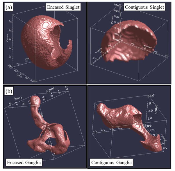
Representative three-dimensional renderings of individual organic-liquid blobs obtained from the three-phase section of the soil-packed column are presented in Figure 2. The uppermost blobs (Figure 2a) are examples of single-pore blobs (singlets), and the lower-most blobs (Figure 2b) are examples of multipore blobs (ganglia). The nonwetting fluid (air) was either encased within (left-most images) or contiguous to (right-most images) the intermediate-wetting fluid (organic liquid). These images illustrate the significant impact of air on organic-liquid morphology. For three-phase systems, air (i.e., as the nonwetting phase) encased in organic liquid is analogous to organic liquid in two-phase organic-liquid/water systems (i.e., as the nonwetting phase) as described in Lenhard et al. (2004), who note that organic liquid at residual saturation can be either occluded (fully encased) or partially occluded by water. With the addition of air, the organic liquid switched from being the nonwetting phase to the intermediate-wetting phase, which resulted in the alteration of morphology from more spherical structures to more planar structures. Although contact angle is generally defined with respect to the solid surface being wetted, it does appear that the organic-liquid contact angle is increased significantly as the intermediate wetting fluid (i.e., wetting the air phase) relative to the nonwetting condition (i.e., wetting solid surfaces). However, recent research suggests that contact angles may vary over a range of values related to variability and heterogeneity in wetting conditions and pore-scale multifluid configurations [e.g., Andrew et al., 2014b].
Figure 2.
Three-dimensional renderings of organic-liquid blobs isolated from the imaged domain within the soil-packed column. The upper-most blobs (a) are examples of single pore blobs (singlets), and the lower-most blobs (b) are examples of multipore blobs (ganglia). The relationship between the organic liquid and the air filled voids illustrate that nonwetting fluid (air) can either be encased (left-most images) or contiguous to (right-most images) the intermediate wetting fluid (organic liquid).
Upon water imbibition into the soil-packed column, most, but not all, of the air was displaced from sections A–B and C–D. The displaced air was distributed primarily into section E–F, with small amounts in the downgradient portion of the column. Water imbibition into the sand-packed columns resulted in displacement of air from the columns, with some air remaining. For the intervals wherein air was not completely displaced after water imbibition, the configuration of the air was considerably more discontinuous, existing primarily as singlets. The fraction of organic liquid in contact with air changed in correspondence to the change in air volume present (Tables 1–3). The vast majority of organic-liquid blobs and porous-media grains remained in the same vertical location in the succeeding scan, indicating minimal mobilization.
Table 1.
Aggregate, column-wide characteristics of organic liquid blobs for soil experiment.
| fN Air contact | fN No-Air contact | SN Total | Median Volume Air Contact | Median Volume No-Air Contact | SA/VOL Air contact | SA/VOL No-Air contact | SA/VOL Total | |
|---|---|---|---|---|---|---|---|---|
| (mm3) | (mm3) | (mm−1) | (mm−1) | (mm−1) | ||||
| Scan 2 | 0.23 | 0.77 | 14 | 0.028 | 0.012 | 13.2 | 14.7 | 13.3 |
| Scan 3 | 0.15 | 0.85 | 8 | 0.046 | 0.009 | 12.1 | 10.7 | 11.8 |
SA = surface area of organic liquid, V = volume of organic liquid, fN is the fraction of organic liquid in contact or not in contact with air, and SN = residual saturation of organic liquid
Table 3.
Aggregate, column-wide characteristics of organic liquid blobs for sand experiment 2.
| fN Air contact | fN No-Air contact | SN Total | Median Volume Air Contact | Median Volume No-Air Contact | SA/VOL Air contact | SA/VOL No-Air contact | SA/VOL Total | |
|---|---|---|---|---|---|---|---|---|
| (mm3) | (mm3) | (mm−1) | (mm−1) | (mm−1) | ||||
| Scan 1 | 0 | 1 | 21 | - | 0.011 | - | 21.3 | 21.3 |
| Scan 2 | 0.55 | 0.45 | 15 | 0.166 | 0.007 | 27.7 | 27.2 | 27.5 |
| Scan 3 | 0.21 | 0.79 | 10 | 0.062 | 0.006 | 25.6 | 27.3 | 26.9 |
SA = surface area of organic liquid, V = volume of organic liquid, fN is the fraction of organic liquid in contact or not in contact with air, and SN = residual saturation of organic liquid
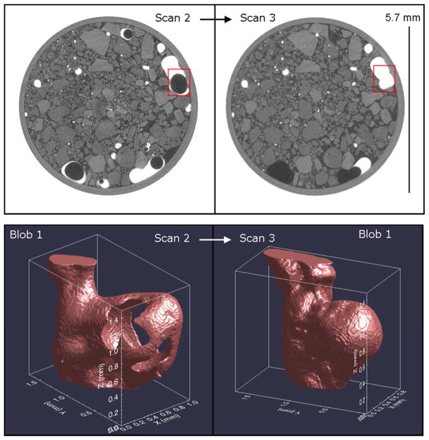
Two-dimensional image sections of the soil-packed column collected from the same location within interval C–D before and after water imbibition are presented in Figure 3a. Organic-liquid blobs outlined within the image sections are shown in Figure 3b as three-dimensional renderings. These images are of the same organic-liquid blob (blob 1) collected from Scans 2 and 3 on the left and right, respectively. The void shown within the organic-liquid blob from Scan 2 is not present in the blob from Scan 3, which indicates that air was displaced from the blob during imbibition. These figures illustrate the significant change in morphology the blobs underwent from scan 2 to 3 upon air displacement, and indicate the reversibility of the changes in blob morphology that occurred when the system changed from the original two-phase system to a three-phase system upon addition of air. Thus, the dynamic, malleable nature of organic-liquid morphology under immiscible-displacement conditions is demonstrated.
Figure 3.
(a) Cross-section image sections from the soil-packed column collected from the same location in the column before (Scan 2) and after (Scan 3) water imbibition. Organic liquid is white, porous-media grains are light gray, the aqueous-phase is dark gray, and the gas is black. (b) Three-dimensional renderings of the organic-liquid blob highlighted by a square in part (a) illustrating the impact of immiscible displacement of the encased air phase on the organic-liquid morphology and surface area. The ganglia was cropped above and below the area of interest to isolate the volume impacted by the air phase, and the image was oriented such that its Z axis is parallel to the column’s longest dimension and the direction of flow, which was upwards.
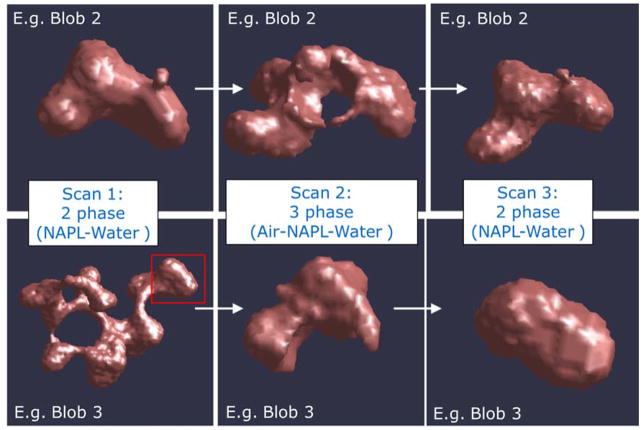
A similar illustration of changes in blob morphology is presented for the sand experiments in Figure 4. This figure shows the 3D rendering of two organic-liquid ganglia as measured in Scan 1, Scan 2, and Scan 3 for experiment 1. For the upper series (blob 2) of the figure, the organic liquid is deformed as an air bubble displaced into the center of the organic liquid, and organic liquid spreading (i.e., wetting) over the gas phase is observed. A small protruding ganglion on the right side of the organic liquid in Scan 1 disappears during Scan 2, and then the small protruding ganglion on the right side is reformed when the air is displaced in Scan 3. Within the lower series (blob 3), the right side of the ganglia highlighted in the box for the image from Scan 1 is the focus of inspection for the images from Scans 2 and 3. This contiguous ganglion becomes separated from the remainder of the organic liquid for Scan 2 due to the organic liquid deformation by an air bubble. Scan 3 shows the increased sphericity and reduction in surface area (compared to Scan 2) upon removal of the air bubble. However, the ganglion was snapped off from the remainder of the organic liquid. Recently, researchers have indicated that pore-scale heterogeneity (i.e., pore and throat size variability) can create fluid configuration variability, which impacts flow and fluid retention processes including snap-off and droplet fragmentation [Andrew et al., 2014a; Pak et al., 2015]. These results suggest that transitions of the organic liquid to the intermediate wetting phase and back to the nonwetting phase may have both reversible and irreversible impacts on the configuration and morphology of the fluids at the pore scale.
Figure 4.
Three-dimensional renderings of the same organic-liquid blobs imaged for the two- phase (Scan 1), three-phase (Scan 2), and two-phase (Scan 3) systems for the sand-packed column. For the lower series (e.g. blob 3), the ganglia within the highlighted box is the focus for subsequent images from Scans 2 and 3.
Characterization of Fluid Surface Areas and Fluid-Fluid Interfacial Areas
The median volumes of the organic-liquid blobs are reported in Tables 1, 2, and 3 for the soil and sand experiments, respectively. The median volumes are significantly larger for the organic-liquid blobs in contact with air for both media. It is hypothesized that this reflects the distribution of air, wherein it is expected that air as the non-wetting fluid would be associated with the largest-diameter pore sequences upon displacement (drainage). It has been shown that the diameter of organic-liquid blobs correlates to pore/grain size (e.g., Brusseau et al., 2009).
Table 2.
Aggregate, column-wide characteristics of organic liquid blobs for sand experiment 1.
| fN Air contact | fN No-Air contact | SN Total | Median Volume Air Contact | Median Volume No-Air Contact | SA/VOL Air contact | SA/VOL No-Air contact | SA/VOL Total | |
|---|---|---|---|---|---|---|---|---|
| (mm3) | (mm3) | (mm−1) | (mm−1) | (mm−1) | ||||
| Scan 1 | 0 | 1 | 13 | - | 0.006 | - | 25.3 | 25.3 |
| Scan 2 | 0.59 | 0.41 | 6.8 | 0.008 | 0.004 | 30.4 | 27.5 | 29.2 |
| Scan 3 | 0.02 | 0.98 | 6 | 0.137 | 0.005 | 24.7 | 27.0 | 27.0 |
SA = surface area of organic liquid, V = volume of organic liquid, fN is the fraction of organic liquid in contact or not in contact with air, and SN = residual saturation of organic liquid
Surface areas were calculated for each organic-liquid blob and normalized by the associated individual blob volume to determine the surface-area-to-volume ratio (i.e., SA/V) for each blob. Additionally, the aggregate SA/V ratios for each entire column are reported in Tables 1, 2, and 3. The aggregate organic-liquid SA/V values increased from scan 1 (two-phase) to scan 2 (three-phase). Conversely, the aggregate organic-liquid SA/V values decreased from Scan 2 to Scan 3. The reductions in SA/V likely reflect the displacement of air from the interval, and the concomitant change in organic-liquid morphology to that of a two-phase system from a three-phase system (i.e., smaller SA/V for a given blob size), as illustrated in Figures 3 and 4.
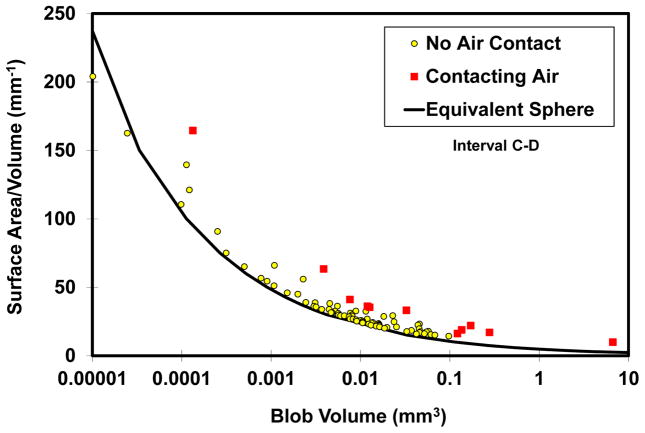
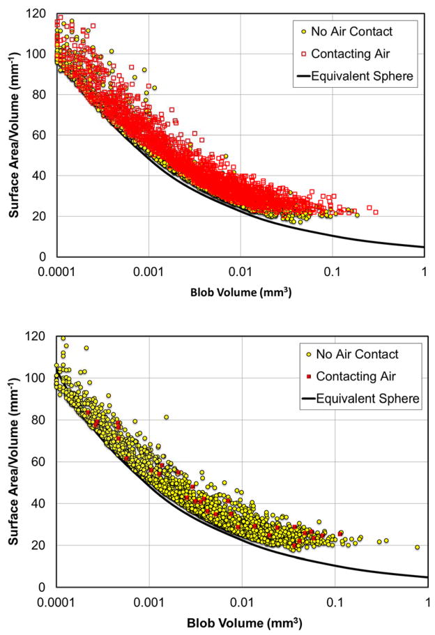
The SA/V values for individual organic-liquid blobs are plotted as a function of individual blob volume for the soil experiment in Figure 5 for interval C–D. The solid line represents the SA/V relationship for a perfect sphere of equivalent volume, which is presented for comparative evaluation of deviations from sphericity. Figure 6 presents the SA/V values for all individual organic-liquid blobs plotted as a function of individual blob volume for sand experiment 1. The upper figure represents the transition to a three-phase system upon air injection (scan 2), and the lower figure represents the transition back to a two-phase system upon injection of water and displacement or dissolution of air (scan 3). Similar results were obtained for sand experiment 2. For both media, the organic-liquid blobs that were in contact with the air exhibit, on-aggregate, greater deviations from the line, indicating lower sphericity. This is consistent with the observation that some of the organic liquid existed as lenses and films in the three-phase system. These results are consistent with two-phase versus three-phase observations reported in Schnaar and Brusseau [Schnaar and Brusseau, 2006a].
Figure 5.
Volume-normalized surface area of organic liquid blobs versus organic-liquid blob volume for all organic-liquid blobs that were in contact with the air phase (Contacting Air) and for all organic-liquid blobs that were not in contact with the air phase (No air Contact) for the soil-packed column. Data are reported for after air injection (Scan 2) and after water imbibition (Scan 3) for interval C–D. Each data point represents an individual organic-liquid blob. The solid line represents the surface-area-to-volume ratio for a perfect sphere of equivalent volume.
Figure 6.
Volume-normalized surface area of individual organic-liquid blobs versus organic-liquid blob volume for all organic-liquid blobs that were in contact with the air phase (Contacting Air) and for all organic-liquid blobs that were not in contact with the air phase (No air Contact) for the sand-packed column (exp 1). Data are reported for after air injection (Scan 2, Top), and after water imbibition (Scan 3, bottom) for the entire column. Each data point represents an individual organic-liquid blob. The solid line represents the surface-area-to-volume ratio for a perfect sphere of equivalent volume.
Morphological information was tabulated separately for organic-liquid blobs in contact with the wall and those not in contact with the wall to evaluate the potential impact of wall effects for the sand experiments. The measured aggregate SA/V values for the entire columns and intervals of the columns were plotted for the two data sets (data not shown). The results showed that there is negligible difference between the two sets of data, with a slope of 1.0 and R2 = 0.99 for the comparison plot. This finding indicates that the morphology of the blobs located adjacent to the wall is similar to the morphology of blobs not in contact with the wall, and thus that wall effects were minimal.
One simple way by which to characterize the morphology of 3D objects is to determine their fractal dimensions [e.g., Fontenot and Vigil, 2002]. Objects with a fractal dimension of 2/3 are considered Euclidean objects, which are perfectly space filling and spherical. A fractal analysis was conducted to characterize the morphology of the organic-liquid blobs for the data sets reported herein. The slope of a log-log plot of blob surface area versus blob volume represents the ratio of area and volume fractal dimensions (data not shown). The aggregate fractal dimensions for all blobs not in contact with air were 0.69 for the soil, 0.74 for sand expt 1, and 0.73 for sand expt 2. For blobs that were in contact with air, the values were 0.72. 0.77, and 0.76 for soil, sand-1, and sand-2, respectively. It is observed that the fractal dimension is larger for blobs in contact with air for all three cases, indicating that the blobs are less spherical. This is consistent with the analyses presented above.
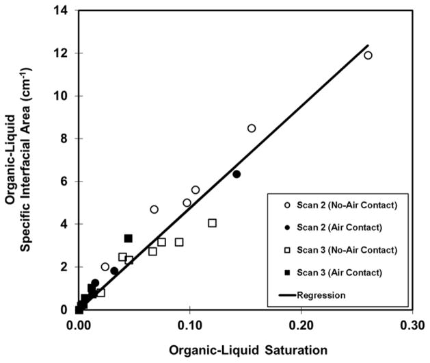
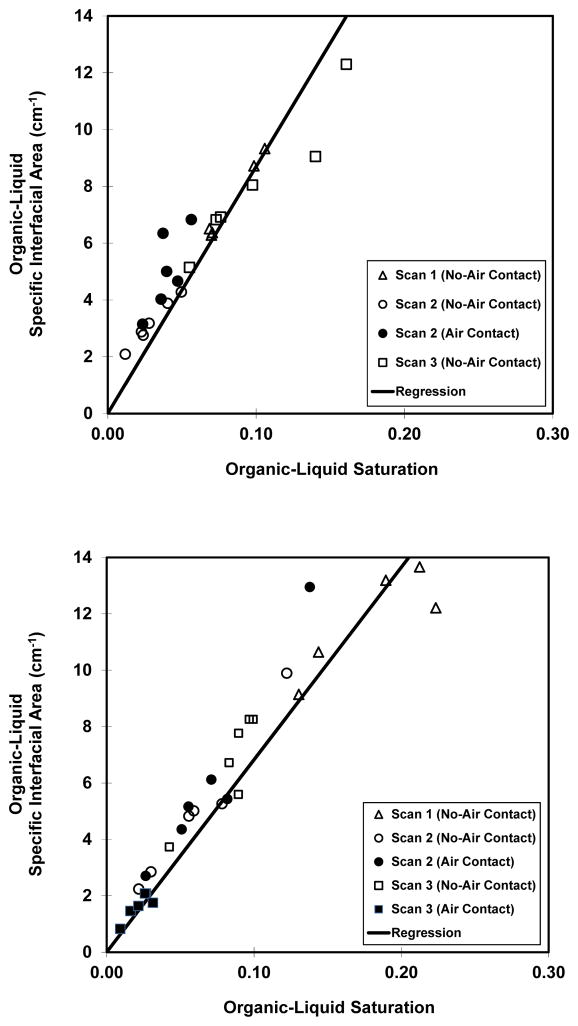
The specific organic-liquid interfacial areas (i.e., ANW) are presented in Figures 7 and 8 as a function of imaged or synthetic interval for the soil and sand, respectively. The data are reported with separate tabulations for the organic liquid in contact with air and the organic liquid not in contact with air to allow direct comparison. It is important to note that the specific interfacial areas associated with these two tabulations are different. For organic-liquid blobs not in contact with air, the organic-liquid interfacial area comprises solely organic-liquid/water interface. Conversely, for organic-liquid blobs that are in contact with air, the organic-liquid interfacial area comprises both organic-liquid/water interface and air/organic-liquid interface. The ANW values increase linearly with increasing organic-liquid saturation, consistent with prior reports. The similarity of ANW values between the two- and three-phase systems indicates that total organic-liquid interfacial area is consistent between two- and three-phase systems. This result may at first consideration appear to be in contrast to the SA/V results discussed above. However, first, the changes in SA/V noted above are relatively small on aggregate (~10–30%). Second, noting that ANW = SA/V * θN (where θN is organic-liquid content), it is observed that ANW is influenced by changes in both SA/V and θN. Given that θN also changed between displacements, there is not a direct simple relationship between changes in SA/V and the extant ANW- SN function. Third, it is recognized that the tabulated ANW values for the blobs in contact with air include both organic-liquid/water and air/organic-liquid interface, as noted above. The magnitude of solely organic-liquid/water interfacial area will of course decrease for the three-phase system. Inspection of Figures 7 and 8 also shows that the ANW values for blobs not in contact with air are consistent from scan 1 to scan 2 to scan 3, i.e., they are consistent over the transitions from two-phase to three-phase and back to two-phase conditions. This suggests that interfacial area is conserved over transitions between two- and three-phase conditions.
Figure 7.
Aggregate specific total organic-liquid interfacial area (ANW) versus organic-liquid saturation (SN) for all organic-liquid blobs that were in contact with air (Air Contact), and for all organic-liquid blobs that were not in contact with air (No air Contact) for the soil-packed column. Data are presented as a function of imaged interval, for after air injection (Scan 2) and after water imbibition (Scan 3). Note that the ANW values for “Air Contact” comprise both organic-liquid/water and air/organic-liquid interfaces.
Figure 8.
Specific total organic-liquid interfacial area (ANW) versus organic-liquid saturation (SN) for all organic-liquid blobs that were in contact with air (Air Contact), and for all organic-liquid blobs that were not in contact with air (No air Contact) for the sand-packed column (exp 1 = Upper, exp 2 = Lower). Data are presented as a function of synthetic interval, wherein the full-column data were split into 5 intervals for evaluation of spatial distribution effects. The data are tabulated for before air injection (scan 1), after air injection (Scan 2), and after water imbibition (Scan 3). Note that the ANW values for “Air Contact” comprise both organic-liquid/water and air/organic-liquid interfaces.
SUMMARY
The behavior of immiscible liquids transitioning between two and three-phase systems with respect to pore-scale configuration and morphology was investigated using XMT for both soil and sand media. For the three-phase system, a significant portion of the organic liquid was observed to exist as lenses and films in contact with the air (nonwetting) phase, which was distributed both as encased within (occluded) or contiguous to the organic-liquid (intermediate wetting) phase. Upon water imbibition, the air was displaced downgradient and concomitantly the morphology of the organic–liquid blobs reverted to that characteristic of two-phase systems as the lenses and films were replaced by more spherical features. These results illustrate the malleable nature of fluid configuration under multiphase flow conditions, and indicate that the occurrence, spatial distribution, and mobility of air within three-phase systems alters the configuration and morphology of the organic liquid.
SA/V values for organic-liquid blobs were larger for organic liquid in contact with air (three-phase) compared to organic liquid not in contact with air (two-phase), reflecting the differences in morphology. The differences in aggregate (column-wide) SA/V values were relatively moderate (~10–30%), reflecting the fact that not all blobs were impacted by the presence of air and that some that were had minimal changes in morphology. However, much greater differences were observed for some individual blobs. The significant changes observed in configuration and interfacial area for these blobs could have significant impacts on localized pore-scale mass-transfer and fluid-flow phenomena. The results have implications for conceptual and numerical modeling and upscaling of multiphase fluid flow and mass transfer.
Acknowledgments
This work was supported by the NIEHS Superfund Basic Research Program (P42 ESO4940). The GeoSoilEnviroCARS (Sector 13) facility at the Advanced Photon Source (APS), Argonne National Laboratory, is supported by the National Science Foundation - Earth Sciences (EAR-0217473), Department of Energy (DOE) - Geosciences (DE-FG02-94ER14466) and the State of Illinois. A portion of the research was also performed using EMSL, a DOE Office of Science User Facility sponsored by the Office of Biological and Environmental Research and located at Pacific Northwest National Laboratory (Proposal # 44728). We would like to thank Mathew Narter (University of Arizona), Dr. Tomas Varga (EMSL), Dr. Rivers (APS), and Dr. Ketcham (University of Texas at Austin). Raw data used in this work are available free of charge upon request. We thank the reviewers for their constructive, helpful comments.
LITERATURE CITED
- Al-Raoush RI. Impact of wettability on pore-scale characteristics of residual nonaqueous phase liquids. Environ Sci Technol. 2009;43:4796–4801. doi: 10.1021/es802566s. [DOI] [PubMed] [Google Scholar]
- Al-Raoush RI, Willson CS. A pore-scale investigation of a multiphase porous media system. Journal of Contaminant Hydrology. 2005;77:67–89. doi: 10.1016/j.jconhyd.2004.12.001. [DOI] [PubMed] [Google Scholar]
- Alvarado FE, Grader AS, Karacan O, Halleck PM. Visualization of three phases in porous media using micro computed tomography. Petrophysics. 2003;48:490–498. [Google Scholar]
- Andrew M, Bijeljic B, Blunt MJ. Pore-by-pore capillary pressure measurements using X-ray microtomography at reservoir conditions: Curvature, snap-off, and remobilization of residual CO2. Water Resources Research. 2014a;50(11):8760–8774. [Google Scholar]
- Andrew M, Bijeljic B, Blunt MJ. Pore-scale contact angle measurements at reservoir conditions using X-ray microtomography. Advances in Water Resources. 2014b;68:24–31. [Google Scholar]
- Berg S, et al. Real-time 3D imaging of Haines jumps in porous media flow. P Natl Acad Sci USA. 2013;110(10):3755–3759. doi: 10.1073/pnas.1221373110. [DOI] [PMC free article] [PubMed] [Google Scholar]
- Blunt MJ, Bijeljic B, Dong H, Gharbi O, Iglauer S, Mostaghimi P, Paluszny A, Pentland C. Pore-scale imaging and modelling. Advances in Water Resources. 2013;51:197–216. [Google Scholar]
- Brown K, Schluter S, Sheppard A, Wildenschild D. On the challenges of measuring interfacial characteristics of three-phase fluid flow with x-ray microtomography. J Microsc-Oxford. 2014;253(3):171–182. doi: 10.1111/jmi.12106. [DOI] [PubMed] [Google Scholar]
- Brusseau ML, Peng S, Schnaar G, Costanza-Robinson MS. Relationships among air-water interfacial area, capillary pressure, and water saturation for a sandy porous medium. Water Resources Research. 2006;42(3) [Google Scholar]
- Brusseau ML, Peng S, Schnaar G, Murao A. Measuring air-water interfacial areas with X-ray microtomography and interfacial partitioning tracer tests. Environmental Science & Technology. 2007;41(6):1956–1961. doi: 10.1021/es061474m. [DOI] [PubMed] [Google Scholar]
- Brusseau ML, Janousek H, Murao A, Schnaar G. Synchrotron X-ray microtomography and interfacial partitioning tracer test measurements of NAPL-water interfacial areas. Water Resources Research. 2008;44(1) doi: 10.1029/2006WR005517. [DOI] [PMC free article] [PubMed] [Google Scholar]
- Brusseau ML, Narter M, Schnaar S, Marble J. Measurement and estimation of organic-liquid/water interfacial areas for several natural porous media. Environmental Science & Technology. 2009;43(10):3619–3625. doi: 10.1021/es8020827. [DOI] [PMC free article] [PubMed] [Google Scholar]
- Carroll KC, Taylor R, Gray E, Brusseau ML. The impact of composition on the physical properties and evaporative mass transfer of a PCE-diesel immiscible liquid. Journal of Hazardous Materials. 2009;164(2–3):1074–1081. doi: 10.1016/j.jhazmat.2008.09.003. [DOI] [PMC free article] [PubMed] [Google Scholar]
- Chu YJ, Werth CJ, Valocchi AJ, Yoon H, Webb AG. Magnetic resonance imaging of nonaqueous phase liquid during soil vapor extraction in heterogeneous porous media. Journal of Contaminant Hydrology. 2004;73(1–4):15–37. doi: 10.1016/j.jconhyd.2003.12.003. [DOI] [PubMed] [Google Scholar]
- Cnudde V, Boone MN. High-resolution X-ray computed tomography in geosciences: A review of the current technology and applications. Earth-Sci Rev. 2013;123:1–17. [Google Scholar]
- Cohen RM, Mercer JW. DNAPL site evaluation. C.K. Smoley; Boca Raton, FL, United States: 1993. p. 314. [Google Scholar]
- Culligan KA, Wildenschild D, Christensen BSB, Gray WG, Rivers ML, Tompson AFB. Interfacial area measurements for unsaturated flow through a porous medium. Water Resources Research. 2004;40(12) [Google Scholar]
- DiCarlo DA, Bauters TWJ, Steenhuis TS, Parlange JY, Bierck BR. High-speed measurements of three-phase flow using synchrotron X rays. Water Resources Research. 1997;33(4):569–576. [Google Scholar]
- Feali M, Pinczewski WV, Cinar Y, Arns CH, Arns JY, Turner M, Senden T, Francois N, Knackstedt M. Qualitative and quantitative analyses of the three-phase distribution of oil, water, and gas in bentheimer sandstone by use of micro-CT imaging. SPE Reservoir Evaluation & Engineering. 2012;15(6):706–711. [Google Scholar]
- Fontenot MM, Vigil RD. Pore-scale study of nonaqueous phase liquid dissolution in porous media using laser-induced fluorescence. Journal of Colloid and Interface Science. 2002;247(2):481–489. doi: 10.1006/jcis.2001.8158. [DOI] [PubMed] [Google Scholar]
- Ghosh J, Tick GR. A pore scale investigation of crude oil distribution and removal from homogeneous porous media during surfactant-induced remediation. Journal of Contaminant Hydrology. 2013;155:20–30. doi: 10.1016/j.jconhyd.2013.09.003. [DOI] [PubMed] [Google Scholar]
- Hayden NJ, Voice TC. Microscopic observation of a NAPL in a 3-fluid-phase soil system. Journal of Contaminant Hydrology. 1993;12(3):217–226. [Google Scholar]
- Iglauer S, Paluszny A, Blunt MJ. Simultaneous oil recovery and residual gas storage: A pore-level analysis using in situ X-ray micro-tomography. Fuel. 2013;103:905–914. [Google Scholar]
- Johns ML, Gladden LF. Magnetic resonance imaging study of the dissolution kinetics of octanol in porous media. Journal of Colloid and Interface Science. 1999;210(2):261–270. doi: 10.1006/jcis.1998.5950. [DOI] [PubMed] [Google Scholar]
- Ketcham RA. Computational methods for quantitative analysis of three-dimensional features in geological specimens. Geosphere. 2005;1:32–41. [Google Scholar]
- Kechavarzi C, Soga K, Wiart P. Multispectral image analysis method to determine dynamic fluid saturation distribution in two-dimensional three-fluid phase flow laboratory experiments. Journal of Contaminant Hydrology. 2000;46(3–4):265–293. [Google Scholar]
- Keller AA, Blunt MJ, Roberts PV. Micromodel observation of the role of oil layers in three-phase flow. Transport in Porous Media. 1997;26(3):277–297. [Google Scholar]
- McColl CM, Johnson GR, Brusseau ML. Evaporative mass transfer behavior of a complex immiscible liquid. Chemosphere. 2008;73(4):607–613. doi: 10.1016/j.chemosphere.2008.05.051. [DOI] [PMC free article] [PubMed] [Google Scholar]
- Morrow NR, Chatzis I. Measurement and correlation of conditions for entrapment and mobilization of residual oil. USDOE Report 10310–20 1982 [Google Scholar]
- Mumford KG, Smith JE, Dickson SE. Mass flux from a non-aqueous phase liquid pool considering spontaneous expansion of a discontinuous gas phase. Journal of Contaminant Hydrology. 2008;98(3–4):85–96. doi: 10.1016/j.jconhyd.2008.02.007. [DOI] [PubMed] [Google Scholar]
- Mumford KG, Dickson SE, Smith JE. Slow gas expansion in saturated natural porous media by gas injection and partitioning with non-aqueous phase liquids. Advances in Water Resources. 2009;32(1):29–40. [Google Scholar]
- Narter M, Brusseau ML. Comparison of interfacial partitioning tracer test and high-resolution microtomography measurements of fluid–fluid interfacial areas for an ideal porous medium. Water Resour Res. 2010;46:W08602. doi: 10.1029/2009WR008375. [DOI] [PMC free article] [PubMed] [Google Scholar]
- Oostrom M, Dane JH, Wietsma TW. Removal of carbon tetrachloride from a layered porous medium by means of soil vapor extraction enhanced by desiccation and water table reduction. Vadose Zone Journal. 2005;4(4):1170–1182. [Google Scholar]
- Pak T, I, Butler B, Geiger S, van Dijke MIJ, Sorbie KS. Droplet fragmentation: 3D imaging of a previously unidentified pore-scale process during multiphase flow in porous media. P Natl Acad Sci USA. 2015;112(7):1947–1952. doi: 10.1073/pnas.1420202112. [DOI] [PMC free article] [PubMed] [Google Scholar]
- Prodanovic M, Lindquist WB, Seright RS. Porous structure and fluid partitioning in polyethylene cores from 3D X-ray microtomographic imaging. Journal of Colloid and Interface Science. 2006;298(1):282–297. doi: 10.1016/j.jcis.2005.11.053. [DOI] [PubMed] [Google Scholar]
- Roy JW, Smith JE. Multiphase flow and transport caused by spontaneous gas phase growth in the presence of dense non-aqueous phase liquid. Journal of Contaminant Hydrology. 2007;89(3–4):251–269. doi: 10.1016/j.jconhyd.2006.09.011. [DOI] [PubMed] [Google Scholar]
- Russo AE, Narter M, Brusseau ML. Characterizing pore-scale dissolution of organic immiscible liquid in a poorly-sorted natural porous medium. Environmental Science \& Technology. 2009;43(15):5671–5678. doi: 10.1021/es803158x. [DOI] [PMC free article] [PubMed] [Google Scholar]
- Schluter S, Sheppard A, Brown K, Wildenschild D. Image processing of multiphase images obtained via X-ray microtomography: A review. Water Resources Research. 2014;50(4):3615–3639. [Google Scholar]
- Schnaar G, Brusseau ML. Pore-scale characterization of organic immiscible-liquid morphology in natural porous media using synchrotron X-ray microtomography. Environmental Science & Technology. 2005;39(21):8403–8410. doi: 10.1021/es0508370. [DOI] [PubMed] [Google Scholar]
- Schnaar G, Brusseau ML. Characterizing pore-scale configuration of organic immiscible liquid in multiphase systems with synchrotron X-ray microtomography. Vadose Zone Journal. 2006a;5(2):641–648. [Google Scholar]
- Schnaar G, Brusseau ML. Characterizing pore-scale dissolution of organic immiscible liquid in natural porous media using synchrotron X-ray microtomography. Environmental Science & Technology. 2006b;40(21):6622–6629. doi: 10.1021/es0602851. [DOI] [PubMed] [Google Scholar]
- Schroth MH, Istok JD, Selker JS. Three-phase immiscible fluid movement in the vicinity of textural interfaces. Journal of Contaminant Hydrology. 1998;32(1–2):1–23. [Google Scholar]
- Vangeel PJ, Sykes JF. Laboratory and model simulations of a LNAPL spill in a variably-saturated sand .1. laboratory experiment and image- analysis techniques. Journal of Contaminant Hydrology. 1994;17(1):1–25. [Google Scholar]
- Waduge WAP, Soga K, Kawabata J. Physical modeling of LNAPL source zone remediation by air sparging. Vadose Zone Journal. 2007;6(2):413–422. [Google Scholar]
- Werth CJ, Zhang C, Brusseau ML, Oostrom M, Baumann T. A review of non-invasive imaging methods and applications in contaminant hydrogeology research. Journal of contaminant hydrology. 2010;113(1–4):1–24. doi: 10.1016/j.jconhyd.2010.01.001. [DOI] [PMC free article] [PubMed] [Google Scholar]
- Wilkins MD, Abriola LM, Pennell KD. An experimental investigation of rate-limited nonaqueous phase liquid volatilization in unsaturated porous-media - steady-state mass-transfer. Water Resources Research. 1995;31(9):2159–2172. [Google Scholar]
- Zhang CY, Werth CJ, Webb AG. A magnetic resonance imaging study of dense nonaqueous phase liquid dissolution from angular porous media. Environmental Science & Technology. 2002;36(15):3310–3317. doi: 10.1021/es011497v. [DOI] [PubMed] [Google Scholar]


