Abstract
Background: Extension block splinting of the proximal interphalangeal (PIP) joint is a simple and useful treatment option although the practical application of this technique has remained undefined in the literature. Methods: This article provides a step-by-step technique for the construction of a reliable PIP extension block splint and also reviews basic indications for treatment with a PIP extension block splint as well as other PIP extension block splint designs. Results: The proposed splint design outlined in this article is reliable, easy to reproduce and easy for patients to manage when treated with a PIP extension block splint. Conclusions: PIP extension block splinting has a role for certain injuries and certain post-operative protocols. A reliable splint design that is easy to manage makes this treatment choice more attractive to the surgeon and the patient.
Keywords: dorsal block, extension block, splint, thermoplast splint, finger splint, PIP
Introduction
Extension block splinting of the proximal interphalangeal (PIP) joint is useful for the treatment of some PIP joint fractures and dislocations or as part of post-operative rehabilitation, such as protection of the PIP joint volar plate repair. The concept of the extension block splint is relatively simple. The splint blocks a specific arc of terminal PIP joint extension while allowing unrestricted flexion. The splint is typically worn on a full-time basis over the span of many weeks.
Although the concept seems simple, we found the fabrication of splint designs suggested in the literature difficult to achieve, and comfort and reliability suboptimal. This article reviews our experience with suggested designs in the literature and describes our design for a PIP joint extension block splint that is easy to produce, is adjustable, truly blocks extension, is comfortable to wear, and is easy for patients to manage.
Anatomy
The PIP joint is a bicondylar joint with a high degree of intrinsic stability provided by the congruency of the opposing joint surfaces of the middle phalangeal base and proximal phalangeal head. The dome-shaped base of the middle phalanx matches the round proximal phalangeal head on the lateral radiographic view of the PIP joint. Compromise of the buttressing effect of the volar lip of the middle phalangeal base can result in dorsal instability of the PIP with the degree of instability directly related to the degree of bone loss.1 The volar plate of the PIP joint is also an important volar-sided stabilizing structure and its compromise can result in PIP joint hyperextension.
Indications and Contraindications
PIP fracture-subluxations occur when fractures of the middle phalangeal base compromise the buttressing effect of its volar lip resulting in dorsal instability and subluxation of the remaining uninjured middle phalangeal base joint surface relative to the proximal phalangeal head. This injury pattern is a relatively common indication for an extension block splint when the uninjured portion of the joint reduces in PIP joint flexion. PIP joint fracture-subluxations that do not reduce in flexion or require extreme flexion would be contraindicated for the use of this splinting technique alone and may likely require operative intervention. In addition, the use of this splint could be indicated as part of a post-operative splinting protocol when the surgeon desires maintenance of early motion while avoiding the extremes of PIP extension such as after PIP volar plate arthroplasty and after hemi-hamate PIP reconstruction.
Splint Designs
There are various forms suggested in the medical literature for the design of a PIP joint extension block splint. One early design suggested a forearm-based cast that extends over the involved finger to block extension.2 Although we have not used this cast in practice, this design seemed to have obvious disadvantages. This design is large and cumbersome for the treatment of a single PIP joint. The use of cast material is heavy and a forearm-based device necessitates immobilization of the wrist. Also, a permanent cast is not removable for skin inspection.
Conversely, some authors suggest a small and minimalist design applied only to the injured digit.5 This splint is constructed from aluminum-backed foam and centered over the dorsal PIP joint. It is bent to the desired angle and secured with tape to the proximal phalanx only. This design has the advantages of simplicity, low cost, and the involvement of the least amount of joints; however, the reality of this design can be quite disappointing. First, many patients do not tolerate the circumferential taping of a swollen finger fresh after injury. Second, as the splint is anchored around the proximal phalanx alone, it tends to spin around the long axis of the finger and lose its essential dorsal position. Third, the foam for commercially available splints is frequently too thick such that the extension blocking ability of the splint is not reliable and is subject to the “give” of the foam. Thus, some designs have peeled off the foam backing for just this reason.5
McPhee has also suggested a simple splint using a figure 8–type design.3 A modified figure 8 thermoplast cutout is contoured to fit with the proximal and distal limbs of figure 8 over the dorsal proximal and dorsal middle phalanx, respectively, whereas the mid-portion of figure 8 lies over the volar PIP flexion crease. This design is simple, but difficult to fit on an acutely injured swollen digit and can lose its position if it swivels around the longitudinal axis of the finger. Furthermore, the patient cannot adjust this splint design to accommodate fluctuating digital swelling during the crucial first few weeks of treatment.
Figure 8.
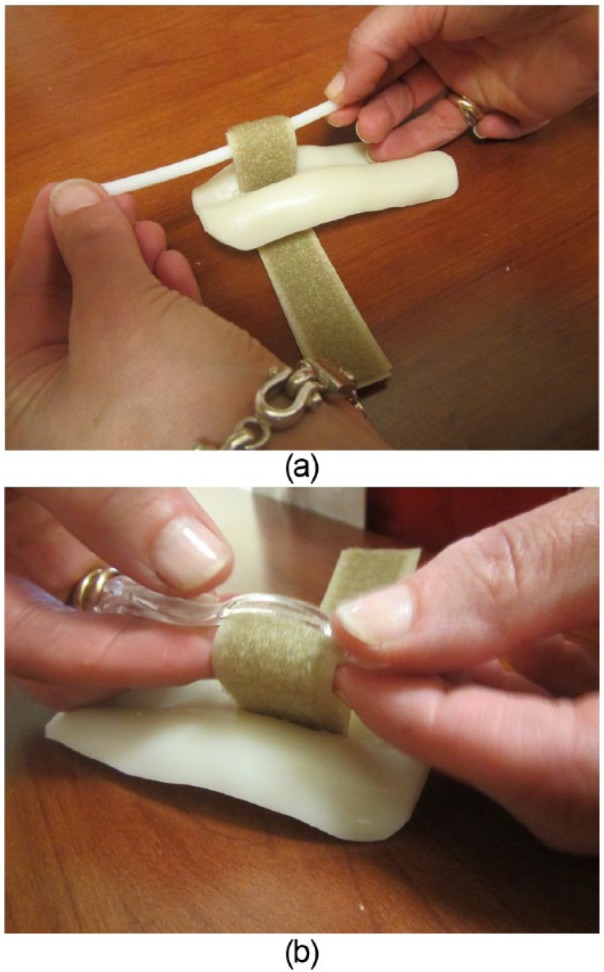
(a) Thermoplast bar passed through the Velcro loop to prevent strap from pulling through the slot. (b) The thermoplast bar is heated with a heat gun and while the thermoplast bar is still soft, the bar is bent back and crimped to itself and to the Velcro strap.
Strong has suggested an interesting “dynamic” PIP joint extension block splint using 2 bent aluminum foam-backed splints secured to the dorsal proximal and middle phalanges.4 When the digit extends, the 2 splints abut one another and block extension of the PIP joint. In practice, we have successfully used this splint, but it also has drawbacks. First, for this design to be effective, the splints must hold their specific position and relationship with one another; otherwise, the splints fail to make contact in extension, or the distal splint pistons forward and loses the extension block effect. Second, given the use of adhesive tape and the more complicated splint design, a significant amount of patient skill is required to reapply the splint for skin care. We have tried to modify the Strong splint using the thermoplast material and a Velcro strap. This design had better comfort and ease of use; however, the lack of an adhesive left this design prone to swiveling out of its critical dorsal position around the long axis of the finger. We also found that substituting Velcro strapping for adhesive taping worsens the piston effect of the distal splint. The Strong design is impressive, attractive, and functional when initially applied; however, the reality of splint maintenance for this design for the duration of treatment is a real challenge and the design has too many “moving parts.”
Technique for Splint Fabrication
The following steps outline our technique for the fabrication of a PIP extension block splint. The steps have been presented in detail to facilitate those who are producing the design for the first time. With greater experience, these steps can be modified and combined into a more expeditious process.
Materials
2.5 × 4 in. 1/8-in. thickness thermoplast material
7 to 8 in. of 1-in. wide Velcro strapping
Two 1 × 1/2 in. sticky backed Velcro tabs
D-ring or 3 in. of thermoplast bar
Splint Fabrication
Step 1
With digits extended, the involved (long finger in this example) and best matching neighboring digit (ring finger in this example) are outlined on a thermoplast sheet (Figure 1).
Figure 1.
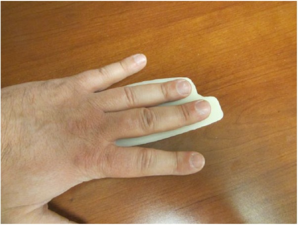
Outline of long and ring fingers on the thermoplast sheet.
Step 2
The thermoplast material is heated in a warm water bath and molded to the dorsum of the involved and neighboring digit. When molding the splint, it is helpful if the digits are flexed at the PIP joints approximately to the prescribed extension block angle (Figure 2). The splint is allowed to harden in this shape.
Figure 2.
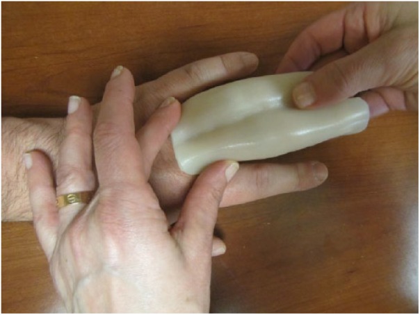
Molding of splint with digits flexed at the PIP joints.
Note. PIP, proximal interphalangeal.
Step 3
The uninvolved neighboring digit is flexed out of the way at the PIP joint and the undersurface of the splint is marked at the sulcus between the fingers at the level of the PIP joint flexion crease of the involved digit (Figure 3). This step will place the distal edge of the Velcro strap at the PIP flexion crease of the involved finger for maximum support of that joint.
Figure 3.
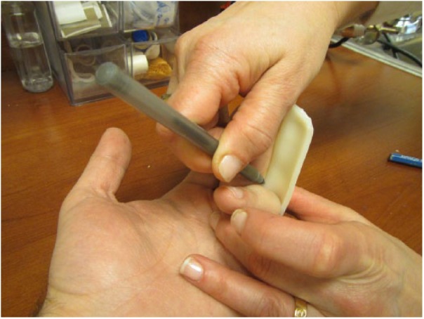
Undersurface of thermoplast splint being marked at the sulcus between the fingers at the PIP joint flexion crease of the involved digit.
Note. PIP, proximal interphalangeal.
Step 4
The 1-in. Velcro strap width is marked on the undersurface of the sulcus extending proximally from the mark made in step 3 (Figure 4).
Figure 4.
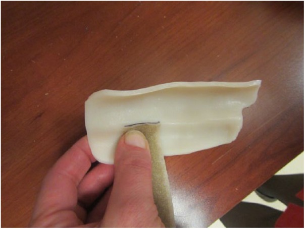
The width of the 1-in. Velcro strap being marked on the undersurface of the sulcus.
Step 5
The relatively transparent thermoplast material allows for an easy copy of the undersurface marking to the outer surface, which will be used to create the strap slot (Figure 5).
Figure 5.
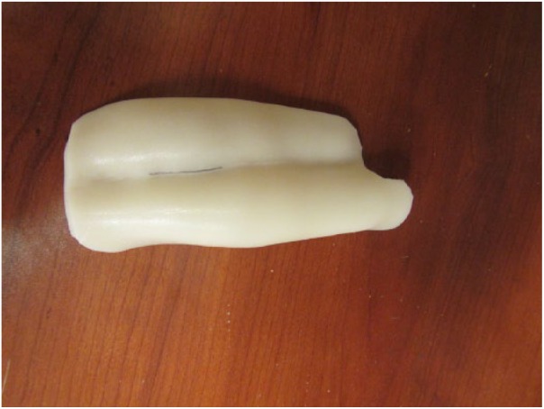
The undersurface mark is copied on the outer (dorsal) splint surface.
Step 6
Cut a slot in the splint sulcus using a utility knife (Figure 6a). Spot heating the marked area with a heat gun softens the material and makes this step easier. It is important to maintain a slot that closely matches the exact width of the Velcro strap to prevent migration of the splint. As a secondary step, the blade of scissors can be helpful to dilate the slot to help passage of the Velcro strap (Figure 6b).
Figure 6.
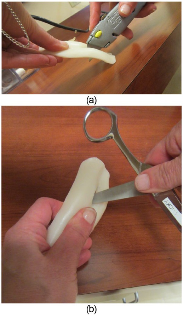
(a) Cutting of the splint at the marking (at the splint sulcus) using a utility knife. (b) Using the blade of scissors helpful to dilate the slot for passage of the Velcro strap.
Step 7
A 7- to 8-in. segment of the 1-in.-wide Velcro strap is folded in half with the fuzzy side out. The leading ends are then fed through the slot from the dorsal side (Figure 7).
Figure 7.
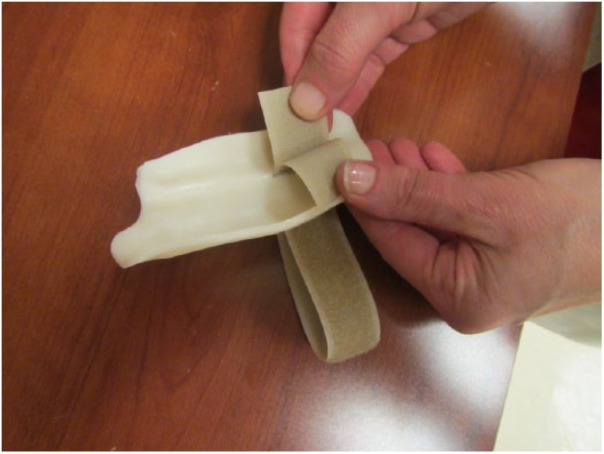
Velcro straps inserted through the dorsal side of the slot.
Step 8
To prevent the strap from pulling through the slot, a 4-in.-long heated thermoplast bar is passed into the Velcro loop (Figure 8a). The thermoplast bar is heated with a heat gun and while the thermoplast bar is still soft, the bar is bent back and crimped to itself and to the Velcro strap (Figure 8b). The crimped bar is then trimmed leaving a tab on either side of the looped Velcro. Alternatively, a small D-ring can be used to prevent strap pull-through. The Velcro strap is looped through the D-ring and the strap is stapled or stitched at the loop juncture to produce 2 strap limbs. These limbs are then passed from dorsal to volar through the slot as described.
Step 9
Pulling the Velcro straps toward the palmar side of the splint places the bar at the dorsum of the splint and stabilizes the palmar straps (Figure 9a-b). The thermoplast bar material could be spot heated to spot-weld it to the dorsal aspect of the splint.
Figure 9.
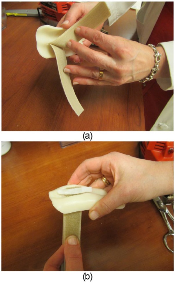
(a) Velcro straps pulled through the palmar side of the splint. (b) The bar on the dorsal side stabilizes the strap and prevents it from pulling through the splint slot.
Step 10
The splint is replaced over the dorsum of the digits with the Velcro straps between the digits (Figure 10a). One strap is pulled around the involved digit, secured to the dorsal aspect of the splint with a sticky backed Velcro tab, and trimmed to an appropriate length (Figure 10b). The other tab is pulled in the other direction around the neighboring digit and is also secured on the dorsum of the splint with its own sticky backed Velcro tab and trimmed to length (Figure 10c).
Figure 10.
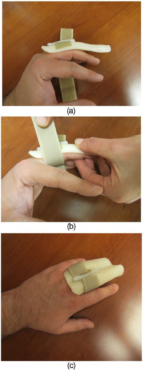
Initial fitting of the splint. (a) The two strap ends are slipped between the involved digit and the neighboring uninvolved digit. (b) One strap is pulled around the involved digit, fitted and trimmed to the appropriate length. (c) The other strap is pulled around the neighboring uninvolved digit and fitted and trimmed to the appropriate length.
Step 11
The splint is marked on the dorsal side just distal to the PIP joint extension creases for the uninvolved digit and at the distal interphalageal (DIP) joint extension creases for the involved digit (Figure 11). It is important to maintain an adequate amount of splint material between the Velcro strap slot and the more proximal of these 2 markings to avoid fracturing the splint through the strap slot.
Figure 11.
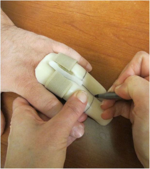
Markings are made on the dorsal side just distal to the PIP joint extension creases for the uninvolved digit and at the DIP joint extension creases for the involved digit.
Note. PIP, proximal interphalangeal; DIP, distal interphalangeal.
Step 12
Trimming is done along these markings with sharp scissors (Figure 12a-c). Sharp edges and corners are trimmed or rounded with spot heating.
Figure 12.
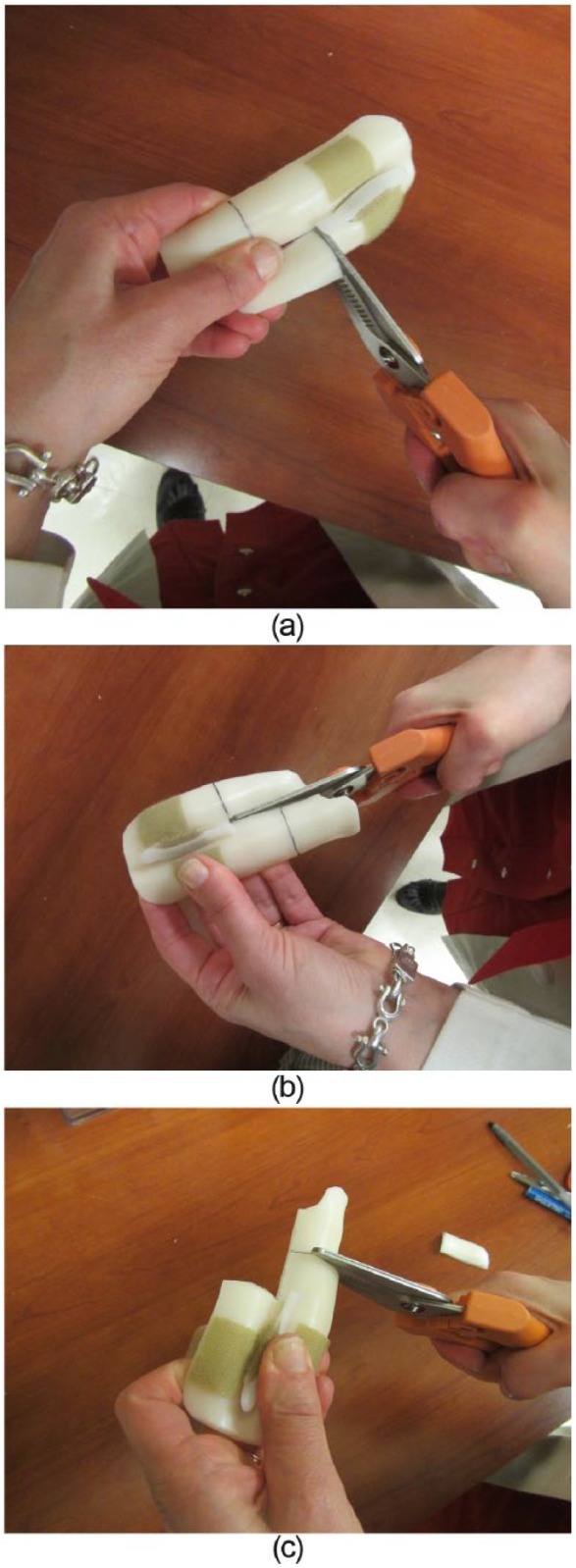
(a-c) Cutting of the markings made on the splint with sharp scissors.
Step 13
The sticky backed Velcro tab over the dorsal involved digit is marked and removed in anticipation of setting the extension block position (Figure 13). Alternatively, the placement of this sticky tab can be delayed until after setting the proper angle in step 15.
Figure 13.
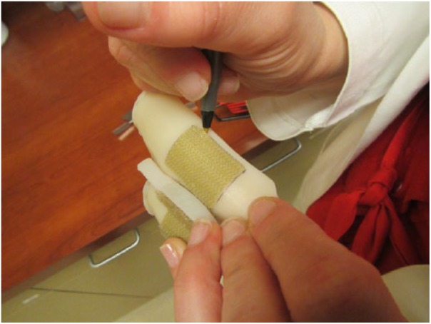
Tracing of the Velcro tab.
Step 14
A flat-surfaced goniometer will serve as the template for fine tuning the splint angle. The goniometer is secured with tape at the prescribed extension block angle (Figure 14a). The splint PIP area for the involved digit is carefully spot heated to soften the area for molding (Figure 14b). The splint is replaced over the digits and the goniometer is used to mold the proper extension block angle (Figure 14c). It is important to use the flat surface of the goniometer to produce a flat surface over the dorsal proximal phalanx and a flat surface over the dorsal middle phalanx with a true angle created between those surfaces. Flat surfaces produce optimum bone support, better splint fit, and better angular control across joints compared with curved splints with a poorly defined angle.
Figure 14.
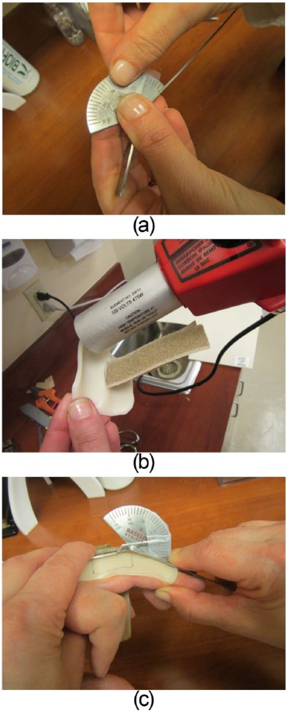
Fine tuning of splint angle. (a) Goniometer angle is set with tape. (b) Splint PIP area of the involved digit is softened with spot heating. (c) Flat surfaces of goniometer are placed over the softened splint to mold proper extension block angle.
Step 15
Once the splint has cooled with its proper shape, the previously removed Velcro tab is replaced and the strap fit is reviewed. The mismatch of the PIP flexion creases between the involved digit and the neighboring digit may necessitate cutting a scallop at the distal edge of the Velcro strap for the neighboring digit (Figure 15a-b).
Figure 15.
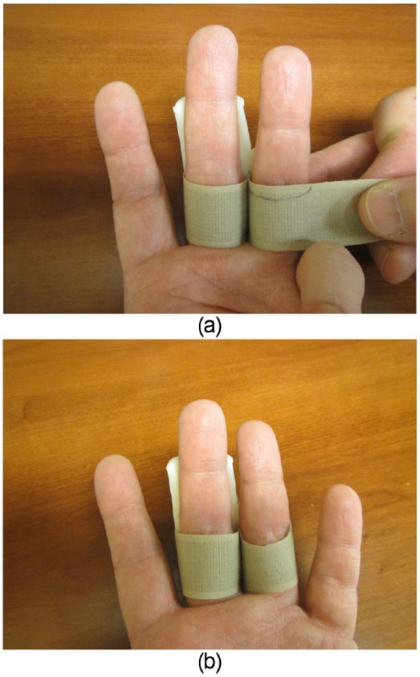
Strap fitting. (a) Mismatch of PIP flexion crease is marked on strap. (b) Scalloped strap section is cut away as necessary to allow for full PIP flexion.
Final Splint
The splint should allow for full flexion and a proper extension block of the involved digit (Figure 16a-b). The distal edge of the Velcro strap should be at the PIP joint flexion crease for the involved digit without impeding PIP joint flexion. The neighboring digit should contribute to the provision of a stable base for the splint while maintaining unimpeded motion. During follow-up care, the degree of extension blocking can be adjusted with spot heating using a heat gun. If static splinting of the digit at a specific degree of PIP flexion is desired, a distal strap can be added to hold the digit statically against the splint surface in a desired position of flexion.
Figure 16.
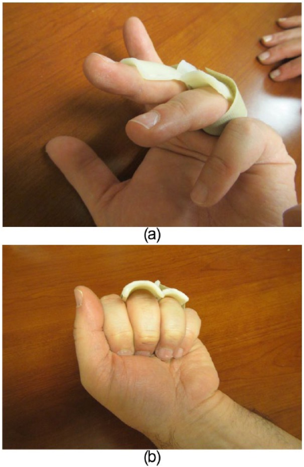
Final fitting of splint. (a) Ring finger is slightly flexed to demonstrate extension block for the long finger. (b) Final splint should allow for unimpeded digital flexion.
In cases of PIP joint fracture-subluxations, usually after the first 3 weeks of successful maintenance of PIP joint reduction, the degree of PIP flexion can be gradually adjusted into a straighter position using the technique described in step 14. Typically, the degree of PIP flexion is decreased by 10° per week with radiographs obtained in the newly adjusted splint.
Expected Outcomes
PIP joint injuries can be quite prone to stiffness. With the intent of minimizing the risk of PIP joint stiffness, the use of a PIP extension block splint can be a helpful technique for regaining joint flexibility through a safe zone of motion.
Complications
The use of a PIP extension block splint requires careful follow-up to evaluate patient compliance, skin integrity, and joint reduction. Although this splint is designed to make the application of this type of splint more practical, it does not eliminate the need for proper surveillance.
This splint is relatively easy for patients to handle, but it is possible that some patients may still have trouble with its use or not have a proper understanding of the schedule for its wear or its positioning. In addition, any splinting protocol has a risk of skin breakdown and maceration. The risks for these types of skin problems will vary from patient to patient depending on their skin characteristics. Finally, the use of a PIP extension block splint is intent on maintaining PIP joint reduction. The reduction of the PIP must be checked frequently with periodic radiographs especially when periodic adjustments are made to the splint to gradually increase the allowance of PIP extension.
Generally, we have had patients return for weekly evaluations for the first 4 to 6 weeks after initiating the use of the splint for PIP fracture-subluxations. These weekly evaluations, radiographs, and patient re-education have worked well with most patients.
Acknowledgments
Special thanks to Cynthia Watkins, PT, CTH, for her help with the article’s photos.
Footnotes
Ethical Approval: This particular study was exempt from IRB approval in agreement to our institutional policy.
Statement of Human and Animal Rights: All procedures followed were in accordance with the ethical standards of the responsible committee on human experimentation (institutional and national) and with the Helsinki Declaration of 1975, as revised in 2008.
Statement of Informed Consent: Informed consent was obtained when necessary.
Declaration of Conflicting Interests: The authors declared no potential conflicts of interest with respect to the research, authorship, and/or publication of this article.
Funding: The authors received no financial support for the research, authorship, and/or publication of this article.
References
- 1. Calfee RP, Kiefhaber TR, Sommerkamp TG, Stern PJ. Hemi-hamate arthroplasty provides functional reconstruction of acute and chronic proximal interphalangeal fracture-dislocations. J Hand Surg. 2009;34(7):1232-1241. [DOI] [PubMed] [Google Scholar]
- 2. McElfesh EC, Dobyns JH, O’Brien ET. Management of fracture-dislocation of the proximal interphalangeal joints by extension-block splinting. J Bone Joint Surg Am. 1972;54(8):1705-1711. [PubMed] [Google Scholar]
- 3. McPhee SD. Extension block splinting for the proximal interphalangeal joint. Am J Occup Ther. 1987;41(6):389-390. [DOI] [PubMed] [Google Scholar]
- 4. Strong ML. A new method of extension-block splinting for the proximal interphalangeal joint-preliminary report. J Hand Surg Am. 1980;5(6):606-607. [DOI] [PubMed] [Google Scholar]
- 5. Weber DM, Kellenberger CJ, Meuli M. Conservative treatment of stable volar plate injuries of the proximal interphalangeal joint in children and adolescents-aprospective study. Pediatric Emerg Care. 2009;25(9):547-549. [DOI] [PubMed] [Google Scholar]


