

Abstract
BACKGROUND
Polymethylmethacrylate (PMMA) is the most common material used to fabricate interim fixed partial denture (FPD). Several attempts have been made to improve fracture strength of this material with various methods of reinforcement, but its effect on the fracture resistance of interim FPD was not evaluated.
METHOD
The study was designed in two stages. In the first stage various methods of reinforcement (glass fibre, polyethylene, combination of glass and polyethylene, and stainless steel) for interim FPD of PMMA were used and its effect on the fracture resistance of interim FPD was evaluated by three point bending test using universal testing machine. In the second stage, fibres which showed the highest fracture resistance value was used to ascertain the most appropriate site of placement for reinforcing interim FPD. Comparisons were made with analysis of variance.
RESULTS
Stainless steel and glass fibres showed significantly higher fracture resistance value than polyethylene alone or mixed with glass fibres (P < 0.001). Fibre placement in the occlusal third region of the pontic resulted in higher fracture resistance than the other locations (P < 0.05).
CONCLUSION
There was a definite improvement in the fracture resistance after reinforcement with fibres and stainless steel. The occlusal third region of the pontic is the most appropriate site of placement for reinforcement in interim FPD.
Key Words: fibre reinforcement, polymethylmethacrylate
INTRODUCTION
Rehabilitation of partially edentulous patients using fixed partial denture (FPD) is a well-established treatment protocol since many decades. These FPDs require a laboratory phase of fabrication that varies from days to weeks. A dimensionally stable, strong, and accurate interim restoration is an important component of this treatment modality. These interim restorations provide pulpal protection, positional stability, occlusal function, strength, and aesthetics.
Polymethylmethacrylate (PMMA) is the most common material used to fabricate interim FPDs. This material lacks sufficient strength and hence various methods are being used for reinforcing it in the past like glass fibres, carbon fibres, kevlar fibres, polyethylene fibres, and stainless steel wire.1, 2, 3, 4 To date, little information is available in the literature on fracture resistance of reinforced PMMA temporary crown and bridge materials. It is also not clear as to how the site of placement of fibre reinforcement, influences the fracture resistance of temporary crown and bridge materials. Therefore, this study was undertaken to evaluate the fracture resistance of interim FPDs using different types of fibre reinforcements and also to determine the most appropriate site of reinforcement of interim FPDs fabricated from PMMA.
MATERIALS AND METHOD
This study was designed in two stages. In the first stage various methods of reinforcement for interim FPDs made up of PMMA were evaluated. During the second stage, favourable sites of placement to strengthen the interim FPDs were evaluated. There were five groups of ten samples each namely the group 1 (unreinforced, control group), group 2 (glass fibre-reinforced), group 3 (polyethylene fibre-reinforced), group 4 (glass and polyethylene mixed fibre) and group 5 (stainless steel reinforced).
Samples were tested for fracture resistance in an Instron universal testing machine. The maximum load causing the initial fracture and fracture resistance were calculated. The mean and standard deviation for each group were determined. The data was analysed for differences using one way analysis of variance (ANOVA) (The Tukey's standardised range test) to determine the statistically significant differences between the means.
A precision metallic die (master die) was specially fabricated in brass. The die had a rectangular base and two abutments representing a mandibular second premolar and mandibular second molar fixed on to the base. For fabrication of the master die, the abutments were first prepared on typhodont model (Columbia Dentoform Corporation, USA) with a 1 mm wide shoulder finish line and a uniform taper of 6° and then cast in brass and polished. The two abutments were then placed in a metal base so that the inter-abutment distance measured from the distal of premolar to the mesial of the molar was 10 mm apart. The intervening space was also cast with brass metal to simulate the edentulous ridge in between.
An all-metal FPD with a bar sanitary pontic was made on this precision master die (Figure 1). The mesio-distal and buccolingual width of the connector was kept at 3.5 mm in width and the occlusocervical dimension of the connector was kept at 2.5 mm. A mild steel custom tray with T shaped handle was fabricated over the master die by precise machining to fit onto the rectangular base. After block-out of all the dead space below the three-unit FPD on the master die, a polyvinyl siloxane (PVS) impression (Virtual 380, Ivoclar Vivadent, Liechtenstein) was then made. Test specimens were then made with the help of this impression on the same day to ensure that all interim FPDs had the same dimensions under uniform conditions. By trial and error method, it was found that 1.5 g of autopolymerizing acrylic powder was sufficient to fill the putty index leaving slight excess. Pre-weighed packets of autopolymerizing PMMA resin powder with pre-measured 1.5 cc of liquid were then used for each group of the samples and the average thickness of provisional restorations were kept around 2 mm. Fifty test specimens were then made with the help of this impression on the same day by the same operator to ensure that all interim FPDs had the same dimension under uniform conditions. The samples were then divided into five groups of 10 samples each, i.e. group 1: control unreinforced group; group 2: reinforced with glass fibre; group 3: reinforced with polyethylene fibre; group 4: reinforced with glass and polyethylene fibre mix; and group 5: reinforced with 1 mm diameter stainless steel wire.
Figure 1.
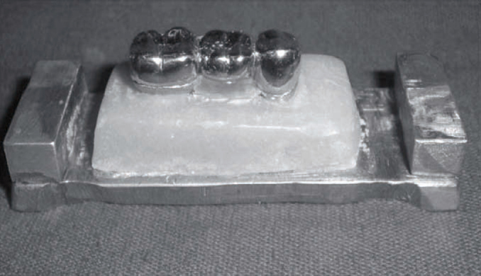
The three-unit metal fixed partial denture on the master die.
For the unreinforced specimens the polymer and monomer of PMMA resin (DPI, Mumbai, India) was mixed following manufacturers recommendations and poured in to the PVS impression. The die was coated with thin layer of vaseline as separating medium. The impression with the resin mixture was then inverted over the rectangular base of the die and left to polymerize for 15 minutes under uniform pressure. After 15 minutes, the tray was removed and the three-unit interim FPD sample was carefully separated from the impression, trimmed and polished. Ten such samples were made for this group.
For glass fibre-reinforced group, the 1 mm thick E glass fibres (Ever Stick®, Stick Tech Ltd, Turku, Finland) were pre-cut to 10 mm in length. Monomer was used to wet these fibres. Polymethylmethacrylate resin was divided into two parts. One-third part of resin was hand mixed and used to stabilise the glass fibres in the occlusal third of the pontic and the remaining two-third part of the resin was then mixed and poured in to the impression. Rest of the procedure was same as that of control group. For polyethylene fibre (Ribbond Inc, Seattle, WA) reinforced group, procedures followed were same as that in glass fibre-reinforced group. For polyethylene and glass fibre mixed group, 10 mm pre-cut glass fibre and polyethylene ribbon, of 0.5 mm thickness were used. Monomer liquid and small amount of polymer powder were also used to wet these fibres. The resin was hand mixed using similar methodology as in group 2 and the position of the fibre stabilised in the occlusal third of the pontic. For SSW reinforced group (KC Smith and Company, UK) 1.0 mm diameter stainless steel pre-cut to 10 mm in length was used and the rest of the procedure was same as that of reinforced groups.
Fracture resistance of the samples was evaluated using three point bending test with the help of a universal testing machine (Instron Corporation, Model 4204, Canton, Mass). Each interim FPD sample was firmly seated with hand pressure on the brass master die and held on the universal testing machine. The test samples were loaded with a 6.36 mm diameter steel ball placed on the machine arm loaded in the region of the central fossa of the pontic with a crosshead speed of 5 mm/minute till the fracture occurred (Figure 2). The load causing the initial fracture was recorded. All the data was recorded, tabulated and subjected to statistical analysis. The mean and standard deviation for each group were determined. The data was analysed for differences using one way ANOVA (P < 0.001). The Tukey's standardised range test (HSD which is a type of ANOVA test) was used.
Figure 2.

Testing on Instron machine.
From the results of the first stage of the study, the group which showed the highest fracture resistance was chosen for the second stage. Since glass fibres showed the highest fracture resistance, they were used for further study of favourable site of placement. Ten specimens each were made with fibres restricted from one connector to the other i.e. from distal end of premolar abutment to mesial end of molar abutment in three different locations, i.e. occlusal, middle, and cervical third of the pontic. For the occlusal third group, glass fibre was pre-cut to 10 mm and wetted with monomer before placement. The resin mixture was divided into two parts and similar methodology of positioning the fibres in the occlusal third of the pontic region was followed as in first stage. For the middle third group and cervical third group the same procedures were followed except for the location of the fibres. The testing was carried out similar to first stage of the study. The data was recorded, tabulated and analysed using one way ANOVA (P < 0.05) to determine statistically significant differences between the means.
RESULTS
For the first stage of the study, the mean and standard deviation of each group is shown in Table 1. The mean fracture resistance for the unreinforced group control was 7.84 ± 1.33 MPa; for glass fibres 13.54 ± 4.98 MPa; for polyethylene fibres 11.83 ± 3.45 MPa; for glass and polyethylene mixed 11.73 ± 3.24 MPa; and for stainless steel wire was 14.09 ± 2.06 MPa.
Table 1.
Comparison of fracture resistance strength in Stage I.
| Methods of reinforcements | Fracture resistance (MPa) Mean ± SD (n = 10) |
|---|---|
| Control | 7.84 ± 1.33 |
| Reinforced with glass fibres | 13.54 ± 4.98 |
| Reinforced with polyethylene | 11.83 ± 3.45 |
| Reinforced with glass and polyethylene mixed fibres | 11.73 ± 3.24 |
| Reinforced with stainless steel wire | 14.09 ± 2.06 |
| Fvalue | 5.62 |
| P value | < 0.001 |
The Tukey's standardised range test (which is a type of ANOVA test) revealed that all reinforced groups had significantly greater fracture resistance than the unreinforced resin controls (Figure 3). Glass fibre and SSW reinforcement showed highly significant values compared to the unreinforced group. The fracture resistance of glass and SSW wire were significantly greater than that of glass and polyethylene mixed and polyethylene alone (P < 0.001). For the second stage of the study, the results showed that the placement of the reinforcement in the occlusal third of the pontic resulted in higher fracture resistance which was significantly higher (P < 0.05) than in the other locations (Figure 4 and Table 2). The mean ± SD for glass fibres in occlusal, middle, and cervical third were 14.20 ± 3.49, 10.05 ± 3.61 and 11.80 ± 2.13, respectively.
Figure 3.

Box plot showing comparison of fracture resistance strength in Stage I.
Figure 4.

Box plot showing comparison of fracture resistance strength in Stage II.
Table 2.
Comparison of fracture resistance strength in Stage II.
| Methods of placement of fibres | Fracture resistance strength (MPa) Mean ± SD (n = 10) |
|---|---|
| Occlusal third | 14.20 ± 3.49 |
| Glass middle third | 10.05 ± 3.61 |
| Glass cervical third | 11.80 ± 2.13 |
| Fvalue | 4.38 |
| P value | < 0.05 |
DISCUSSION
Materials commonly used to fabricate interim restorations are polymethyl methacrylates, polyethylmethacrylates or n-polybutylmethacrylates (PBMA), urethanedimethacrylates, bisacryl composites, and epimine resins. Autopolymerizing PMMA has been in routine use since 1930s and remains the most frequently used material for fabrication of interim restorations.5, 6 One of the most common failures of PMMA interim FPDs is fracture. In spite of our best efforts in designing and material modifications, they fail leading to discomfort and time loss. Thus fracture resistance of interim FPD material is an important factor and should be considered prior to selecting a provisional material for the clinical success.7 Several attempts have been made to improve physical properties of resin based materials with various fibre reinforcements. Such reinforcements reduce flexure, increase retention and fracture toughness, and increase structural integrity. The glass fibres incorporated into PMMA considerably increase transverse strength of PMMA. There was evidence from dynamic in-vitro tests that glass fibre reinforcement increased fatigue resistance of dental appliance up to 100 times.8
Various studies2, 3, 4, 5 have been described in the literature to discover the ideal material to reinforce provisional restorative materials. But none of these studies provide a conclusive idea about the material of choice. Therefore this study was undertaken to evaluate the fracture resistance of interim FPDs using different types of fibre reinforcements. The glass fibres used in the study (everStick®, Stick Tech Ltd, Turku) are silanized E-glass fibres pre-impregnated with porous polymer and is formed of a large number of unidirectional glass fibres. Ribbond® consists of cold plasma-treated polyethylene fibres. Wetting the fibres with monomer-polymer mix has been commonly used method to ensure adequate impregnation and was used in the study too. Similar dimension stainless steel wire was also used for reinforcement. The three-unit FPDs samples were loaded with a stainless steel ball on the central fossa on a universal testing machine. The fracture resistance values were thus recorded. The fibres which showed the best results in the Stage I of the study were selected for the Stage II. In this stage three different site of placement of fibres, i.e. the occlusal, middle, and cervical third of the pontic region of the three-unit interim FPDs were selected, and then the fracture resistance was tested.
Results of Stage I study indicated that among all the fibres selected, the fracture resistance values of glass fibres were statistically highly significant when compared to unreinforced sample (P < 0.001). Hence, glass fibres were chosen for the second stage of the study. Results of the second stage of the study suggested that placement of fibres in the occlusal third of the pontic region of the three-unit FPD sample showed the best fracture resistance values. Statistical analysis showed significant results (P < 0.05).
In our study, the fracture resistance of interim FPDs made of PMMA is definitely improved after reinforcement with fibres and SSW. Adequate adhesion of the fibres to the polymer matrix is one of the most probable reasons for increased fracture resistance of the polymer fibre composite.9, 10 The reinforcing effect of glass fibres was more effective than that of polyethylene fibres, and this was attributed to the difficulty of obtaining good adhesion between ultra-high modulus polyethylene fibres and the resin matrix.11 The results of the second stage revealed that placing the fibres at the occlusal third of the pontic gave the highest fracture resistance values. It is suggested that reinforcement at the cervical third of the pontic region (area of tension under the occlusal load) showed higher fracture toughness values.12, 13 This was not in agreement with the results obtained in this study. This can be explained because interim restoration resin, like most brittle materials, has a greater compressive than tensile strength. Therefore, fracture is usually initiated in the tension side of the restoration, which will be in the cervical third of the pontic. Many investigators have confirmed the reinforcing effect of fibres on different polymer types.2, 14 This was in agreement with the results of this study, which revealed that all tested fibres increased the fracture resistance of interim restoration resins. By placing fibre in the occlusal third, the resistance to fracture of the restoration is increased, because the fibre will stop propagation of the initiating fracture through the restoration. However, the reasons for this needs to be investigated using more detailed methodology. Other areas which need to be researched include the effect of following factors such as quantity of fibres, direction of fibres, orientation of fibres, type of interim luting agent, and connector size on fracture resistance. However, these results may provide a rational clinical protocol for the fabrication of fibre-reinforced interim FPD.
CONCLUSION
Within the limitations of the current study, the following can be concluded:
-
1
All reinforcements evaluated produced an increase in fracture resistance (P < 0.001).
-
2
Placement of reinforcement in the occlusal third of the interim FPD produced the greatest fracture resistance (P < 0.05).
The overall results of the in vitro study carried out showed that use of glass fibre and, to a lesser extent, stainless steel wire, is an effective method to reinforce interim restorations made of PMMA resins. The occlusal third of the pontic region from mesial to distal end of the connector is the best site of placement of the fibre for reinforcing the PMMA interim restorative resin. Further in vivo studies using this methodology are recommended to substantiate these results so that the ideal restorative protocol can be determined for clinical success.
Intellectual Contributions of Authors
Study concept: Col M Viswambaran, Surg Lt Cdr Anita Kapri
Drafting and manuscript revision: Col M Viswambaran, Lt Col Manjit Kumar (Retd)
Statistical analysis: Col DSJ D'Souza, Col M Viswambaran
Study supervision: Col DSJ D'Souza, Surg Lt Cdr Anita Kapri
CONFLICTS OF INTEREST
None identified.
REFERENCES
- 1.Bowman AJ, Manley TR. The elimination of breakages in upper dentures by reinforcement with carbon fibre. Br Dent J. 1984;156:87–89. doi: 10.1038/sj.bdj.4805275. [DOI] [PubMed] [Google Scholar]
- 2.Hamza TA, Rosenstiel S, El-Hosary MM, Ibraheem RM. Fracture resistance of fiber reinforced PMMA Interim fixed partial dentures. J Prosthodont. 2006;15:223–228. doi: 10.1111/j.1532-849X.2006.00110.x. [DOI] [PubMed] [Google Scholar]
- 3.Solnit GS. The effect of methyl methacrylate reinforcement with silane treated and untreated glass fibers. J Prosthet Dent. 1991;66:310–314. doi: 10.1016/0022-3913(91)90255-u. [DOI] [PubMed] [Google Scholar]
- 4.Vallittu PK. A review of methods used to reinforce polymethyl meth-acrylate resins. J Prosthodont. 1995;4:183–187. doi: 10.1111/j.1532-849x.1995.tb00338.x. [DOI] [PubMed] [Google Scholar]
- 5.Federick DR. The provisional fixed partial denture. J Prosthet Dent. 1975;34:520–524. doi: 10.1016/0022-3913(75)90039-6. [DOI] [PubMed] [Google Scholar]
- 6.Carroll CE, von Fraunhofer JA. Wire reinforcement of acrylic resin prostheses. J Prosthet Dent. 1984;52:639–641. doi: 10.1016/0022-3913(84)90132-x. [DOI] [PubMed] [Google Scholar]
- 7.Haselton DR, Diaz-Arnold AM, Vargas MA. Flexural strength of provisional crown and fixed partial denture resins. J Prosthet Dent. 2002;87:225–228. doi: 10.1067/mpr.2002.121406. [DOI] [PubMed] [Google Scholar]
- 8.Tacir IH, Kama JD, Zortuk M, Eskimez S. Flexural properties of glass fibre reinforced acrylic resin polymers. Aust Dent J. 2006;51:52–56. doi: 10.1111/j.1834-7819.2006.tb00401.x. [DOI] [PubMed] [Google Scholar]
- 9.Vallittu PK. The effect of glass fiber reinforcement on fracture resistance of a provisional fixed partial denture. J Prosthet Dent. 1998;79:125–130. doi: 10.1016/s0022-3913(98)70204-5. [DOI] [PubMed] [Google Scholar]
- 10.Hamza TA, Rosenstiel S, El-Hosary MM, Ibraheem RM. The effect of fiber reinforcement on the fracture toughness and flexural strength of provisional restorative resins. J Prosthet Dent. 2004;91:258–264. doi: 10.1016/j.prosdent.2004.01.005. [DOI] [PubMed] [Google Scholar]
- 11.Piovesan EM, Demarco FF, Piva E. Fiber reinforced fixed partial dentures: a preliminary retrospective clinical study. J Appl Oral Sci. 2006;14:100–104. doi: 10.1590/S1678-77572006000200007. [DOI] [PMC free article] [PubMed] [Google Scholar]
- 12.Freilich MA, Meiers JC, Duncan JP, Eckrote KA, Goldberg AJ. Clinical evaluation of fiber reinforced fixed bridges. J Am Dent Assoc. 2002;133:1524–1534. doi: 10.14219/jada.archive.2002.0084. [DOI] [PubMed] [Google Scholar]
- 13.Geerts GAVM, Overturf JH, Oberholzer TG. The effect of different reinforcement on the fracture toughness of materials for interim restorations. J Prosthet Dent. 2008;99:461–467. doi: 10.1016/S0022-3913(08)60108-0. [DOI] [PubMed] [Google Scholar]
- 14.Vallittu PK. Comparison of the in-vitro fatigue resistance of an acrylic resin removable partial denture reinforced with continuous glass fibres or metal wires. J Prosthodont. 1996;5:115–121. doi: 10.1111/j.1532-849x.1996.tb00285.x. [DOI] [PubMed] [Google Scholar]