Abstract
Objective:
There is no definitive study comparing stress distribution around two versus three implants in implant-retained overdentures with different cantilever length. The purpose of this finite element study was to evaluate stress pattern around the implants of the 2 or 3 implant- supported mandibular overdenture with different cantilevered length.
Materials and Methods:
The models used in this study were 2 and 3 implant-supported overdenture with bar and clip attachment system on an edentulous mandibular arch. Each model was modified according to cantilever length (0 mm, 7 mm, and 13 mm); thus, 6 models were obtained. The vertical load of 15 and 30 pounds were applied unilaterally to the first molar and 15 pounds to the first premolar, and the stress in bone was analyzed.
Results:
With increasing cantilever length, no similar stress pattern changes were observed in different areas, but in most instances, an increase in cantilever length did not increase the stress around the implant adjacent to cantilever.
Conclusions:
Within the limitations of this study, it can be concluded that increasing of cantilever length in mandibular overdentures retained by 2–3 implants did not cause distinct increasing in stress, especially around the implant adjacent to cantilever, it may be helpful to use cantilever in cases of mandibular overdenture supported by splinted implants with insufficient retention and stability. Based on the findings of this study, optimal cantilever length in mandibular overdenture cannot be determined.
Keywords: Cantilever, finite element analysis, overdenture, stress
INTRODUCTION
Implant-retained overdenture offers a convenient treatment for edentulous patients.[1,2] Usually, one to five implants can be used to support a mandibular overdenture between the mental foramina.[3,4,5] Using two or three implants for retaining and stabilizing dentures has cost benefits for the patient.[3,6,7] Mandibular overdentures supported by implants placed between the mandibular foramina restrict the length of the distally cantilevered components to minimize torque-related stress to the supporting implants.[8]
Inserting three implants and splinting them with a connecting bar are more congruent with the ridge shape. In this situation, the middle implant can act as an indirect retainer for the prosthesis.[3,9] This strategy can be useful when patients rehabilitated by two-implant supported overdentures report constant and obvious denture rotation around the fulcrum line.[5]
The influence of implant number and cantilever design on stress distribution on bone has not been sufficiently assessed for the mandibular overdentures.[10] In a clinical study by Semper et al.,[11] no influence of the length of cantilever extensions on crestal bone loss was found. The results indicate that prostheses with distal bar extensions up to 12 mm are an adequate treatment option for edentulous patient. The results of a study by Elsyad et al.[12] recommended the use of the 7 mm cantilevered bars in two implants-supported mandibular overdentures as it demonstrated the lowest magnitude of strains with no significant differences between peri-implant sites.
Because cantilever length is considered to influence forces transferred to implants and bone and has direct clinical effect on marginal bone loss, so it is important that its effects on stress transfer to be investigated.[13,14] Regardless of the length of the cantilever, the greatest tensions will always be located on the region of the implant closest to the load application point.[15] Several renowned authors have stated that to decrease the lever arm, the length of the cantilever in mandible should not exceed 20 mm.[16,17,18] So far, others said that the length of the cantilever should not exceed the anteroposterior length of the area where the implants are distributed, and an implant distribution with an anteroposterior length > 11.1 mm will produce a cantilever length which is adequate to promote satisfactory biomechanics, in addition to producing a favorable esthetic and phonetic result.[13,19] Clinically, calculated maximum cantilever length was defined as the length that would not cause gold screw loosening or fatigue failure.[19] However, without cantilevers, there is less retention and stability as well as the reduced support of the denture base over sensitive anatomic structures.[20]
However, there is no definitive study comparing stress distribution around two versus three implants in implant-retained overdentures with different cantilever length. The aim of this finite element study was to evaluate the influence of bar cantilever in different length on stress distribution in the bone surrounding the two and three implants-supporting mandibular overdentures.
MATERIALS AND METHODS
In this in vitro study, the experimental designs of simulated 2- and 3-implant-retained overdenture models were fabricated.[21] For this purpose, two acrylic models of an edentulous mandible were fabricated with a clear acrylic resin (Meliodent Multicryl, Heraeus-kulzer GmbH, Wehrheim, Germany). The configuration of the bone was duplicated by impression making from an edentulous mandibular skeleton. In the first model, three screw type implants and in the second one, two implants (Biohorizons Internal; BioHorizons Implant Systems Inc., Birmingham, Alabama, USA), 4 mm × 10.5 mm were embedded in the interforaminal region of the acrylic model using a dental surveyor (Ney Surveyor; Dentsply Intl, York, PA, USA).
In the models, the implants were vertically oriented, perpendicular to the occlusal plane, and parallel to each other. In the first model, the inter-implant distance was 12 mm. One implant was placed in the midline of the arch, and the others were placed approximately in the canine regions. In the other model, the inter-implant distance was 22 mm, and each of implants had an 11 mm distance from midline. Custom Cast abutments (4.5, PGCAH; BioHorizons Implant Systems Inc., Birmingham, AL 35243 USA) were placed on each implant. A connecting bar (Egg-shaped Dolder bar-Micro, Straumann, Basel, Switzerland) was fabricated from a base metal alloy (Biosil-F; Degudent GmbH, Hanau, Germany). The cantilever bars for each model was considered with 7 mm length.
Two complete overdentures containing clip attachments were fabricated on these bar attachment models by conventional dental laboratory techniques. One clip was positioned in each bar, and there was not any clip on cantilevers, so one clip in 2 implant-retained models and two clips in three implant-retained models were used. There was a spacer between bar and each retentive clip (Straumann, Basel, Switzerland).
The three-dimensional geometry of the whole above-mentioned system was scanned and digitized using ATOS II (Triple Scan) scanning technology (GOM mbH, Braunschweig, Germany) and ATOS Viewer (Version v6.3.0) software (GOM, Germany). The resultant dense point cloud was transferred to CATIA modeling software (BM, Kingstone, NY, USA). The mucosa and cortical bone were reproduced as a 2 mm and 2.5 mm layer, respectively [Figure 1].
Figure 1.
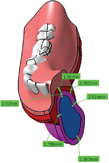
Three-dimensional model of mandible plus overdenture
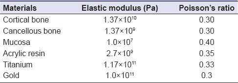
To decrease analytical problems, the implants were considered as flat cylinders. The implant-bone interface was assumed to be completely bonded (fully osseointegrated condition). There was a tolerance between the overdenture and the bar and mucosa. All materials were assumed linear, elastic, and isotropic; their properties were taken from the literature [Table 1].[15,22,23,24,25]
Table 1.
Table of material properties
In the models, three lengths of cantilever (0–7–13 mm) were defined in the computerized modeling. Stress analysis was performed using the FE software ABAQUS v6.9 (ABAQUS Inc., Providence, RI, USA). In all situations, an arbitrary 15-pound vertical and unilateral load representing the masticatory force was applied to the distal occlusal fossa of the first premolar of the prosthesis. Furthermore, vertical loads of 15 and 30 pounds were applied unilaterally to the central fossa of the first molar.[26] Stress distribution was assessed around the implants and the edentulous ridge according to implants number and cantilevered length.
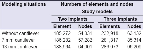
Table 2 represents numbers of elements and nodes in all study models. The analysis was performed on a computer with Windows Xp/AMD-Athlone™ 64 Processor 3200+/CPU: 2.00 GHz/RAM: 2 GB.
Table 2.
The numbers of elements and nodes in two study models
RESULTS
Stress values of models with two and three implants were summarized in Tables 3 and 4, respectively.
Table 3.
Stress values (MPa) in models with two implants

Table 4.
Stress values (MPa) in models with three implants

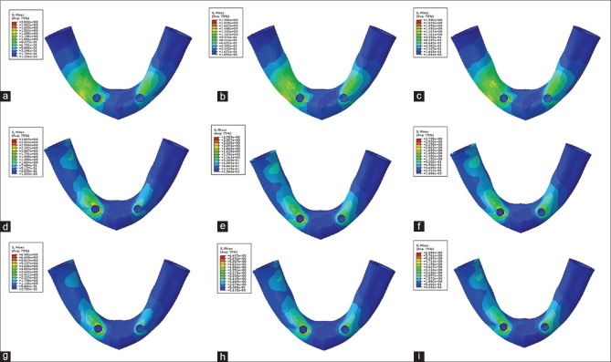
Stress distribution for 15-pound force in premolar region of models with two implants is shown in Figure 2a–c.
Figure 2.
Pattern of stress distribution for 15-pound force in premolar region of models with two implants: (a) without cantilever, (b) with 7 mm cantilever, and (c) with 13 mm cantilever. Pattern of stress distribution for 15-pound force in molar region of models with two implants: (d) without cantilever, (e) with 7 mm cantilever, and (f) with 13 mm cantilever. Pattern of stress distribution for 30-pound force in molar region of models with two implants (g) without cantilever, (h) with 7 mm cantilever, and (i) with 13 mm cantilever
Stress analysis revealed that the highest value of the stress was seen in the distal bone adjacent to the ipsilateral implant. With increasing cantilever length, there was not any important change in the stress distribution pattern. The highest stress in the posterior edentulous ridge was observed in the premolar area and by moving to more distal regions, the resultant stress was decreased.
Stress distribution for 15-pound force in molar region of models with two implants is shown in Figure 2d–f.
Stress analysis pattern in this region was different from the premolar region. With increasing cantilever length, there was not any important change in the stress distribution pattern. However, the widths of high-stress areas were increased. The highest stress in the posterior edentulous ridge was observed in the distal area of ipsilateral implant and in the premolar area.
Stress distribution for 30-pound force in the molar region of models with two implants is shown in Figure 2g–i.
This stress distribution pattern was similar to the one observed when the 15-pound force was used in the molar region.
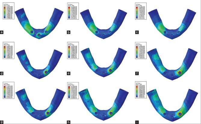
Stress distribution for 15-pound force in premolar region of models with three implants is shown in Figure 3a–c.
Figure 3.
Pattern of stress distribution for 15-pound force in premolar region of models with three implants: (a) without cantilever, (b) with 7 mm cantilever, and (c) with 13 mm cantilever. Pattern of stress distribution for 15-pound force in molar region of models with three implants: (d) without cantilever, (e) with 7 mm cantilever, and (f) with 13 mm cantilever. Pattern of stress distribution for 30-pound force in molar region of models with three implants (g) without cantilever, (h) with 7 mm cantilever, and (i) with 13 mm cantilever
Stress analysis revealed that in this situation, the stress distribution pattern around the middle implant was different from other regions. Stress distribution patterns in other regions were similar, and the highest value was seen in the distal bone adjacent to the ipsilateral implant. With increasing cantilever length, there was not any important change in the stress distribution pattern. The highest stress in the posterior edentulous ridge was observed in the premolar area and by moving to more distal regions, the resultant stress was decreased.
Stress distribution for 15-pound force in molar region of models with three implants [Figure 3d–f].
Stress pattern analysis pattern in this region was different from the premolar region. The highest stress was seen in the bone surrounding the contralateral implant. In this situation, the stress distribution pattern at the contralateral implant was clearly different from other regions. The stress distribution patterns in other regions were nearly similar. With increasing cantilever length form 0 mm to 7 mm, the widths of high-stress areas were increased. However, with increasing cantilever length form 7 mm to 13 mm, the widths of high-stress areas were decreased. The highest stress in the posterior edentulous ridge was observed in the distal area of ipsilateral implant and in the molar area.
Stress distribution for 30-pound force in the molar region of models with three implants is shown in Figure 3g–i.
This stress distribution pattern was similar to the one observed when the 15-pound force was used in the molar region. The highest stress value was observed in the bone surrounding the contralateral implant. The stress distribution pattern in the bone surrounding the contralateral implant was clearly higher than other regions. The stress distribution patterns in other regions were nearly similar. With increasing cantilever length, the widths of high-stress areas were increased. However, increasing cantilever length did not change the stress distribution pattern. The highest stress in the posterior edentulous ridge was observed in the distal area of ipsilateral implant and in the molar area.
DISCUSSION
In this study, with increasing the cantilever length in the models with 2 implants, inserting a 15 pounds load at the premolar distal fossa increased the induced stresses in the bone around the ipsilateral implant and slightly increased the stresses in the bone around the contralateral implant and the edentulous ridge. In the models with 3 implants, with increasing the cantilever length from 0 mm to 7 mm, inserting a 15 pounds load at the premolar site decreased the induced stresses in the bone around all 3 implants and the edentulous ridge. However, with increasing the cantilever length from 7 mm to 13 mm, inserting a same load at the same site increased the induced stresses in the bone around ipsilateral implant and the edentulous ridge.
With 15 and 30 pounds loading at the central fossa of the first molar in the models with 2 implants, with increasing of cantilever lengths, the resultant stresses were decreased in the bone around the ipsilateral implant and were increased in the bone around the contralateral implant; hence, it can be concluded that increasing cantilever length can lead to better stress distribution between two supporting implants. In this situation, the induced stress in the posterior edentulous ridge was increased as the cantilever length was increased.
In the models with 3 implants, with increasing the cantilever length, inserting 15 and 30 pounds loading load at the molar site decreased the induced stresses in the bone around all 3 implants and the edentulous ridge.
Sadowsky et al.[20] photo elastically compared the load transfer characteristics of 4-implants retaining mandibular overdenture, with or without edentulous ridge contact. They concluded that without intimate distal extension base contact with the edentulous ridge, the cantilevered anchorage systems generated the highest stresses, to the ipsilateral terminal implant, and the solitary anchor design transferred the least. With simulated intimate extension base contact, all anchorage systems transferred low stress to the distal implant region. For all conditions and designs, low stress was transferred to the contralateral side of the arch.
In the other study by the same authors,[10] it was measured, photoelastically, the biologic behavior of different designs of cantilevered bar mandibular overdentures which were retained with 2–3 implants. They concluded that under load, all prosthetic designs demonstrated a low-stress transfer to the ipsilateral abutment and to the contralateral side of the arch.
Mericske-Stern[27] concluded that the distal bar extensions in implant overdentures has lesser influence regarding force magnitudes and force directions than was expected.
In this study, despite the increasing cantilever length, the resultant stress was decreased in the most situations or slightly increased in some situations.
According to the previous studies and this study, prediction of the amount of stress in overdentures due to their dynamic nature cannot be done as simply as fixed prostheses. In addition, with increasing elasticity and motion of the prosthesis, this unpredictability will be increased. In this study, due to the use of spacer, the prosthesis movement-3 (PM-3) is considered to be PM-3.[4] However, the results of this study showed that a consistent pattern cannot be proposed for overdentures supported by the bar and clips (with spacer) in the case of induced stress in the surrounding bone by increasing the cantilever length.
According to this study, it can be concluded that increasing the cantilever length in the implant-retained overdentures is not as dangerous as the implant-supported fixed prostheses. Hence, the cantilever bars can be incorporated in the implant overdenture designs in patients with more retention and stability needs. However, more clinical studies are needed to verify this. In this study, a certain optimal length of cantilever bars in the implant-supported mandibular overdentures was not identified.
In this study, only in models with two implants (without cantilever), the retentive bar was parallel with the condylar axis. However, the level of stresses (especially in situations with exerting forces on the molar region) was not less than other models. This is contrary to a number of scholars who emphasize the importance of the paralleling posterior hinge axis with retentive bar.[4,13] It should be noted that in this study, the boundary conditions as well as the modeling of the condyle was not exactly as same as natural conditions.
One probable reason for the maximum stress that was observed in the contralateral implant in the case of inserting the occlusal load in the molar region of the models with three implants is a different rotational movement in these models. This special movement may be due to premature contact between acrylic denture base and contralateral implant. This fact can emphasize the need for creating more relief space in the lingual aspect of supporting implants. The amount of this relief space must be proportional to the type of used attachments[28] and possible movements of implant-supported overdenture.
One surprising note was the lowest stress in the middle implant in the models with three implants. It can be concluded that there are not any notable stress distribution differences between two- and/or three-supported implant overdentures as some previous studies had mentioned.[29,30] Some authors believe that increasing the number of implants can reduce the stresses on the supporting implants.[4,31] However, some authors believe that in the triangular arches adding the middle implant may be served as an indirect retainer or as a vertical stop for preventing sitting of the anterior portion of overdenture.[32] A study by Liu et al. showed that in the three-implant-supported overdentures, no strain concentration was found in the cortical bone around the middle implant. They concluded that one-third implant can be placed between the original two when patients rehabilitated by two-implant overdentures report constant and obvious denture rotation around the fulcrum line.[5]
In the models with 2 implants, changing the place of inserting force from the first premolar distal fossa to the first molar central fossa increased the resulting stress in the bone around two implants and edentulous ridge. In the models with 3 implants, changing the force inserting place led to decreasing the resulting stress in the ipsilateral and middles implants and increasing the stress in the contralateral implant and edentulous ridge bone. Federick and Caputo[33] showed that in 2-implant-supported overdentures, inserting the occlusal load in more distal areas can increase the resulting stress in the edentulous ridge bone and decrease the stress in the bone surrounding both implants.
In the present study, increasing the occlusal force in the molar region increased the resulting stress in all areas examined. In the case of increased stress in the edentulous ridge area, this study was in agreement with the study by Kenney and Richards.[28]
Although the finite element analysis method is a useful way of assessing the mechanical behavior of complex tissue that is located under complex loading forces,[34,35] there are limitations associated with the need to simplify the model.
CONCLUSIONS
Within the limitations of this finite element study, it can be concluded that:
Increasing of cantilever length in mandibular overdentures retained by 2–3 implants did not cause distinct increasing in stress distribution pattern
In the models with 2 implants, the highest value of the stress distribution pattern was seen in the distal bone adjacent to the ipsilateral implant
In the models with 3 implants, with inserting 15-pound force in premolar region, the highest value of the stress distribution pattern was seen in the distal bone adjacent to the ipsilateral implant. With inserting the same force in molar region, the highest value of the stress distribution pattern was seen in the bone around the contralateral implant
With changing force inserting site from anterior regions to more posterior areas, the value of the stress distribution patterns in the edentulous ridge was increased
With increasing the inserting force in the molar region, there were not any changes in the stress distribution pattern but the induced stresses were increased in all regions.
Financial support and sponsorship
This study was supported by Isfahan University of Medical Sciences Research Grant #388112. The manuscript was based on a thesis submitted to the postgraduate school of Isfahan University of Medical Sciences in partial fulfillment of the Master of Science degree.
Conflicts of interest
There are no conflicts of interest.
Acknowledgment
This study was supported by Isfahan University of Medical Sciences Research Grant #388112. The manuscript was based on a thesis submitted to the postgraduate school of Isfahan University of Medical Sciences in partial fulfillment of the Master of Science degree.
REFERENCES
- 1.Hussein MO. Stress-strain distribution at bone-implant interface of two splinted overdenture systems using 3D finite element analysis. J Adv Prosthodont. 2013;5:333–40. doi: 10.4047/jap.2013.5.3.333. [DOI] [PMC free article] [PubMed] [Google Scholar]
- 2.Ebadian B, Farzin M, Talebi S, Khodaeian N. Evaluation of stress distribution of implant-retained mandibular overdenture with different vertical restorative spaces: A finite element analysis. Dent Res J (Isfahan) 2012;9:741–7. [PMC free article] [PubMed] [Google Scholar]
- 3.Celik G, Uludag B. Photoelastic stress analysis of various retention mechanisms on 3-implant-retained mandibular overdentures. J Prosthet Dent. 2007;97:229–35. doi: 10.1016/j.prosdent.2007.02.006. [DOI] [PubMed] [Google Scholar]
- 4.Misch CE. St. Louis: Elsevier Mosby; 2005. Dental Implant Prosthetics. [Google Scholar]
- 5.Liu J, Pan S, Dong J, Mo Z, Fan Y, Feng H. Influence of implant number on the biomechanical behaviour of mandibular implant-retained/supported overdentures: A three-dimensional finite element analysis. J Dent. 2013;41:241–9. doi: 10.1016/j.jdent.2012.11.008. [DOI] [PubMed] [Google Scholar]
- 6.Ochiai KT, Williams BH, Hojo S, Nishimura R, Caputo AA. Photoelastic analysis of the effect of palatal support on various implant-supported overdenture designs. J Prosthet Dent. 2004;91:421–7. doi: 10.1016/S0022391304000927. [DOI] [PubMed] [Google Scholar]
- 7.Behnaz E, Ramin M, Abbasi S, Pouya MA, Mahmood F. The effect of implant angulation and splinting on stress distribution in implant body and supporting bone: A finite element analysis. Eur J Dent. 2015;9:311–8. doi: 10.4103/1305-7456.163235. [DOI] [PMC free article] [PubMed] [Google Scholar]
- 8.McCartney JW. Cantilever rests: An alternative to the unsupported distal cantilever of osseointegrated implant-supported prostheses for the edentulous mandible. J Prosthet Dent. 1992;68:817–9. doi: 10.1016/0022-3913(92)90209-s. [DOI] [PubMed] [Google Scholar]
- 9.Mericske-Stern RD, Taylor TD, Belser U. Management of the edentulous patient. Clin Oral Implants Res. 2000;11(Suppl 1):108–25. doi: 10.1034/j.1600-0501.2000.011s1108.x. [DOI] [PubMed] [Google Scholar]
- 10.Sadowsky SJ, Caputo AA. Stress transfer of four mandibular implant overdenture cantilever designs. J Prosthet Dent. 2004;92:328–36. doi: 10.1016/j.prosdent.2004.07.028. [DOI] [PubMed] [Google Scholar]
- 11.Semper W, Heberer S, Nelson K. Retrospective analysis of bar-retained dentures with cantilever extension: Marginal bone level changes around dental implants over time. Int J Oral Maxillofac Implants. 2010;25:385–93. [PubMed] [Google Scholar]
- 12.Elsyad MA, Al-Mahdy YF, Salloum MG, Elsaih EA. The effect of cantilevered bar length on strain around two implants supporting a mandibular overdenture. Int J Oral Maxillofac Implants. 2013;28:e143–50. doi: 10.11607/jomi.2467. [DOI] [PubMed] [Google Scholar]
- 13.White SN, Caputo AA, Anderkvist T. Effect of cantilever length on stress transfer by implant-supported prostheses. J Prosthet Dent. 1994;71:493–9. doi: 10.1016/0022-3913(94)90189-9. [DOI] [PubMed] [Google Scholar]
- 14.Lindquist LW, Rockler B, Carlsson GE. Bone resorption around fixtures in edentulous patients treated with mandibular fixed tissue-integrated prostheses. J Prosthet Dent. 1988;59:59–63. doi: 10.1016/0022-3913(88)90109-6. [DOI] [PubMed] [Google Scholar]
- 15.Greco GD, Jansen WC, Landre Junior J, Seraidarian PI. Stress analysis on the free-end distal extension of an implant-supported mandibular complete denture. Braz Oral Res. 2009;23:182–9. doi: 10.1590/s1806-83242009000200014. [DOI] [PubMed] [Google Scholar]
- 16.Eskitascioglu G, Usumez A, Sevimay M, Soykan E, Unsal E. The influence of occlusal loading location on stresses transferred to implant-supported prostheses and supporting bone: A three-dimensional finite element study. J Prosthet Dent. 2004;91:144–50. doi: 10.1016/j.prosdent.2003.10.018. [DOI] [PubMed] [Google Scholar]
- 17.Bidez MW, McLoughlin SW, Chen Y, English CE. Finite element analysis of two-abutment hader bar designs. Implant Dent. 1993;2:107–14. doi: 10.1097/00008505-199305000-00008. [DOI] [PubMed] [Google Scholar]
- 18.Watson RM, Davis DM, Forman GH, Coward T. Considerations in design and fabrication of maxillary implant-supported prostheses. Int J Prosthodont. 1991;4:232–9. [PubMed] [Google Scholar]
- 19.McAlarney ME, Stavropoulos DN. Theoretical cantilever lengths versus clinical variables in fifty-five clinical cases. J Prosthet Dent. 2000;83:332–43. doi: 10.1016/s0022-3913(00)70137-5. [DOI] [PubMed] [Google Scholar]
- 20.Sadowsky SJ, Caputo AA. Effect of anchorage systems and extension base contact on load transfer with mandibular implant-retained overdentures. J Prosthet Dent. 2000;84:327–34. doi: 10.1067/mpr.2000.109378. [DOI] [PubMed] [Google Scholar]
- 21.Ebadian B, Mosharraf R, Khodaeian N. Finite element analysis of the influence of implant inclination on stress distribution in mandibular overdentures. J Oral Implantol. 2015;41:252–7. doi: 10.1563/AAID-JOI-D-11-00110. [DOI] [PubMed] [Google Scholar]
- 22.Manda M, Galanis C, Georgiopoulos V, Provatidis C, Koidis P. Effect of severely reduced bone support on the stress field developed within the connectors of three types of cross-arch fixed partial dentures. J Prosthet Dent. 2009;101:54–65. doi: 10.1016/S0022-3913(08)60292-9. [DOI] [PubMed] [Google Scholar]
- 23.Zampelis A, Rangert B, Heijl L. Tilting of splinted implants for improved prosthodontic support: A two-dimensional finite element analysis. J Prosthet Dent. 2007;97(6 Suppl):S35–43. doi: 10.1016/S0022-3913(07)60006-7. [DOI] [PubMed] [Google Scholar]
- 24.Greco GD, Jansen WC, Landre Junior J, Seraidarian PI. Biomechanical analysis of the stresses generated by different disocclusion patterns in an implant-supported mandibular complete denture. J Appl Oral Sci. 2009;17:515–20. doi: 10.1590/S1678-77572009000500029. [DOI] [PMC free article] [PubMed] [Google Scholar]
- 25.Maeda Y, Wood WW. Finite element method simulation of bone resorption beneath a complete denture. J Dent Res. 1989;68:1370–3. doi: 10.1177/00220345890680091601. [DOI] [PubMed] [Google Scholar]
- 26.Haraldson T, Jemt T, Stålblad PA, Lekholm U. Oral function in subjects with overdentures supported by osseointegrated implants. Scand J Dent Res. 1988;96:235–42. doi: 10.1111/j.1600-0722.1988.tb01550.x. [DOI] [PubMed] [Google Scholar]
- 27.Mericske-Stern R. Force distribution on implants supporting overdentures: The effect of distal bar extensions. A 3-D in vivo study. Clin Oral Implants Res. 1997;8:142–51. doi: 10.1034/j.1600-0501.1997.080209.x. [DOI] [PubMed] [Google Scholar]
- 28.Kenney R, Richards MW. Photoelastic stress patterns produced by implant-retained overdentures. J Prosthet Dent. 1998;80:559–64. doi: 10.1016/s0022-3913(98)70032-0. [DOI] [PubMed] [Google Scholar]
- 29.Batenburg RH, Raghoebar GM, Van Oort RP, Heijdenrijk K, Boering G. Mandibular overdentures supported by two or four endosteal implants. A prospective, comparative study. Int J Oral Maxillofac Surg. 1998;27:435–9. doi: 10.1016/s0901-5027(98)80032-5. [DOI] [PubMed] [Google Scholar]
- 30.Meijer HJ, Starmans FJ, Steen WH, Bosman F. A three-dimensional finite element study on two versus four implants in an edentulous mandible. Int J Prosthodont. 1994;7:271–9. [PubMed] [Google Scholar]
- 31.Guven S, Beydemir K, Dundar S, Eratilla V. Evaluation of stress distributions in peri-implant and periodontal bone tissues in 3- and 5-unit tooth and implant-supported fixed zirconia restorations by finite elements analysis. Eur J Dent. 2015;9:329–39. doi: 10.4103/1305-7456.163223. [DOI] [PMC free article] [PubMed] [Google Scholar]
- 32.Ben-Ur Z, Gorfil C, Shifman A. Anterior implant-supported overdentures. Quintessence Int. 1996;27:603–6. [PubMed] [Google Scholar]
- 33.Federick DR, Caputo AA. Effects of overdenture retention designs and implant orientations on load transfer characteristics. J Prosthet Dent. 1996;76:624–32. doi: 10.1016/s0022-3913(96)90441-2. [DOI] [PubMed] [Google Scholar]
- 34.Moreira W, Hermann C, Pereira JT, Balbinoti JA, Tiossi R. A three-dimensional finite element study on the stress distribution pattern of two prosthetic abutments for external hexagon implants. Eur J Dent. 2013;7:484–91. doi: 10.4103/1305-7456.120642. [DOI] [PMC free article] [PubMed] [Google Scholar]
- 35.Eraslan O, Inan O, Secilmis A. The effect of framework design on stress distribution in implant-supported FPDs: A 3-D FEM study. Eur J Dent. 2010;4:374–82. [PMC free article] [PubMed] [Google Scholar]


