

Abstract
Riblet structures found on fast-swimming shark scales, such as those found on a mako shark, have been shown to reduce fluid drag. In previous experimental and modelling studies, riblets have been shown to provide drag reduction by lifting vortices formed in turbulent flow, decreasing overall shear stresses. Skimmer birds (Rynchops) are the only birds to catch fish in flight by flying just above the water surface with a submerged beak to fish for food. Because they need to quickly catch prey, reducing drag on their beak is advantageous. For the first time, riblet structures found on the beak of the skimmer bird have been studied experimentally and computationally for low fluid drag properties. In this study, skimmer replicas were studied for drag reduction through pressure drop in closed-channel, turbulent water flow. Pressure drop measurements are compared for black and yellow skimmer beaks in two configurations, and mako shark skin. In addition, two configurations of skimmer beak were modelled to compare drag properties and vortex structures. Results are discussed, and a conceptual model is presented to explain a possible drag reduction mechanism in skimmers.
This article is part of the themed issue ‘Bioinspired hierarchically structured surfaces for green science’.
Keywords: frictional drag, low drag, riblet, shark, skimmer, vortex
1. Introduction
Given the range of problems facing Nature's survival, creative solutions using Nature's toolbox have emerged. Scientists can use these solutions as inspiration for innovative engineering designs. For example, Nature has provided and scientists have exploited antifouling from the lotus leaf, anti-reflectivity from the eyes of moths and self-cleaning from the lotus leaf and butterfly wings [1,2]. There remain other problems scientists need to solve that Nature has already addressed. For example, researchers need solutions for decreasing drag in transportation and industrial fields [3,4]. In the transportation field, low-drag surfaces on vehicles, aircraft and ships would yield fuel consumption savings, which reduces cost and use of environmental resources [2,5,6]. In the industrial field, low-drag surfaces could be applied to gas distribution and petroleum pipelines to decrease the required pumping energy [7–9].
The skin of fast-swimming sharks is a design inspiration for low-drag surfaces [6,10–19]. Sharks are able to move quickly through turbulent water flow using a low energy input due to the surface features on their scales. These scales—called dermal denticles—have riblets, which are microscopic grooves aligned parallel to fluid flow. Adequately sized riblets lift streamwise vortices that are responsible for large shear stresses and drag. Streamwise vortices are approximately cylindrical vortices rotating along an axis in the streamwise direction. By lifting these vortices from a surface, shear stresses are decreased, resulting in low drag [20–25]. This principle is illustrated with a mako shark that contains riblet structures that can lift vortices, as shown in figure 1. In figure 1a a mako shark (Isurus oxyrinchus) is shown, with its riblet structures in figure 1b at two magnifications. Figure 1c shows vortices on a flat and a shark-inspired, scalloped riblet surface. On a flat surface, the vortex remains close to the surface, generating high drag. Alternatively, on the shark skin-inspired, scalloped riblet surface, the vortex is lifted away from the surface. This lifting generates high drag at the riblet peaks and lower drag in the riblet valleys. With a greater surface area in the riblet valleys, an overall low-drag surface is created. This principle is the low-drag mechanism found in riblets.
Figure 1.
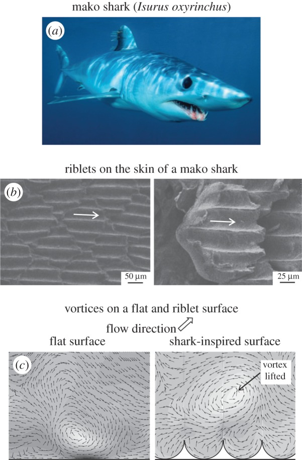
Low-drag surfaces have been inspired by mako shark skin due to riblet structures that lift vortices. (a) The skin of mako sharks (Isurus oxyrinchus) contains microscopic grooves aligned parallel to fluid flow called riblets. (b) Riblets on the skin of a mako shark (adapted from [15]) shown at two magnifications. (c) Vortices generated in turbulent flow shown on a flat and on a shark-inspired riblet surface (adapted from [25]). On the flat surface, a vortex is near the surface and generates drag. With the riblet surface, a vortex is lifted away from the surface, reducing drag and creating an overall drag reduction.
Riblet structures have also been found on the beaks of skimmer birds (Rynchops). There are three species of the Rynchopidae family: Rynchops niger (black skimmer), found in North and South America; Rynchops flavirostris (yellow skimmer), found in Africa; and Rynchops albicollis (white skimmer), found in India and Southeast Asia [26–31]. Figure 2a shows a photograph of a black skimmer. Adult black skimmers are approximately 400–500 mm in length with a 350–390 mm wingspan and weigh between 0.26 and 0.37 kg [32]. Using their long beaks with length of the order of 100 mm, these birds feed on small fish and crustaceans by catching them in flight. Skimmers are the only bird out of some 10 600 species to fly just above the water surface to fish for food. They have been recorded flying at speeds of 9–11 m s−1 when feeding [26,33].
Figure 2.
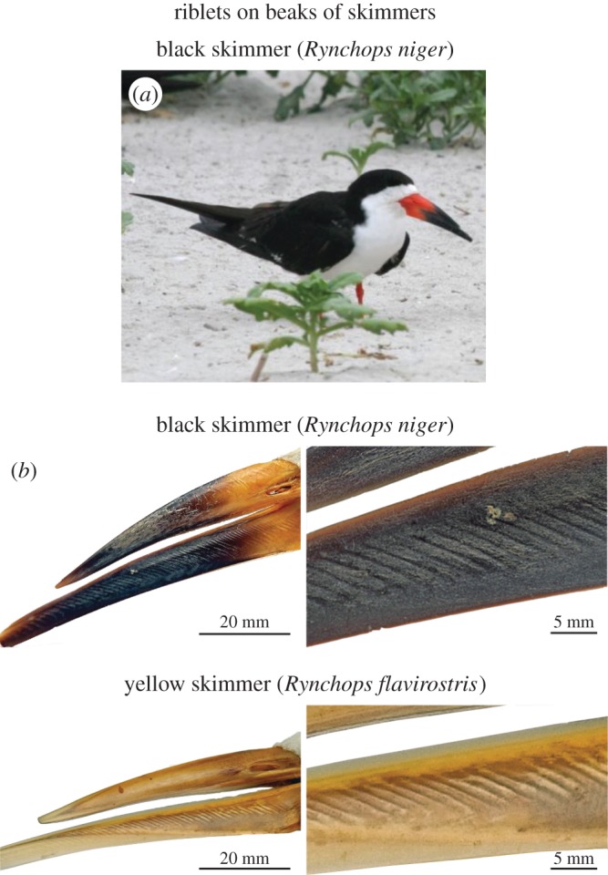
(a) Black skimmers (Rynchops niger) have riblet structures on their lower beaks. (b) Riblets on the beak of a black and yellow skimmer shown at two magnifications (courtesy of Prof. Wilhelm Barthlott, NEES Institute for Biodiversity of Plants). These riblets suggest low-drag surface properties.
Figure 2b shows the beaks and riblet structures on a black and yellow skimmer at two magnifications. The lower beak is 20–30 mm longer than the upper beak. Only the lower beak has riblets. At the tip of the lower beak, no riblets are present. For the rest of the beak, the riblets are generally spaced 2 mm apart and are 0.15 mm high. Additional surface characterization of the skimmer beak and riblet surfaces can be found in table 1. For comparison, mako shark skin characterization is also presented in table 1 [15].
Table 1.
Characterization of skimmer and mako surface structures.
| sample | description | surface | length | width | thickness |
|---|---|---|---|---|---|
| black and yellow skimmer beaks | parallel riblets at approximately 45° to flow on lower beak | lower beak | 80–100 mm | 5–15 mm | 0.5–3.3 mmb |
| riblets | 2–10 mm | 1.5–2 mm | 0–0.15 mm | ||
| mako skina | overlapping dermal denticles with around five scalloped riblets on each denticle | dermal denticles | 135–150 μm | 150–175 μm | 75–100 μm |
| riblets | 100–150 μm | 30–50 μm | 10–15 μm |
The skimmer gets its name from its unique feeding position, known as skimming, where the bird glides very close to the surface of the water with its lower beak submerged [26–28,34,35]. In this paper, we demonstrate that riblets found on the lower beak of skimmers help to reduce drag while in water. A low-drag surface on the beak would help reduce the time to capture prey, which results in an advantage in feeding. Two skimming postures are presented in figure 3; water flows either at an angle to the riblets or along the riblets. Water is more likely to flow at an angle to the riblets when the bird is either opening or closing its jaw, and water is more likely to flow along the riblets when the beak is fully extended.
Figure 3.
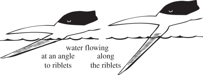
Two possible postures for skimmers when feeding. Water flows over the riblets at an angle of the order of 45° when the beak is opening or closing. Water flows aligned with the riblets at an angle of the order of 0° when the beak is fully opened.
We report the first study of skimmer beaks for low drag and their mechanism for drag reduction. Replicas of a black and yellow skimmer beak were studied for drag reduction in closed-channel, turbulent water flow, and then compared with mako shark skin. Two configurations of the riblet structures were studied to explore the differences between a partially opened beak and a fully opened beak. In addition, modelling of each configuration was carried out to understand the mechanisms of drag reduction. The experimental and computational data are compared, and a schematic of the drag mechanism is presented.
2. Experimental and computational procedure
In this section, first the sample fabrication process for creating two configurations of skimmer samples is described. Next, the experimental set-up for measuring the pressure drop is presented. Finally, the computational procedure for understanding the mechanism is explained.
(a). Fabrication process
Beak replicas of a black skimmer and a yellow skimmer were obtained through Prof. Wilhelm Barthlott at the NEES Institute for Biodiversity of Plants, Bonn, Germany. The birds came from the famous collection of Alexander Koenig, a German naturalist and zoologist. He acquired the yellow skimmer in 1899 and the black skimmer in 1903. Beak replicas were created using a two-step soft lithography technique. First, negative replicas were created for the lower beaks using a silicone impression material (Troll Factory), shown in figure 4. Next, positive replicas were created by pouring epoxy resin into the negative moulds.
Figure 4.
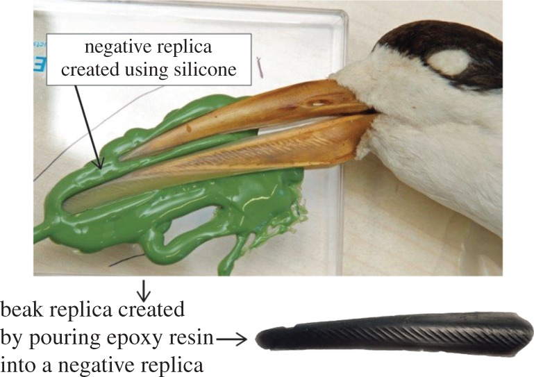
Moulding procedure to create a beak replica. First, silicone impression material is applied to the lower beak to create a negative replica. Epoxy resin is poured into the negative mould to create the beak replica.
The beak replicas were used to create a riblet surface for pressure drop measurements in a flow cell. The replica moulding procedure to create flow channel samples is shown in figure 5. Two configurations were created: a 45° surface, where the riblets are angled approximately 45° to the flow, and a 0° surface, where the riblets are approximately aligned with the flow. These two configurations were created in order to study the differences in beak position shown in figure 3.
Figure 5.

Two replica moulding procedures to create rectangular samples containing 45° or 0° skimmer surfaces. First, impression material is applied to the lower beak to create a negative replica. Next, liquid urethane polymer is poured into the impression material mould to create a positive replica. Finally, multiple urethane replicas are combined to create a longer riblet surface for testing in the flow cell. In the 0° skimmer sample, trimming and rotating of the urethane moulds is performed to align riblets in the direction of flow.
In order to create a flow channel sample, first a hydrophilic vinyl polysiloxane impression material (Take 1r; Kerr) was applied to a skimmer lower beak replica to create a negative sample. The impression material was chosen because of its ease of moulding and demoulding, and replication of riblet features. The impression material was applied directly to a lower beak replica using a cartridge dispensing gun with an attached mixing nozzle. A flat plate was pressed on top of the impression material and then cured at room temperature for 30 min.
Next, liquid urethane polymer (Smooth-Cast 305; Smooth-On) was poured into the negative impression replica to create a positive urethane replica. This polymer was chosen because of its ease of casting and demoulding from the impression material. After pouring the polymer, the urethane sample was cured at room temperature for 30 min, resulting in precise positive replicas. Multiple positive urethane replicas were combined in order to create a flow channel sample to fit in the flow cell. The 0° skimmer sample required additional processing in the form of trimming and rotating in order to align riblets in the direction of flow. To create a flat surface, a similar process was followed, except the liquid polymer was cast on a flat surface. A mako surface was obtained from previous experiments [36].
(b). Experimental set-up
The pressure drop for the samples in turbulent water flow was measured using the experimental apparatus shown in figure 6. A top and bottom surface were combined to create a rectangular closed channel 101 mm in length. The top surface had a milled channel with a height and width of 0.7 mm and 3.2 mm, respectively. The bottom surface was either a riblet surface for drag measurements or a flat surface for baseline measurements. These two surfaces were aligned, sealed with gaskets and clamped into the flow channel. Water was pumped from a tank to an elevated container, and the water velocity through the flow channel was modified by changing the height of the elevated container. An overflow line was connected to the elevated container to maintain a constant water height, and, therefore, constant flow rate. Water temperature was monitored with a digital thermometer and held at a temperature of 18.5±0.5°C for constant density (ρ=999 kg m−3) and kinematic viscosity (ν=1.04×10⁻⁶ m2 s−1) [37].
Figure 6.
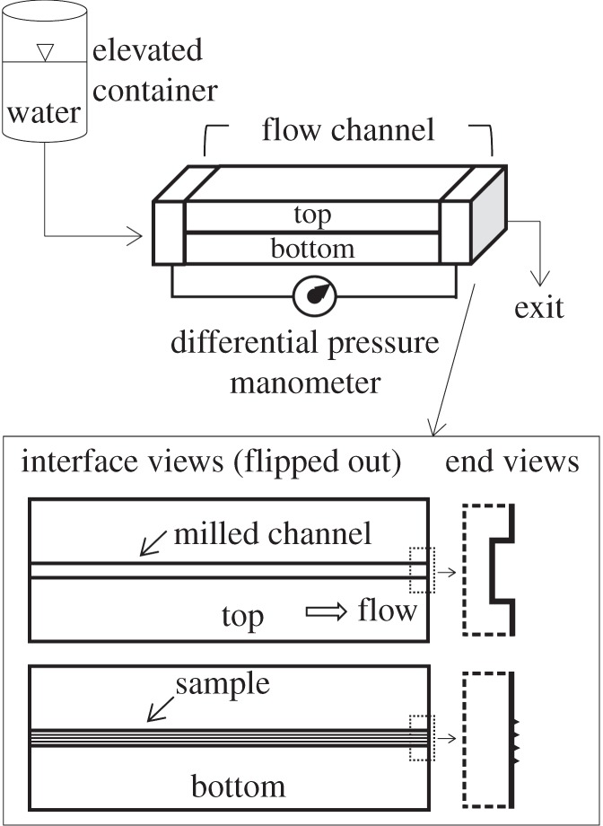
Experimental apparatus to measure drag in a closed-channel water configuration. Drag is measured via pressure drop from a differential pressure manometer across a flow channel. The flow channel is a split rectangular design composed of a milled channel and a sample surface. Flow rate through the channel is regulated with an elevated container containing water.
An Omega PX26-005DV differential pressure manometer was connected to the inlet and outlet of the flow channel and covered in room temperature vulcanized silicone for water repellency during testing. Data collection was performed at 300 Hz for 30 s with a laboratory amplifier (Vishay 2311) and a data acquisition card (USB-1208LS; Measurement Computing). Prior to testing, the system was calibrated using a pneumatic pressure system (RK-1600W6; Ametek).
In order to compare experimental pressure drop with theoretical calculations, the pressure drop (Δp) was found using the Darcy–Weisbach formula [38]. This equation calculates the pressure drop between two points at a distance L apart in an incompressible, closed-channel, fully developed flow using the average flow velocity (V),
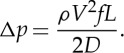 |
2.1 |
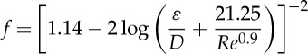
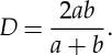
The friction factor (f) for turbulent flow was calculated with a roughness parameter (ε=5.8 μm) chosen for a typical pipe roughness with a milling procedure. The hydraulic diameter (D) was calculated with channel height (a) and channel width (b) [38],
 |
2.2 |
and
 |
2.3 |
The flow rate through the channel was used to determine the average velocity and Reynolds number (Re) [38],
| 2.4 |
(c). Computational procedure
To simulate flow over riblets, the computational fluid dynamic (CFD) software package ANSYS Fluent v.16.0 was used. This package uses the finite-volume method to solve the governing equations, which include the momentum Navier–Stokes and pressure-based continuity equations. This commercially available package contains various turbulence models employed in many studies. The package can implement parallel processing, and includes solver improvements, such as solving the momentum and continuity equations in a coupled manner [39].
In order to balance computational expense and accuracy, the large-eddy simulation (LES) model was chosen as the turbulence model. Because LES filters out the small flow-field scales and resolves the large flow-field scales using a subgrid scale (SGS), the computational expense is decreased. This filtering affects the results, but the small scales have less of an effect on the transport of mass and energy than the large scales. The large scales play a greater role in riblet drag. Thus, the mesh resolution and time step were chosen to resolve the large scales. In this work, the Wale SGS, designed to return the correct wall behaviour for wall-bounded flows, was chosen [39].
The closed-channel, computational domain of the skimmer geometry is shown in figure 7a, where the x-, y- and z-axes denote the streamwise, wall-normal and spanwise directions, respectively. The skimmer-inspired riblet surface is the bottom wall, shown in figure 7b. The flat surface is the top wall, and both the top and bottom surfaces are prescribed with no-slip boundary conditions. The inlet and outlet surfaces and the left and right surfaces were prescribed with periodic boundary conditions to eliminate wall effects. The model height, width and length are H=10 mm, W=8.485 mm and L=11.31 mm, respectively. The width and length had these values in order to have matching inlet and outlet surfaces and left and right surfaces to create a periodic domain. The computational domain was increased from the experimental set-up in order to increase the number of riblets in the spanwise direction and to better understand the mechanism.
Figure 7.
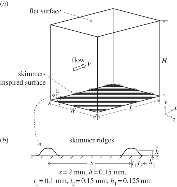
(a) Computational domain of the skimmer geometry. The flat surface is the top wall, and the skimmer-inspired surface is the bottom wall shown with the 45° configuration. (b) Magnification of the inspired surface to show dimensions for creating riblets. The perpendicular distance between riblets in the 0° and 45° cases was 2 mm.
In the streamwise direction, a constant instantaneous volume flux boundary condition was applied
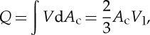 |
2.5 |
where Ac=HW is the cross-sectional area, V is the average velocity in the streamwise direction and V l is the centreline velocity of a laminar profile with the same volume flux. In equation (2.5), V l is two-thirds of V because of the difference between the average and maximum velocity in closed-channel flows [37]. The Reynolds number was 4200, chosen for turbulent flow and calculated using equation (2.4) where D=H/2, used with periodic boundary conditions.
The solution was initialized with a laminar velocity profile with turbulence fluctuations added afterwards. The simulation was advanced until natural turbulence was developed by monitoring wall shear stresses for quasi-periodic behaviour. Next, the simulation proceeded for additional time-to-time average drag results. The simulation had a computational time step of ΔTV l/D=0.025, where ΔT is the dimensional time step. The time-averaging period was at least 40 000 time steps.
Two skimmer-inspired riblet configurations were modelled. The first configuration is shown in figure 7a, with riblets at an angle of 45° to the flow. The second configuration had riblets at an angle of 0° aligned with the flow. The riblet dimensions were chosen based on a skimmer beak with riblet spacing of s=2 mm and height of h=0.15 mm. Riblet dimensions are commonly non-dimensionalized in order to compare their geometry using
| 2.6 |
and
 |
2.7 |
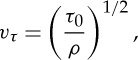
where the spacing s is the dimensional distance between riblets; vτ is the wall shear stress velocity, derived from kinetic energy through  ; and τ0 is the wall shear stress. Non-dimensionalized parameters are denoted with a superscript + [6,40]. Similarly, riblet height can be non-dimensionalized using [15]
| 2.8 |
The dimensions of the computational domain were chosen to be large enough to include the expected scales of flow structures, such as vortices, and to be greater than the minimal flow unit. The minimal flow unit is the minimum size of a computational domain in order to model turbulent flow accurately, and has dimensions of x+≈300 and z+≈100 [41]. These dimensions were non-dimensionalized in a manner similar to equation (2.6). For this model, the dimensions were x+≈410 and z+≈310.
For the 45° skimmer configuration, an unstructured tetrahedral mesh was used in order to mesh the riblets accurately. In the wall-normal direction, 200 nodes were used with the first node located at y+≈0.12 on the flat surface. In the spanwise direction, the average node spacing was z+≈1.5. In the streamwise direction, 200 nodes were used for an average x+≈2. Using these inputs, the model had approximately 3 million tetrahedral cells.
For the 0° skimmer configuration, a swept mesh with a node spacing of x+≈25 using 16 equally spaced nodes was used. It was possible to use this mesh because the cross-sectional area did not change, as opposed to the 45° configuration. In the spanwise direction, the average node spacing was z+≈1.8. In the wall-normal direction, 250 nodes were used with the first node located at y+≈0.1 on the flat surface. Using these inputs, the model had roughly 1 million hexahedral cells.
For all models, the mesh was biased towards the riblet and flat surfaces in order to keep the first grid point at y+<1, as required by the LES model, and to resolve the flow near the walls more accurately. The grid resolution was approximately the same on the riblet and flat surfaces for drag comparison purposes, and was finer than the recommended requirements of x+=40 and z+=20 suggested by the software user guide [39].
To validate the model, turbulent flow around a square cylinder was performed and compared with computational and experimental results. The results agreed, and the model was validated for use in modelling riblet structures [23]. In addition, to validate the simulations, the non-dimensional mean streamwise velocity profile over a flat surface was compared with Spalding's law of the wall, which states that the average velocity at a point in turbulent flow is logarithmically proportional to the distance between that point and the wall [42]. The law of the wall and the LES simulation were in good agreement, which validated the simulation [24].
3. Results and discussion
In this section, first the experimental results for pressure drop measurements with the flow channel are presented. Then, the computational results to explain the mechanism are presented.
(a). Experimental results
In order to measure pressure drop, each sample was placed into the flow cell and tested at velocities ranging from 2 to 5 m s−1, corresponding to turbulent Reynolds numbers ranging from 2100 to 5700. The pressure drop results are presented in figure 8, comparing the 0° and 45° black skimmer and the 0° and 45° yellow skimmer. In addition, mako pressure drop data are presented for comparison. The pressure drop for the predicted flat (using equation (2.1)) and experimental flat data are also shown. The percentage pressure drop for the skimmer and mako samples is calculated using the predicted flat as the reference.
Figure 8.

Pressure drop of samples for turbulent water flow. For comparison, the predicted pressure drop for a flat surface and experimental measurements for a flat, milled surface are shown. This line is used as a reference for percentage pressure drop. Samples include 0° and 45° riblet configurations for both the black skimmer and yellow skimmer and the mako shark skin. Higher pressure drop translates to higher drag; therefore, pressure drops less than the flat surface indicate drag reductions.
The samples were tested in the turbulent regime, because it was expected that riblets would not provide a drag reduction in laminar flow, similar to shark-inspired riblets [21,43]. This principle is shown in figure 8. As the curves approach the laminar–turbulent transition at Re =2100, they more closely approximate the flat sample curve.
All four skimmer samples and the mako sample have a pressure drop that is less than the flat sample, which denotes a drag reduction. The mako sample had the greatest drag reduction, followed by the 45° skimmer samples, and then the 0° skimmer samples. Because the black and yellow skimmer beaks have similar riblet structures, there was not a significant difference between their pressure drop curves with the same configuration. Because the skimmer configuration was more important than the species, the curve fit for each configuration will be used to show results and will be referenced as black or yellow skimmer data. In general, the pressure drop percentage increased as Reynolds number increased. At a Reynolds number of 5500, the pressure drop percentages, calculated using the curve fit, were approximately 6%, 12% and 19% for the 0° skimmer, 45° skimmer and mako samples, respectively.
From these results, we thought that 45° riblets give a drag reduction benefit over 0° riblets due to the geometry of vortices. Typical vortex dimensions have diameter d+=30–40 [24,44–47] and length ℓ+=100–200 [24,48,49]. Because a vortex has a length around five times longer than the diameter, it is more likely to be lifted from the riblet surface when the riblets are angled. With angled riblets, a vortex could sit on top of multiple riblets. However, in aligned riblets such as the 0° configuration, the vortex diameter becomes a more important parameter. Because the diameter is smaller than the length, the vortex could now fall down into the riblet spacing. The mako shark could give much greater drag reductions because, with smaller riblet spacing, vortices could be lifted on both the diameter and length parameters.
In order to further explore the mechanism, a computational study was performed. Owing to the flow cell geometry, vortices were unable to be viewed. However, using a simulation the interaction between vortex structures and a riblet surface could be viewed.
(b). Computational results
The 0° and 45° skimmer configurations were modelled in order to understand the drag reduction mechanism. After completing the simulation, the time-averaged percentage drag change was calculated. The percentage drag reduction was 2.8% and 3.9% for the 0° and 45° skimmers, respectively. The mako drag reduction taken from the shark-inspired surface from Martin & Bhushan [25] showed a drag reduction of 4.5%. The computational drag reduction and experimental pressure drop percentages are shown in table 2. The experimental pressure drops have greater percentages than the computational drag reduction. One explanation is that periodic boundary conditions were used, which removed wall effects from the simulation. In the experimental study, the walls helped lift vortices in the corners between the riblet surface and the side walls, which could decrease drag.
Table 2.
Measured pressure drop and calculated drag reduction at Re ≈4200.
| surface | measured pressure drop (%) | calculated drag reduction (%) |
|---|---|---|
| 0° skimmer | 5 | 2.8 |
| 45° skimmer | 9 | 3.9 |
| mako | 18 | 4.5a |
aData from Martin & Bhushan [25].
By comparing vortex images on the y–z planes of the simulations, vortex locations could be compared. Figure 9 shows typical vortices on a flat and 0° skimmer surface with the flow into the image through velocity vectors and vorticity. Figure 9a shows a vortex on the flat surface that creates high shear stress and drag. By lifting these vortices from the surface, drag reductions can be obtained. Figure 9b shows various images of vortices on the 0° skimmer surface. The riblet spacing of s+=73 is larger than the typical vortex diameter of d+=30–40. With a vortex diameter smaller than the spacing, some vortices fall down into riblet valleys. However, some vortices were also lifted from the surface and rested on the tips of the riblets. Because the riblets do not protrude very far into the flow (h+=5.5), the vortices are less affected by the higher velocity flow away from the surface. This situation allows for some vortices to rest on top of the riblets. In addition, because the riblets are not very high, the surface area does not drastically increase, adding significant drag. These two factors helped lead to a drag reduction for the 0° skimmer configuration.
Figure 9.
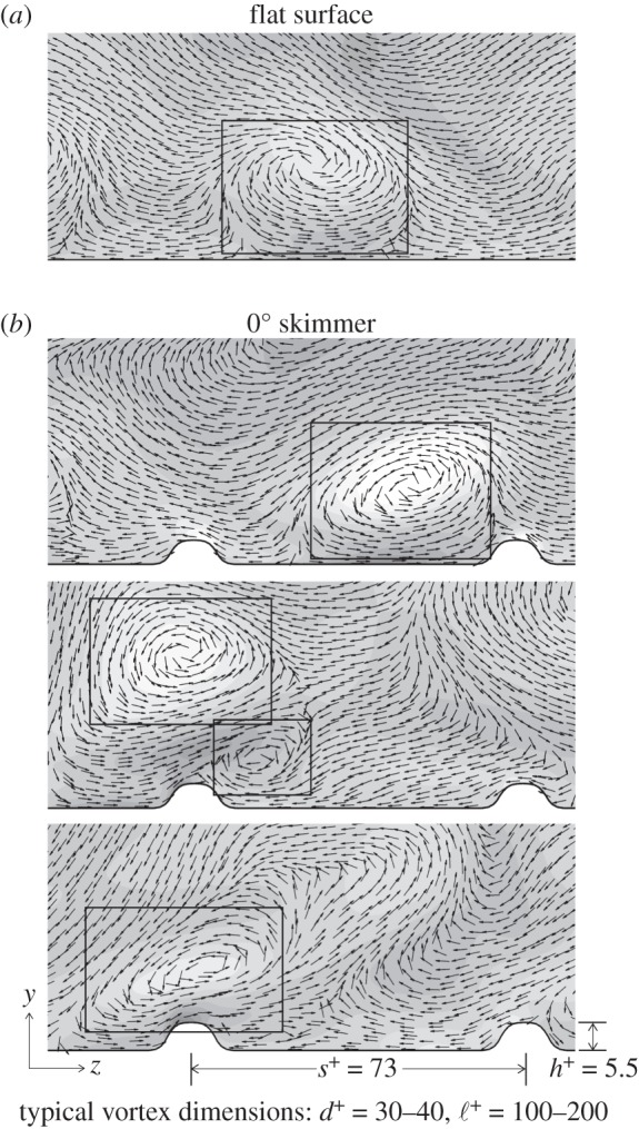
Vortex images for the flat surface and 0° skimmer surface. (a) On a flat surface, vortices are located close to the surface and are associated with high drag. Typical vortex dimensions include diameter d+=30–40 and length ℓ+=100–200. (b) On the 0° skimmer surface, riblets had a non-dimensional spacing s+=73 and height h+=5.5. Riblets can help lift vortices from the surface, decreasing drag; however, because vortices have diameter smaller than the spacing, vortices can also fall into riblet valleys.
In order to understand the drag reduction mechanism with the 45° skimmer configuration, an isometric image of the riblet surface is shown in figure 10a. The image shows two y–z planes at two different locations on the surface. In these planes, a vortex is shown being lifted by riblets and not falling into the gap in between. The detail images (figure 10b) show velocity vectors and vorticity on these planes. The distance between the riblets in the flow direction is 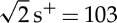 , which is on the lower range for vortex length. Because vortices are generally longer than the riblet gap, they are lifted from the surface, creating a drag reduction. Riblets do not need to lift a vortex at all points along its length, but only at some points along its length in order to generate a drag reduction. Because vortices are lifted on their length parameter, the 45° skimmer configuration has larger drag reduction results than the 0° skimmer configuration. Riblets at a 90° configuration or perpendicular to the direction of flow were not explored, because skimmers do not have this riblet orientation. It is expected that a 90° configuration would result in a drag increase due to the increase in pressure drag.
Figure 10.
(a) Vortex images for the 45° skimmer surface at two locations on the riblet surface. (b) Detail images show a vortex lifted away from the surface. Because vortices have a length around five times longer than their diameter, angling the riblets allows for vortices to sit on top of the riblets and not fall into a riblet gap. When riblets are aligned with the flow, vortices can fall into riblet valleys because the vortex diameter is smaller than the riblet spacing.
4. Conclusion
Researchers are looking for methods to reduce drag for applications in transportation and industrial fields. Nature has provided inspiration for drag-reducing surfaces. Shark-inspired geometries have been shown to reduce drag through riblets, microscopic grooves aligned parallel to fluid flow. Riblets with spacing smaller than the vortex diameter can lift vortices, which are responsible for large shear stresses and drag. In this work, the riblet structures found on the beaks of black and yellow skimmers were studied experimentally and computationally for drag reductions in 0° and 45° configurations. Using a differential pressure manometer, drag on skimmer replica surfaces was measured and compared with a flat surface and a mako surface. Using computational modelling, the mechanism of drag reduction for skimmer-inspired riblets was explored for both configurations.
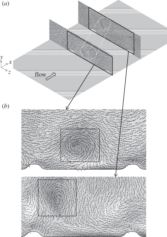
The skimmer surfaces showed pressure drop reductions of 6% and 12% at a turbulent Reynolds number of 5500 for the 0° and 45° configurations, respectively. A greater pressure drop reduction of 19% was obtained using the mako shark, probably due to the smaller spacing between riblets. A smaller riblet spacing means more vortices are able to be lifted from the surface. Through computational modelling of the configurations, the mechanism of drag reduction was explored. In the 0° configuration, with a riblet spacing larger than the vortex diameter, vortices were able to fall down into riblet valleys. However, some vortices were lifted from the surface due to a riblet height that allowed for vortices to rest on top of a riblet. With at least some vortices being lifted, a drag reduction resulted. In the 45° configuration, vortices were lifted on subsequent riblets and did not fall into the gaps, because a vortex has a length longer than the riblet gap. This mechanism of lifting vortices in the 45° configuration is shown schematically in figure 11. This 45° configuration resulted in greater drag reductions than the 0° configuration.
Figure 11.
Schematic shows that skimmers may have 45° riblets for low-drag properties. Angled riblets are more likely to lift vortices, whereas aligned riblets are more likely to have vortices that fall into riblet valleys. Lifting vortices from a surface leads to low drag.
Riblet structures found on black and yellow skimmer beaks have been shown for the first time to provide drag reduction. Reducing drag in skimmers may help these birds catch small fish and crustaceans when feeding. Similar riblet structures could be applied to reducing drag in other applications, such as transportation and other industries.
Acknowledgements
Many thanks to Prof. Wilhelm Barthlott at the NEES Institute for Biodiversity of Plants, University of Bonn, Germany, for providing skimmer replicas and scientific insight.
Competing interests
We declare we have no competing interests.
Funding
This work was supported in part by an allocation of computing time from the Ohio Supercomputer Center.
References
- 1.Bhushan B. 2009. Biomimetics: lessons from nature—an overview. Phil. Trans. R. Soc. A 367, 1445–1486. ( 10.1098/rsta.2009.0011) [DOI] [PubMed] [Google Scholar]
- 2.Bhushan B. 2016. Biomimetics: bioinspired hierarchical-structured surfaces for green science and technology, 2nd edn Heidelberg, Germany: Springer. [Google Scholar]
- 3.Davies M. (ed.). 2002. Standard handbook for aeronautical and astronautical engineers. New York, NY: McGraw-Hill. [Google Scholar]
- 4.Brostow W. 2008. Drag reduction in flow: review of applications, mechanism and prediction. J. Indust. Eng. Chem. 14, 409–416. ( 10.1016/j.jiec.2008.07.001) [DOI] [Google Scholar]
- 5.Walsh MJ, Anders JB Jr.. 1989. Riblet/LEBU research at NASA Langley. Appl. Sci. Res. 46, 255–262. ( 10.1007/BF00404822) [DOI] [Google Scholar]
- 6.Bechert DW, Bruse M, Hage W, van der Hoeven JGT, Hoppe G. 1997. Experiments on drag reducing surfaces and their optimization with an adjustable geometry. J. Fluid Mech. 338, 59–87. ( 10.1017/S0022112096004673) [DOI] [Google Scholar]
- 7.Burger ED, Munk WR, Wahl HA. 1982. Flow increase in the Trans Alaska Pipeline through use of a polymeric drag-reducing additive. J. Petrol. Technol. 34, 377–386. ( 10.2118/9419-PA) [DOI] [Google Scholar]
- 8.Kennedy JL. 1993. Oil and gas pipeline fundamentals. Tulsa, OK: PennWell Books. [Google Scholar]
- 9.Deyuan Z, Yuehao L, Huawei C, Xinggang J. 2011. Exploring drag-reducing grooved internal coating for gas pipelines. Pipeline Gas J. 238, 59. [Google Scholar]
- 10.Reif W. 1985. Squamation and ecology of sharks. Cour. Forsch.-Inst. Senckenberg 78, 1–255. [Google Scholar]
- 11.Bechert DW, Bruse M, Hage W. 2000. Experiments with three-dimensional riblets as an idealized model of shark skin. Exp. Fluids 28, 403–412. ( 10.1007/s003480050400) [DOI] [Google Scholar]
- 12.Jung YC, Bhushan B. 2010. Biomimetic structures for fluid drag reduction in laminar and turbulent flows. J. Phys.: Condens. Matter 22, 1–9. ( 10.1088/0953-8984/22/3/035104) [DOI] [PubMed] [Google Scholar]
- 13.Dean B, Bhushan B. 2010. Shark-skin surfaces for fluid-drag reduction in turbulent flow: a review. Phil. Trans. R. Soc. A 368, 4775–4806. ( 10.1098/rsta.2010.0201) [DOI] [PubMed] [Google Scholar]
- 14.Oeffner J, Lauder GV. 2012. The hydrodynamic function of shark skin and two biomimetic applications. J. Exp. Biol. 215, 785–795. ( 10.1242/jeb.063040) [DOI] [PubMed] [Google Scholar]
- 15.Bixler GD, Bhushan B. 2013. Fluid drag reduction with shark-skin riblet inspired microstructured surfaces. Adv. Funct. Mater. 23, 4507–4528. ( 10.1002/adfm.201203683) [DOI] [Google Scholar]
- 16.Bixler GD, Bhushan B. 2013. Shark skin inspired low-drag microstructured surfaces in closed channel flow. J. Colloid Interface Sci. 393, 384–396. ( 10.1016/j.jcis.2012.10.061) [DOI] [PubMed] [Google Scholar]
- 17.Lang AW, Bradshaw MT, Smith JA, Wheelus JN, Motta PJ, Habegger ML, Hueter RE. 2014. Movable shark scales act as a passive dynamic micro-roughness to control flow separation. Bioinspir. Biomim. 9, 036017 ( 10.1088/1748-3182/9/3/036017) [DOI] [PubMed] [Google Scholar]
- 18.Wen L, Weaver JC, Thornycroft PJ, Lauder GV. 2015. Hydrodynamic function of biomimetic shark skin: effect of denticle pattern and spacing. Bioinspir. Biomim. 10, 066010 ( 10.1088/1748-3190/10/6/066010) [DOI] [PubMed] [Google Scholar]
- 19.Díez G, Soto M, Blanco JM. 2015. Biological characterization of the skin of shortfin mako shark Isurus oxyrinchus and preliminary study of the hydrodynamic behaviour through computational fluid dynamics. J. Fish. Biol. 87, 123–137. ( 10.1111/jfb.12705) [DOI] [PubMed] [Google Scholar]
- 20.Choi H, Moin P, Kim J. 1993. Direct numerical simulation of turbulent flow over riblets. J. Fluid Mech. 255, 503–539. ( 10.1017/S0022112093002575) [DOI] [Google Scholar]
- 21.Goldstein D, Handler R, Sirovich L. 1995. Direct numerical simulation of turbulent flow over a modelled riblet-covered surface. J. Fluid Mech. 302, 333–376. ( 10.1017/S0022112095004125) [DOI] [Google Scholar]
- 22.Lee SJ, Lee SH. 2001. Flow field analysis of a turbulent boundary layer over a riblet surface. Exp. Fluids 30, 153–166. ( 10.1007/s003480000150) [DOI] [Google Scholar]
- 23.Martin S, Bhushan B. 2014. Fluid flow analysis of a shark-inspired microstructure. J. Fluid Mech. 756, 5–29. ( 10.1017/jfm.2014.447) [DOI] [Google Scholar]
- 24.Martin S, Bhushan B. 2016. Fluid flow analysis of continuous and segmented riblet structures. RSC Adv. 6, 10 962–10 978. ( 10.1039/C5RA20944G) [DOI] [Google Scholar]
- 25.Martin S, Bhushan B. 2016. Modeling and optimization of shark-inspired riblet geometries for low drag applications. J. Colloid Interface Sci. 474, 206–215. ( 10.1016/j.jcis.2016.04.019) [DOI] [PubMed] [Google Scholar]
- 26.Zusi RL. 1962. Structural adaptations of the head and neck in the black skimmer: Rynchops nigra. Nuttall Orn. Club 3, 1–101. [Google Scholar]
- 27.Zusi RL. 1996. Family Rynchopidae (skimmers). Handb. Birds World 3, 668–677. [Google Scholar]
- 28.Withers PC, Timko PL. 1977. The significance of ground effect to the aerodynamic cost of flight and energetics of the black skimmer (Rhyncops nigra). J. Exp. Biol. 70, 13–26. [Google Scholar]
- 29.Burger J, Gochfeld M. 1990. The black skimmer: social dynamics of a colonial species. New York, NY: Columbia University Press. [Google Scholar]
- 30.Martin GR, McNeil R, Rojas L. 2007. Vision and the foraging technique of skimmers (Rynchopidae). Ibis 149, 750–757. ( 10.1111/j.1474-919X.2007.00706.x) [DOI] [Google Scholar]
- 31.Smith JC. 2015. Black skimmer (Rynchops niger) conservation management plan. Long Island City, NY: New York State Department of Environmental Conservation. [Google Scholar]
- 32.Gochfeld M, Burger J. 1994. Black skimmer (Rynchops niger). In The birds of North America, vol. 108 (eds A Poole, F Gill), pp. 1–28 Philadelphia, PA: The Academy of Natural Sciences. [Google Scholar]
- 33.Schnell GD, Hellack JJ. 1979. Bird flight speeds in nature: optimized or a compromise? Am. Nat. 113, 53–66. ( 10.1086/283364) [DOI] [Google Scholar]
- 34.Blake RW. 1983. Mechanics of gliding in birds with special reference to the influence of the ground effect. J. Biomech. 16, 649–654. ( 10.1016/0021-9290(83)90115-X) [DOI] [PubMed] [Google Scholar]
- 35.Rojas LM, McNeil R, Cabana T, Lachapelle P. 1997. Diurnal and nocturnal visual function in two tactile foraging waterbirds: the American white ibis and the black skimmer. Condor 99, 191–200. ( 10.2307/1370237) [DOI] [Google Scholar]
- 36.Bixler GD, Bhushan B. 2013. Bioinspired micro/nanostructured surfaces for oil drag reduction in closed channel flow. Soft Matter 9, 1620–1635. ( 10.1039/C2SM27070F) [DOI] [Google Scholar]
- 37.Munson BR, Okiishi TH, Huebsch WW, Rothmayer AP. 2012. Fundamentals of fluid mechanics, 7th edn Hoboken, NJ: Wiley. [Google Scholar]
- 38.Blevins RD. 1984. Applied fluid dynamics handbook. New York, NY: Van Nostrand Reinhold. [Google Scholar]
- 39.Anonymous. 2016. ANSYSr Fluent, Release 16.0, Help System, Fluent User's Guide, ANSYS, Inc., Canonsburg, PA.
- 40.Walsh MJ. 1982. Turbulent boundary layer drag reduction using riblets. In Proc. AIAA 20th Aerospace Sciences Meeting, Orlando, FL, 11–14 January 1982, paper no. AIAA-82-0169. Reston, VA: American Institute of Aeronautics and Astronautics.
- 41.Jimenez J, Moin P. 1991. The minimal flow unit in near-wall turbulence. J. Fluid Mech. 225, 213–240. ( 10.1017/S0022112091002033) [DOI] [Google Scholar]
- 42.Spalding DB. 1961. A single formula for the law of the wall. Trans. ASME J. Appl. Mech. 28, 455–458. ( 10.1115/1.3641728) [DOI] [Google Scholar]
- 43.Mohammadi A, Floryan J. 2013. Groove optimization for drag reduction. Phys. Fluids 25, 113601 ( 10.1063/1.4826983) [DOI] [Google Scholar]
- 44.Kim H, Kline SJ, Reynolds WC. 1971. The production of turbulence near a smooth wall in a turbulent boundary layer. J. Fluid Mech. 50, 133–160. ( 10.1017/S0022112071002490) [DOI] [Google Scholar]
- 45.Kim J, Moin P, Moser R. 1987. Turbulence statistics in fully developed channel flow at low Reynolds number. J. Fluid Mech. 177, 133–166. ( 10.1017/S0022112087000892) [DOI] [Google Scholar]
- 46.Blackwelder RF, Eckelmann H. 1979. Streamwise vortices associated with the bursting phenomenon. J. Fluid Mech. 94, 577–594. ( 10.1017/S0022112079001191) [DOI] [Google Scholar]
- 47.Robinson SK. 1991. Coherent motions in the turbulent boundary layer. Annu. Rev. Fluid Mech. 23, 601–639. ( 10.1146/annurev.fl.23.010191.003125) [DOI] [Google Scholar]
- 48.Lyons SL, Hanratty TJ, McLaughlin JB. 1989. Turbulence-producing eddies in the viscous wall region. AIChE J. 35, 1962–1974. ( 10.1002/aic.690351207) [DOI] [Google Scholar]
- 49.Garcia-Mayoral R, Jimenez J. 2011. Hydrodynamic stability and breakdown of the viscous regime over riblets. J. Fluid Mech. 678, 317–347. ( 10.1017/jfm.2011.114) [DOI] [Google Scholar]