Abstract
Purpose
To present a constrained optimal-control (OC) framework for designing large-flip-angle parallel-transmit (pTx) pulses satisfying hardware peak-power as well as regulatory local and global specific-absorption-rate (SAR) limits. The application is 2D and 3D spatial-selective 90° and 180° pulses.
Theory and Methods
The OC gradient-ascent-pulse-engineering method with exact gradients and the limited-memory Broyden-Fletcher-Goldfarb-Shanno method is proposed. Local SAR is constrained by the virtual-observation-points method. Two numerical models facilitated the optimizations, a torso at 3 T and a head at 7 T, both in eight-channel pTx coils and acceleration-factors up to 4.
Results
The proposed approach yielded excellent flip-angle distributions. Enforcing the local-SAR constraint, as opposed to peak power alone, reduced the local SAR 7 and 5-fold with the 2D torso excitation and inversion pulse, respectively. The root-mean-square errors of the magnetization profiles increased less than 5% with the acceleration factor of 4.
Conclusion
A local and global SAR, and peak-power constrained OC large-flip-angle pTx pulse design was presented, and numerically validated for 2D and 3D spatial-selective 90° and 180° pulses at 3 T and 7 T.
Keywords: virtual observation points, local SAR, optimal control, multidimensional spatial-selective excitation, hard constraints
INTRODUCTION
MRI with parallel-transmit (pTx) (1,2) coils and pulses have been designed and used in recent years for accelerated 2D (3–5) and 3D (6) spatial-selective excitations, slice selective slice shimming using “spoke” pulses (4), water-selective imaging (7), nonselective excitations of uniform 3D volumes for 3D imaging (8,9), and simultaneous multislice imaging (10). It is known, however, that with pTx the subject in the scanner is potentially at risk of local hot-spots of temperature elevations due to the highly nonhomogeneous distribution of specific absorption rate (SAR). The SAR distribution depends on the geometry and electrical properties of the conductive tissues of the subject, the coil geometry, and the radiofrequency (RF) pulses.
For this reason, current patient safety guidelines include strict SAR limitations that must be enforced for every patient (11–13). Both global SAR (i.e., average of SAR over the whole part of the body exposed to the RF coil) and local SAR (i.e., SAR at a specific location in space, but averaged in a 10-g tissue volume) are regulated. The distribution of SAR in individual patients is best captured by 3D maps that contain hundreds of thousands of voxels. Each voxel is represented by a C × C matrix (C is the number of pTx coils) describing the local interaction between the electric fields created by the pTx coils (14). For pulse optimization, these SAR matrices can be incorporated as constraints to enforce the regulatory SAR limits (12,15,16). Doing so without compression of the set of SAR matrices in the body model would result in hundreds of thousands of SAR constraints, which is computationally too demanding for most algorithms and the time constraints of the pulse calculation.
Instead, Eichfelder and Gebhardt (14) have proposed a compression scheme called the virtual-observation-point (VOP), that clusters the SAR matrices such that it suffices to satisfy the SAR limitations for one matrix per cluster, i.e., the VOP matrix. The compression factor depends on a user-defined SAR overestimation tolerance (14,17), but exploiting VOPs dramatically reduces the number of SAR constraints. In relatively new usages of VOPs, Boulant et al. (18) showed a physiologically relevant Temperature-VOP algorithm for constraining temperature-rise rather than SAR, and Pendse and Rutt (19) simulated localized RF hyper-thermia using VOPs.
Many pulse designs use (magnitude) least-squares ((M)LS) optimizations (17,20–24). Recently, Hoyos-Idrobo et al. (25) made a comprehensive comparison on different strategies to solve MLS problems incorporating efficient local SAR and power constraints. They investigated kT-point (9,26) pulses in both the small-tip-angle (STA) and large-tip-angle (LTA) regimes, and used graphical-processing-units (GPUs) to faster simulate the Bloch equations facilitating the LTA MLS optimizations.
In this study, we propose optimal control (OC) (27) as another method to compute LTA pulses under local-SAR, global-SAR, and peak-power constraints for safe, multidimensional RF pulse designs.
For such a pulse-design, a rough distinction between OC and, say, (M)LS methods is that OC considers all the dynamical information of the magnetization vector during a given pulse, e.g., through a Bloch simulation. The (M)LS methods typically incorporate the dynamics into a system matrix and compare the resulting magnetization a given pulse yields with the target (or as in Hoyos-Idrobo et al. (25) for LTA pulses, use a Bloch simulation instead of the system matrix approach).
The LS problem is magnetization-phase selective, but the MLS problem, which is not, has shown advantages regarding flip-angle uniformity of spoke-pulses (28). Thus, to exploit the extended degrees of freedom with MLS and retrieving a specific magnetization phase certain actions need to be taken (17,25). The OC problems are typically formulated as magnetization phase-selective (29–31), but there are also other examples (30,32).
In the linear STA regime, the family of LS methods is very robust and fast for most applications because there are efficient ways to propagate, for example, by conjugate-gradient methods (33,34). When attempting to design LTA pulses, it is well known that STA pulse-design methods and even the linear-class LTA method (35) may produce nonideal pulses compared with, e.g., pulses derived using the Bloch equation (5,25,32) or the Shinnar-Le Roux algorithm (36). OC excels when having hundreds to thousands of free parameters, e.g., the amplitude and phase of several millisecond-long pTx pulses and time-steps of the order of microseconds. Therefor OC is efficient for pulse-designs of advanced pulse-shapes, as opposed to optimization of the amplitude and phase of fixed shapes, e.g., spokes-pulses. Albeit presenting a wealth of interesting applications, previous OC MRI pulse-design methods have considered power regularization (5,32,31,37–43), but not strict local-SAR constraints. Despite pulse power is associated with SAR, average- and peak-power regularization or constraints alone cannot guarantee elimination of local hot-spots and local-SAR control needs to be enforced separately. Second to that, regularization of pulse power is usually performed by modification of the cost functional (5,31,32,37–43). However, the regularization level needs to be optimized as well, e.g., by the L-curve method, which is time consuming.
In this work, we incorporate strict peak-power, global SAR and VOP-based local-SAR control similar to Guérin et al. and Hoyos-Idrobo et al. (17,25) in an OC pulse-design strategy. This work is built upon our previous OC pulse designs described in Vinding et al. (31) and will be available at nmr.au.dk. Based on Bloch-equation evaluations, our software is general for designing multidimensional, pTx, and arbitrary flip-angle pulses. We demonstrate the principle with optimizations of 2D and 3D spiral-based spatial-selective RF pulses, with the individual hard constraints investigated separately.
THEORY
We follow the notation of Xu et al. (5) for the description of multidimensional pTx RF pulses that we design with our OC approach. In a given location r = [x, y, z]T, the time-dependent magnetization vector M(r, t) = [Mx(r, t), My(r, t), Mz(r, t)]T has a motion described by Bloch’s equations. The superscript T refers to a transposed vector or matrix. Ignoring relaxation effects, we have:
| [1] |
where the · signifies a time-derivative, and
| [2] |
The multidimensional capabilities adhere to the time-varying field gradient G(t) = [Gx(t), Gy(t), Gz(t)]T and the net, resonant RF-field components ωx(r, t) and ωy(r, t), which are superpositions of the field components from C separate pTx coils. The c’th coil has a complex transmit sensitivity . The complex RF pulse executed on this coil is noted uc(t) + ivc(t). Hence, the net RF-field components are given as (5):
| [3] |
and
| [4] |
In the given OC approach, the goal is to compute the optimal waveforms and achieving the target magnetization profiles within the shortest excitation time.
In this work, we consider the field gradient waveform G(t) fixed throughout the RF optimization. We use a decaying, oscillating waveform with a duration T that forms a spiral in the excitation k-space.
We discretize time (index n) and space (index p) such that there are N time steps of duration Δt, i.e., T = NΔt, and P locations. Hence, the magnetization vector will be recast as Mp,n understanding that there are N + 1 states for every spatial point because the n’th set of controls transfers Mp,n−1 to Mp,n. Other variables will adopt the same notation.
We choose to optimize the performance J-metric (projection of the final magnetization vector onto the target magnetization vector) defined as:
| [5] |
where normalization ensures that the optimal pulse solution is achieved when J = 1.
In this approach, we exclude the regularized RF power penalty term (5,31). Instead, we introduce hard constraints on local SAR (Llim) and global SAR (Glim):
| [6] |
| [7] |
where xn is the vertical concatenation of the complex RF waveforms executed on each pTx channel and expressed in Volt. Local-SAR constraints in Eq. [6] are computed by the VOPs (Vv) of index v (14,17). The global-SAR limit, Eq. [7], is imposed through a single global-SAR matrix, G(2). A peak-power constraint is enforced through a built-in capacity of the solver we use (in our case MATLAB’s nonlinear programming solver fmincon). The SAR constraints and their gradients with respect to the controls are supplied analytically by means of a script that fmincon makes calls to.
For OC procedure to address Eq. [5], we use the gradient-ascent-pulse-engineering (GRAPE) (44) algorithm with second-order derivative information using the limited-memory (45,46), Broyden (47), Fletcher (48), Goldfarb (49), Shanno (50) (L-BFGS) quasi-Newton method. The BFGS method is one method that overcomes the difficulty of expressing an analytical (inverse) Hessian matrix. Instead, the inverse Hessian matrix is estimated iteratively using only the knowledge of the first-order derivatives, i.e., the gradients. In memory-intensive problems, it may, furthermore, be beneficial to use the L-BFGS method that approximates and replaces the dense inverse Hessian matrix by a few vectors instead.
As shown by de Fouquieres et al. (51), this combined GRAPE-(L-)BFGS method provides faster convergence than GRAPE alone. However, (L-)BFGS requires exact gradient expressions as opposed to gradients precise to first order. Otherwise, approximation errors accumulate in the estimated Hessian matrix, which dramatically degrades convergence. Therefore, we replace the first-order gradient expression in the traditional implementation of GRAPE by an exact expression (51).
Following the procedure of Vinding et al. (31), an implicit gradient expression for the optimization problem in Eq. [5] is
| [8] |
and
| [9] |
where Lp,n is the Lagrange multiplier introduced to adjoin Eq. [5] with Eq. [1] through principles of calculus-of-variations. It is noted that the final state for the Lagrange multiplier in this two-point boundary-value problem (32) is equal to the target magnetization vector. The matrices and are derivative operators for the uc,n and vc,n controls, respectively. They can be derived analytically either by solving the left-hand side of Eqs. [8] and [9] or by following the approach of Floether et al. (52). The latter involves forming the following block matrix,
| [10] |
The left-hand side of Eq. [10] shows that the block matrix is composed of the Bloch dynamics matrix, Ωp,n, from Eq. [1] on the diagonal and in the upper right a control operation matrix, , given as
| [11] |
where and if j = u, and and if j = v. The matrix exponential of this block matrix multiplied by the time-step, Δt, yields another block matrix as shown on the right-hand side of Eq. [10]. Here, the diagonal matrices are, essentially, the rotation matrices that can also be retrieved from solving the Bloch equation, Eq. [1], for a known initial condition. That is (31),
| [12] |
with
| [13] |
But of interest, the upper right of the right-hand side of Eq. [10], , is an exact derivative operator with respect to the controls. Thus, numerically calculating the left-hand side of Eq. [10] readily provides that can substitute in Eqs. [8] and [9], and thereby provide exact gradients with respect to the controls, uc,n and vc,n. These gradients are then used to take the controls to the next step either through the BFGS or L-BFGS method.
Because the gradients according to Eqs. [8] and [9] also comprise the magnetization and Lagrange vectors at the given time and space point, these will be calculated before the derivative operators. This involves a forward propagation from to using the iteration k’th set of controls, and , and Eq. [12]; and a time-reversed backward propagation from to also using and and Eq. [12] (with replacing ). Having stored each array of and for every time and space point, renders the gradient calculation possible and the controls can be updated as explained above. A subsequent forward and backward propagation takes place with the updated controls. If the magnetization vector appearing from the forward propagation is sufficiently close to the target, the algorithm stops. Otherwise, the gradient is calculated anew and used to update the controls for a new iteration.
The GRAPE-L-BFGS-OC algorithm described above and its hard-constraints in Eqs. [6] and [7] were numerically implemented in the MATLAB-based blOCh software (31). As mentioned above, we used MATLAB’s fmincon solver that efficiently runs the L-BFGS method with the user-supplied gradients and maintains the algorithmic housekeeping by means of the interior-point-method (53) that maintains the constraints.
Majewski and Ritter (54) have recently made a thorough study on how to calculate first- and second-order derivatives for the MLS problem in the quaternion frame. They give a detailed analysis of the vast number of floating-point operations needed to compute the analytical first- and second-order derivatives. The approach we follow, is computationally intensive as well, but is simple because it involves a matrix exponential (left-hand side of Eq. [10]), which can be computed numerically in multiple ways (55,56). Various implementations in our MATLAB scripts are publicly available at nmr.au.dk.
METHODS
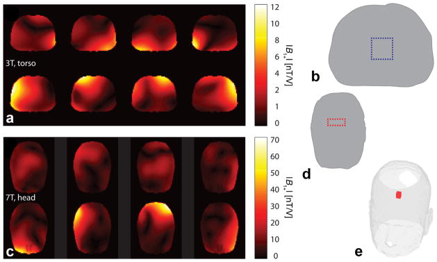
We assessed the performance of our SAR-constrained OC pulse design approach using numerical simulations of a 3T body coil and a 7T head coil. Both eight-channel pTx coils were loaded with the Ansys (Ansys, Canonsburg, PA) adult male model, which contains 33 tissue types. B1,+ maps (Figs. 1a,c), electrical fields, and VOPs (1289 and 361 for the 3T and 7T systems, respectively) were computed as described by Guérin et al. (17). For the 3T simulation of the torso region, pulses were designed with the following SAR/power limits: local SAR, Llim = 8 W/kg, global SAR, Glim = 4 W/kg, and peak power, Plim = 5 kW. For the 7T simulation, these limits were: Llim = 8 W/kg, Glim = 3 W/kg, and Plim = 1 kW. We used the SAR limits set by the U.S. Food and Drug Administration (57). A 10% dutycycle, which effectively scales the SAR limits in Eqs. [6] and [7], was used in all pulse optimizations.
FIG. 1.
The eight-channel B1+ magnitude map simulations shown for the 3T, torso (a) and 7T, head (c) simulations. b,d,e: The target magnetization profiles for those simulations.
The OC algorithm was configured to calculate multidimensional spiral-based spatial-selective pulses for 90° excitation and 180° inversion all with a time-discretization Δt = 10 μs.
The OC algorithm was implemented such that any of the constraints (local SAR, global SAR, and peak power) could be switched on or off independently. To investigate the influence of each constraint type, a total of eight different optimizations, see Figure 2, were performed for each pulse type.
FIG. 2.
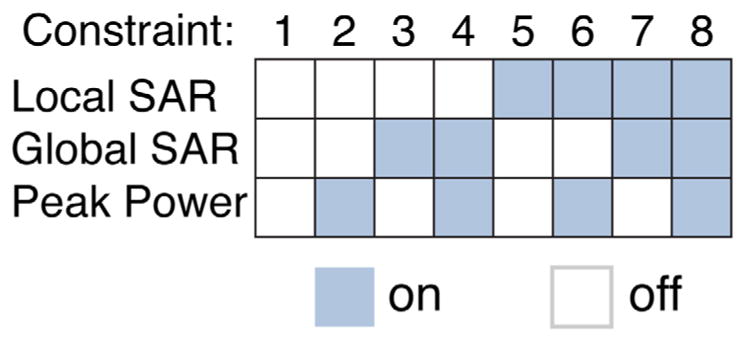
The eight constraint scenarios, denoted 1 to 8, evaluated in this work for each simulation and corresponding to turning on and off a subset of all constraints.
A. Torso, 90° Excitation
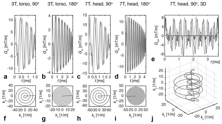
The 2D target Mx-magnetization profile, a square region-of-interest (ROI) is shown Figure 1b and was described on a 64 × 64 grid, where the torso region added up to P = 1604 points. The nominal field-of-excitation (FOX) was 40 × 40 cm2, however, the pulses were optimized with an under-sampling, acceleration factor (AF) of 4 as available by pTx systems under the convention described in Grissom et al. (3). The spiral trajectory and gradient waveform, see Figures 3a,f, was calculated as described by Lustig et al. (58) with limits on the gradient amplitude (Gmax) and slewrate (Smax) set to Gmax = 40 mT/m, Smax = 150 T/m/s. This resulted in a pulse duration T = 1.6 ms. To investigate the impact of the trajectory acceleration, we also optimized the fully constrained pulses with AF = 1, 2, and 3 (trajectories not shown) with T = 5.5, 2.9, and 2.0 ms, respectively.
FIG. 3.
Gradient waveforms (a–e) and k-space trajectories (f–j) used for 3T, torso and 7T, head simulations and optimizations.
B. Torso, 180° Inversion
We used the same ROI and FOX as in A, but the grid size was 32 × 32 (P = 390) to demonstrate the performance of a low resolution pulse, e.g., aimed for coarse volume-suppression. We did not under-sample the k-space. We, furthermore, increased the pulse duration to 4.1 ms by lowering the gradient slewrate limit to 25%, see Figures 3b,g.
C. Head, 90° Excitation
The 2D target magnetization profile was the ROI shown in Figure 1d, the grid size was 64 × 64 (P = 2214), Gmax = 40 mT/m, Smax = 150 T/m/s, and the nominal FOX was 25 × 25 cm2. The pulses were optimized with AF = 4, see Figures 3c,h, and the fully constrained pulses were also optimized with AF = 1, 2, and 3 (trajectories not shown). The pulse durations were T = 6.5, 3.4, 2.3, and 1.9 ms for the AF = 1, 2, 3, and 4, respectively.
D. Head, 180° Inversion
We used the same ROI and FOX as in C, but the grid size was 45 × 45 (P = 1078). We did not accelerate the spiral trajectory or reduce the slewrate. The duration was 4.3 ms, see Figure 3d,i.
E. Head, 90° 3D Excitation
To demonstrate a 3D excitation, we optimized a pulse for exciting the cube shown in Figure 1e, described on a 21 × 21 × 21 grid (P = 4144). We used the spherically-shaped stacked-spiral trajectory analyzed by Asslander et al. (59) using scripts kindly provided by the authors, see Figures 3e,j. We optimized a fully constrained pulse (AF = 4, T = 3.75 ms).
F. Initial Guesses
Every optimization mentioned above was initiated with an up-scaled 30°-pulse designed by the LS algorithm of Guérin et al. (17). The LS optimizations were run with the same constraint scenarios as the OC optimizations except the peak power was always constrained to avoid excessive pulse amplitudes that would otherwise severely hamper the next stage. The constraints were downscaled such that the concurrent up-scaling of the final pulse to either 90° or 180° did not cause a constraint violation. The LS optimizations were given an opportunity to use 105 iterations with a convergence threshold of 1 × 10⁻⁴.
G. Optimizations
The OC framework, blOCh, we present can run parallel computations in several modes. We parallelized the gradient computation because the time-steps are independent, whenever the full forward and backward state propagations are accomplished. Every 2D OC optimization was run with up to 105 iterations to assure convergence to the threshold of 1 × 10⁻⁴ and refinement of the initial guess. The 3D OC optimization had a smaller convergence threshold of 3 × 10⁻⁶ due to the substantially larger grid size.
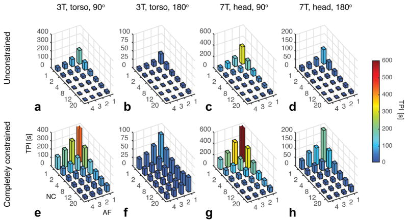
The optimizations were run on a busy computer cluster with a variety of CPU types and memory capacities. Due to MATLAB parallel computation and license issues, we were not able to run all optimizations on the fastest 2.8-GHz Intel-Ivy-Bridge 20-core CPUs (128 GB RAM). Instead the majority of the optimizations were run nonparallel on older 2.3-GHz AMD-Opteron CPUs (16 GB RAM). However, to estimate optimization times, we optimized a range of fully unconstrained and constrained examples with 20 iterations each and a varying number of activated CPU cores (NC = 1, 2, 4, 8, 12, and 20), and for AF = 1, 2, 3, and 4. Besides the 20-iterations limit, the settings were the same as in A to D. Auxiliary optimizations with modified parameters, e.g., the convergence threshold, were done to enlighten the interpretation of our results.
RESULTS
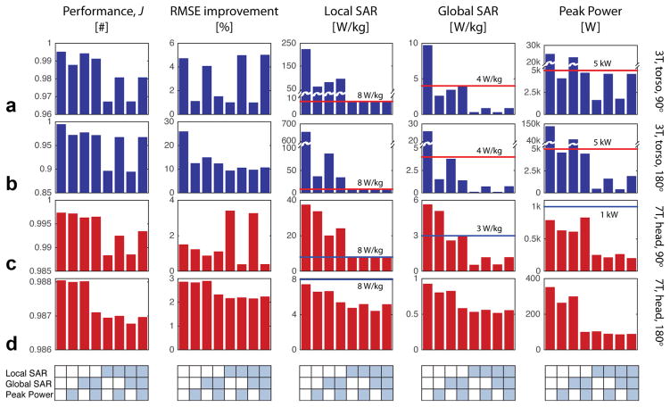
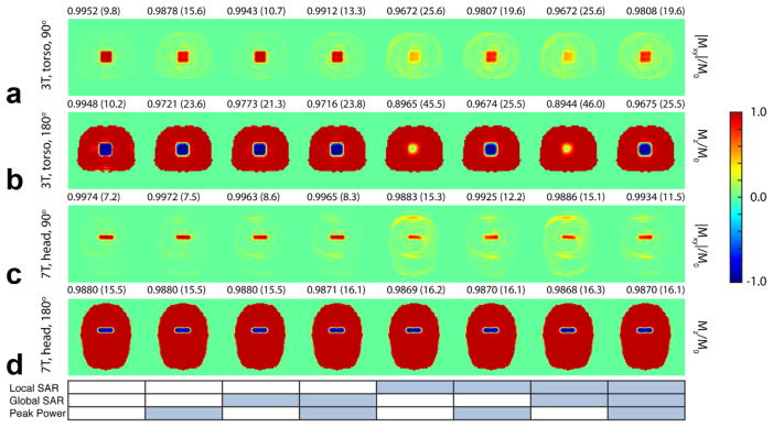
Figure 4 shows the results for 2D spatial-selective pulses. The four rows constitute the main outcome of the four cases described in Methods section A to D. The five panels in each row display the numerical values of the J-metric, root-mean-square error (RMSE) improvement (as compared to the initial state), local SAR, global SAR, and peak power. The eight positions in each panel correspond to the eight constraint scenarios shown in Figure 2. Horizontal lines show the constraint limits. The corresponding magnetization profiles are shown in Figure 5.
FIG. 4.
Bar plots of the performance, RMSE improvement, local SAR, global SAR, and peak power retrieved from the 2D 90° excitation (AF = 4) and 180° inversion (AF = 1) pulses computed for different constraint scenarios in the torso at 3T (a,b) and the head at 7T (c,d). The tables below each column correspond to the constraint scenarios from Figure 2.
FIG. 5.
Simulations of the 3T, torso, 90° (a), 3T, torso, 180° (b), 7T, head, 90° (c), and 7T, head, 180° (d) 2D-pulses. The numbers above each simulation correspond to the performance J-metric and the RMSE percentage in brackets. The table below corresponds to the constraint scenarios from Figure 2.
H. Torso, 90° Excitation, 180° Inversion, and Head, 90° Excitation
It is evident from Figure 4 that a constraint being active always forces the corresponding bar to be less than or equal to the limit, whereas when the constraint was deactivated enables a value above the limit. Bar graphs of the optimization metrics, J, show that the completely unconstrained cases (bars far left) return the highest performance. The local-SAR constraint has the highest impact on the performance, for example, J decreases by approximately 1.4% (3T, 90°), 3% (3T, 180°), and 4‰ (7T, 90°).
In the completely unconstrained cases, local-SAR values are (relative to the 8 W/kg limit) from approximately 47 × (7T, 90°) to more than 816 × (3T, 90°). The global-SAR and peak-power values are in these unconstrained cases also overshooting the limit. Adding either global-SAR or peak-power constraints or both, the local-SAR violations reduce to levels between 3× and 12×. The local-SAR constraint has a relatively high effect on both the global-SAR and peak-power levels. In the head case, however, the peak power was always under the limit.
The RMSE improvement taken as the RMSE of the final pulse compared with the initial guess (the up-scaled STA pulse) shows the advantage of applying the OC algorithm in every case. In the fully constrained torso cases the improvement range from 5 to 10%. In the head case the improvement is 1 to 2%.
Figure 6 shows the RMSE values as a function of the acceleration factor for the fully constrained excitation cases as well as the corresponding magnetization profiles. To enhance the RMSE improvement of the head case (AF = 4) further, we ran the same optimization, however, with a lower convergence tolerance (1 × 10⁻⁵). That led to an RMSE improvement of more than 1% (similar to AF = 1, 2, and 3) for the expense of 62 iterations (20 min, estimated) rather than 41 iterations (11 min).
FIG. 6.
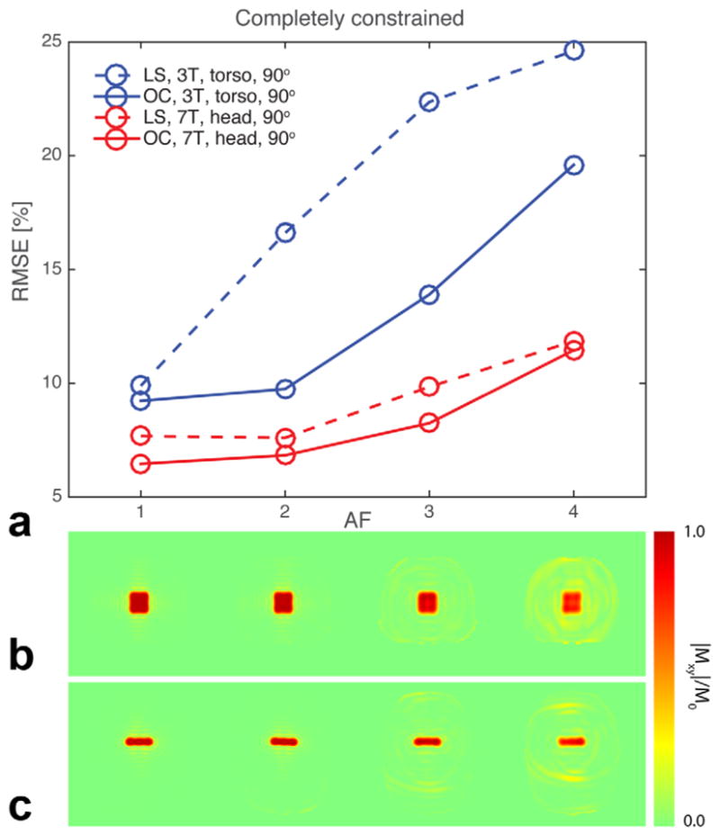
a: Plot of the RMSE values versus the AF for the 2D (blue) 3T, torso, 90°, (red) 7T, head, 90° pulses. The full and dashed lines correspond to the final OC pulses and the initial-guess, up-scaled STA pulses from the LS optimization, respectively. The corresponding magnetization simulations are shown for 3T, torso (b) and 7T, head (c) of the final OC pulses.
I. Head, 180° Inversion
The inversion pulses for the head converged to the threshold of 1 × 10⁻⁴ with relatively low values of local SAR, global SAR and peak power. In fact, the completely unconstrained case did not violate any of these parameters. We optimized the same eight cases with a lower convergence threshold (5 × 10⁻⁶), which did lead to better results (approximately 1% extra RMSE improvements) and similar tendencies for the local-SAR, global-SAR, and peak-power values as the other cases described in the previous section.
J. Head, 90° 3D Excitation
Figure 7 shows a 3D rendering of the magnetization profile from the 3D 90° excitation of a cube in the brain. The optimization time was 1 h for 59 iterations. Similar to the 2D, head, inversion pulse the resulting local-SAR, global-SAR and peak-power levels were far from the limit at iteration 59 (local SAR relatively highest at 50%). Again, an auxiliary optimization with a threshold of 1 × 10⁻⁷ made the local-SAR value saturate, but only for a modest increase of fidelity.
FIG. 7.
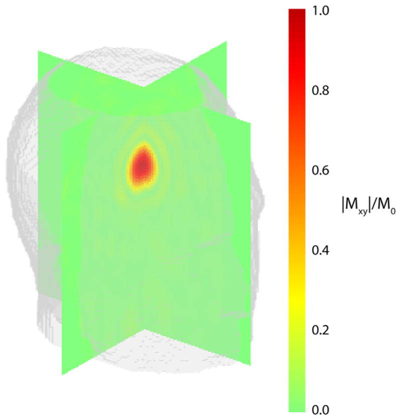
Rendering of the magnetization profile from the fully constrained (AF = 4) 3D pulse.
K. Time-per-Iteration
Figure 8 displays the time-per-iteration (TPI) values obtained as described in the Methods section G. Table 1 lists the iteration numbers and optimization times. Our variety of optimizations differ in the number of VOPs, the number of spatial points, P, and the number of free parameters, which is the product of the number of time-steps, N, the number of pTx channels, C, and 2 (x- and y-amplitudes). How the TPI is affected by these parameters is, therefore, impractical to deduce from the given dataset. We noticed, however, the estimated TPIs should be taken with care for around 50 iterations or more. The TPI increases and is longest in the end of an optimization where the fmincon-optimizer struggles to find the next step.
FIG. 8.
Time-per-iteration (TPI) of the 20-iteration optimizations for AF = 1, 2, 3, and 4, and the number of active CPU cores NC = 1, 2, 4, 8, 12, and 20. The TPI for the completely unconstrained (a–d) and constrained (e–h) optimizations, respectively.
Table 1.
Iteration Numbers and Computation Times for the 2D-Pulse Optimizationsa
| 3T, torso, 90° | 7T, head, 90° | ||||||
|---|---|---|---|---|---|---|---|
|
| |||||||
| Constraint scenario | AF | Iterations | Time [min] | Constraint scenario | AF | Iterations | Time [min] |
| 1 | 4 | 10 | 1.3 | 1 | 4 | 7 | 1.3 |
| 2 | 4 | 12 | 0.8a | 2 | 4 | 7 | 0.8a |
| 3 | 4 | 16 | 1.1a | 3 | 4 | 9 | 1.0a |
| 4 | 4 | 21 | 1.4a | 4 | 4 | 18 | 2.0a |
| 5 | 4 | 20 | 8.8b | 5 | 4 | 14 | 4.5b |
| 6 | 4 | 35 | 15.4b | 6 | 4 | 25 | 8.1b |
| 7 | 4 | 20 | 8.8b | 7 | 4 | 13 | 4.2b |
| 8 | 4 | 34 | 17.8 | 8 | 4 | 41 | 10.9 |
| 8 | 3 | 25 | 14.6c | 8 | 3 | 34 | 16.3c |
| 8 | 2 | 26 | 21.2c | 8 | 2 | 7 | 5.4c |
| 8 | 1 | 21 | 28.7c | 8 | 1 | 7 | 9.8c |
| 3T, torso, 180° | 7T, head, 180° | ||||||
|---|---|---|---|---|---|---|---|
|
| |||||||
| Constraint scenario | AF | Iterations | Time [min] | Constraint scenario | AF | Iterations | Time [min] |
| 1 | 1 | 108 | 5.7 | 1 | 1 | 13 | 2.0 |
| 2 | 1 | 30 | 2.0a | 2 | 1 | 14 | 3.2a |
| 3 | 1 | 58 | 4.0a | 3 | 1 | 13 | 2.9a |
| 4 | 1 | 26 | 1.8a | 4 | 1 | 8 | 1.8a |
| 5 | 1 | 40 | 17.6b | 5 | 1 | 28 | 15.1b |
| 6 | 1 | 58 | 25.5b | 6 | 1 | 8 | 4.3b |
| 7 | 1 | 51 | 22.4b | 7 | 1 | 32 | 17.3b |
| 8 | 1 | 40 | 37.6 | 8 | 1 | 8 | 5.4 |
The letter-marked times correspond to values estimated from the 20-core TPI values of Figure 6:
unconstrained (AF = 4);
fully constrained (AF = 4);
fully constrained (AF = 1, 2, or 3).
DISCUSSION
We have proposed an optimization framework for the design of large-flip-angle pulses subject to SAR and peak-power constraints. The constraints were as in Guérin et al. and Hoyos-Idrobo et al. (17,25) implemented as hard constraints rather than as regularization. Regularization suggests a trade-off between pulse performance and the SAR/power metrics to be constrained, and inapt regularization does not guarantee that the constraints are not violated. Thus, regularization requires careful optimization, for example, through the L-curve method.
Excellent spatial-selective 90° and 180° flip-angle distributions were obtained while constraining the local and global SAR to regulatory levels, as well as the system dependent peak power. We considered two distinct simulations, the difficult torso model in an eight-channel body coil at 3T and the easier head model in an eight-channel head coil at 7T. Both simulations were subject to every possible constraint scenario to investigate the influence of each individual constraint on the pulse performance. The 90° pulses were, furthermore, optimized with acceleration factors up to 4.
An important conclusion of this work is that when not constraining local SAR, its level increases in most cases far beyond the tolerable limit. This echoes the conclusion of the work of Guérin et al. (17) but extends it to the large-flip-angle regime (we studied 90° and 180° pulses in this work). As expected, the local SAR violations when only controlling peak power (i.e., no local SAR constraints) are much more dramatic in the LTA regime than in the STA regime. With LTA, we found that local SAR hot-spots could be as high as 740% (425%) of the tolerated limit with the torso at 3T (head at 7T) using only peak power constraints. Constraining local SAR came at the cost of slightly decreased excitation quality (as measured by the J-metric and RMSE). For the 90°/180° torso pulses, J decreased only by a few percent, which corresponds to RMSEs increasing 5 to 10%. For the 90°/180° head pulses, J decreased only by a few parts per thousand, which corresponds to RMSEs increasing only a few percent.
As concluded in Guérin et al. (17), a local-SAR constraint may help to limit global SAR, but the opposite may not be true. In our study, the global-SAR constraint was never capable of limiting the local SAR sufficiently, when the unconstrained local SAR was approaching a high level. This was observed both with and without the peak-power constraint. The local-SAR constraint, however, did a good job constraining the global SAR to benign levels. Another finding was that the enforced local-SAR constraint in the head simulation actually yielded peak-power levels well below the 1-kW limit. However, in the torso excitation case, the peak power needed constraining even though the local-SAR constraint was enforced. The peak-power constraint is not computationally demanding or difficult to comply with, and we therefore suggest constraining the peak power in general. Unconstrained local-SAR levels were in total higher in the torso model than in the head model. This is due to the fact that the torso model had a much more complicated electrical field pattern than the head model because of the increased complexity of the torso geometry. Hence, the risk of generating local hot-spots is higher even at lower power levels. This means that the local SAR level cannot be controlled efficiently in a model with this complex electrical field pattern. The head model has more uniform electrical field patterns thus making the local SAR more coupled to power metrics. However, as mentioned, the peak-power or global-SAR control is not always enough to limit local SAR even in the head model for the pulses that we have investigated.
Our convergence thresholds were based on experience. We saw that lowering the thresholds, i.e., to improve the pulse performances slightly through additional iterations, enforced the SAR and peak-power values to increase to their limits or possibly to unpredictable high levels if not limited. However, the global-SAR values still remained benign whenever the local-SAR constraint was enforced.
We observed a poor performance, e.g., for the 3T, torso, 90° pulses in Figure 5b, position 5 and 7, whenever the local-SAR and the peak-power constraints were activated and deactivated, respectively. We reason this as a competition internally in the algorithm between the opposite-directed local-SAR and peak-power metrics. The problem seems to vanish for longer pulse durations, where higher amplitudes depraving the local SAR are not anticipated to the same extend.
Previous work by Vinding et al. (31) was committed to thorough investigations of fast MRI OC procedures including GRAPE-BFGS with gradients precise to first order, i.e., computationally fast, but suboptimal as the inverse-Hessian matrix estimation indeed was corrupted by the approximated gradients. However, Maximov et al. (37) later showed satisfactory in vivo results with the first-order GRAPE-BFGS. In this study, we checked if the first-order gradients could replace the exact gradients, but when, e.g., the local-SAR constraints was activated we observed convergence to infeasible points. Hoyos-Idrobo et al. (25) efficiently applied finite-difference gradients for their LTA MLS problem. Finite-difference gradients are inexpensive to compute in OC as well, as they only (depending on precision) require few extra state-propagations. Hence, brute-force estimation can be avoided (51). However, the BFGS approach performs even better with exact gradients than with fourth-order finite-difference gradients (51) why it was implemented here as in Floether et al. (52).
We compared GRAPE-BFGS with GRAPE-L-BFGS and found the latter to be few percent faster for the same performance, probably because the number of free parameters is sufficiently low for BFGS to work properly (51). We also chose the L-BFGS variant to avoid potential memory conflicts, because the local-SAR and the exact-gradient computations do indeed occupy large memory portions.
We have shown that dramatic reductions in optimization times can be accomplished by using 4 CPU cores or more, which is becoming more and more available. Further time savings may be achieved by using GPUs for fast computations as done, e.g., in Ref. (25). We did not have GPUs readily available for the current study. However, we intend to apply GPUs in future versions of blOCh as we expect significant improvements. This lift is indeed needed for, say, 3D excitation pulses.
CONCLUSIONS
An OC framework for designing multidimensional, multichannel, large-tip-angle pulses handling hard constraints of local SAR, global SAR, and peak power has been presented. We simulated two eight-channel systems loaded with a numerical phantom, a torso in a 3T body coil, and a head in 7T head coil. The presented numerical data clearly demonstrates a large-flip-angle pulse design with the ability to constrain local SAR by means of VOPs and global SAR to within guidelines for a duty-cycle of 10%, while at the same time limiting the peak power to hardware tolerated levels.
Acknowledgments
Grant sponsor: the Danish National Research Foundation; Grant number: DNRF59; Grant sponsor: the Ministry of Higher Education and Science; Grant number: AU-2010-612-181; Grant sponsor: Innovation Fund Denmark; Grant number: 0603-00439B.
We are thankful to Dr. I. Maximov and Prof. I. Kuprov for discussions on the OC procedures and N.C.W. Hansen for HPC-support. We acknowledge support from the Danish National Research Foundation, the Danish Council for Strategic Research, the Lundbeck Foundation, the Danish Center for Scientific Computing, the Ministry of Higher Education and Science, Aarhus University Research Foundation, and the Programme Commission on Strategic Growth Technologies, and Innovation Fund Denmark.
References
- 1.Katscher U, Bornert P, Leussler C, van den Brink JS. Transmit SENSE. Magn Reson Med. 2003;49:144–150. doi: 10.1002/mrm.10353. [DOI] [PubMed] [Google Scholar]
- 2.Zhu Y. Parallel excitation with an array of transmit coils. Magn Reson Med. 2004;51:775–784. doi: 10.1002/mrm.20011. [DOI] [PubMed] [Google Scholar]
- 3.Grissom WA, Yip C, Zhang Z, Stenger VA, Fessler JA, Noll DC. Spatial domain method for the design of RF pulses in multicoil parallel excitation. Magn Reson Med. 2006;56:620–629. doi: 10.1002/mrm.20978. [DOI] [PubMed] [Google Scholar]
- 4.Setsompop K, Wald LL, Alagappan V, Gagoski B, Hebrank F, Fontius U, Schmitt F, Adalsteinsson E. Parallel RF transmission with eight channels at 3 Tesla. Magn Reson Med. 2006;56:1163–1171. doi: 10.1002/mrm.21042. [DOI] [PubMed] [Google Scholar]
- 5.Xu D, King KF, Zhu Y, McKinnon GC, Liang Z-P. Designing multi-channel, multidimensional, arbitrary flip angle RF pulses using an optimal control approach. Magn Reson Med. 2008;59:547–560. doi: 10.1002/mrm.21485. [DOI] [PMC free article] [PubMed] [Google Scholar]
- 6.Schneider JT, Kalayciyan R, Haas M, Herrmann SR, Ruhm W, Hennig J, Ullmann P. Inner-volume imaging in vivo using three-dimensional parallel spatially selective excitation. Magn Reson Med. 2013;69:1367–1378. doi: 10.1002/mrm.24381. [DOI] [PubMed] [Google Scholar]
- 7.Malik SJ, Larkman DJ, O’Regan DP, Hajnal JV. Subject-specific water-selective imaging using parallel transmission. Magn Reson Med. 2010;63:988–997. doi: 10.1002/mrm.22260. [DOI] [PubMed] [Google Scholar]
- 8.Malik SJ, Keihaninejad S, Hammers A, Hajnal JV. Tailored excitation in 3D with spiral nonselective (SPINS) RF pulses. Magn Reson Med. 2012;67:1303–1315. doi: 10.1002/mrm.23118. [DOI] [PubMed] [Google Scholar]
- 9.Cloos MA, Boulant N, Luong M, Ferrand G, Giacomini E, Le Bihan D, Amadon A. kT-points: short three-dimensional tailored RF pulses for flip-angle homogenization over an extended volume. Magn Reson Med. 2012;67:72–80. doi: 10.1002/mrm.22978. [DOI] [PubMed] [Google Scholar]
- 10.Poser BA, Anderson RJ, Guérin B, Setsompop K, Deng W, Mareyam A, Serano P, Wald LL, Stenger VA. Simultaneous multislice excitation by parallel transmission. Magn Reson Med. 2014;71:1416–1427. doi: 10.1002/mrm.24791. [DOI] [PMC free article] [PubMed] [Google Scholar]
- 11.Center for Devices and Radiological Health. Criteria for significant risk investigations of magnetic resonance diagnostic devices. Rockville, MD: Food and Drug Administration; 2003. [Google Scholar]
- 12.Center for Devices and Radiologic Health. Guidance for the submission of premarket notifications for magnetic resonance diagnostic devices. Rockville, MD: Food and Drug Administration; 1998. [Google Scholar]
- 13.IEC. Particular requirements for the safety of magnetic resonance equipment for medical diagnosis. 3. Geneva: IEC; 2011. International Standard I. [Google Scholar]
- 14.Eichfelder G, Gebhardt M. Local specific absorption rate control for parallel transmission by virtual observation points. Magn Reson Med. 2011;66:1468–1476. doi: 10.1002/mrm.22927. [DOI] [PubMed] [Google Scholar]
- 15.International Electrotechnical Commission. International standard, Medical equipment - part 2: particular requirements for the safety of magnetic resonance equipment for medical diagnosis, 2nd revision. Geneva: International Electrotechnical Commission; 2002. [Google Scholar]
- 16.International Electrotechnical Commission. IEC Standard 60601-2-33, Particular requirements for the safety of magnetic resonance equipment for medical diagnosis. Chicago: International Electrotechnical Commission; 2004. [Google Scholar]
- 17.Guérin B, Gebhardt M, Cauley S, Adalsteinsson E, Wald LL. Local specific absorption rate (SAR), global SAR, transmitter power, and excitation accuracy trade-offs in low flip-angle parallel transmit pulse design. Magn Reson Med. 2014;71:1446–1457. doi: 10.1002/mrm.24800. [DOI] [PMC free article] [PubMed] [Google Scholar]
- 18.Boulant N, Wu X, Adriany G, Schmitter S, Ugurbil K, Van de Moortele P-F. Direct control of the temperature rise in parallel transmission via temperature virtual observation points: simulations at 10.5 T. In proceedings of the 23rd Annual Meeting of ISMRM; Toronto, Canada. 2015. p. Abstract 0548. [DOI] [PMC free article] [PubMed] [Google Scholar]
- 19.Pendse M, Rutt B. An algorithm for maximum-SAR targeted RF hyperthermia. In proceedings of the 23rd Annual Meeting of ISMRM; Toronto, Canada. 2015. p. Abstract 3224. [Google Scholar]
- 20.Brunner DO, Pruessmann KP. Optimal design of multiple-channel RF pulses under strict power and SAR constraints. Magn Reson Med. 2010;63:1280–1291. doi: 10.1002/mrm.22330. [DOI] [PubMed] [Google Scholar]
- 21.Cloos MA, Luong M, Ferrand G, Amadon A, Le Bihan D, Boulant N. Local SAR Reduction in parallel excitation based on channel-dependent tikhonov parameters. J Magn Reson Imaging. 2010;32:1209–1216. doi: 10.1002/jmri.22346. [DOI] [PubMed] [Google Scholar]
- 22.Lee J, Gebhardt M, Wald LL, Adalsteinsson E. Local SAR in Parallel transmission pulse design. Magn Reson Med. 2012;67:1566–1578. doi: 10.1002/mrm.23140. [DOI] [PMC free article] [PubMed] [Google Scholar]
- 23.Sbrizzi A, Hoogduin H, Lagendijk JJ, Luijten P, Sleijpen GLG, van den Berg CAT. Fast design of local N-gram-specific absorption rate–optimized radiofrequency pulses for parallel transmit systems. Magn Reson Med. 2012;67:824–834. doi: 10.1002/mrm.23049. [DOI] [PubMed] [Google Scholar]
- 24.Guérin B, Setsompop K, Ye H, Poser BA, Stenger AV, Wald LL. Design of parallel transmission pulses for simultaneous multislice with explicit control for peak power and local specific absorption rate. Magn Reson Med. 2015;73:1946–1953. doi: 10.1002/mrm.25325. [DOI] [PMC free article] [PubMed] [Google Scholar]
- 25.Hoyos-Idrobo A, Weiss P, Massire A, Amadon A, Boulant N. On variant strategies to solve the magnitude least squares optimization problem in parallel transmission pulse design and under strict SAR and power constraints. IEEE Trans Med Imaging. 2014;33:739–748. doi: 10.1109/TMI.2013.2295465. [DOI] [PubMed] [Google Scholar]
- 26.Yetisir F, Guérin B, Wald LL, Adalsteinsson E. Direct control of the temperature rise in parallel transmission via temperature virtual observation points: simulations at 10.5 T. In proceedings of the 22nd Annual Meeting of ISMRM; Milan, Italy. 2014. p. Abstract 0548. [Google Scholar]
- 27.Pontryagin L, Boltyanskii B, Gamkrelidze R, Mishchenko E. The mathematical theory of optimal processes. New York: Interscience, a division of John Wiley; 1962. [Google Scholar]
- 28.Setsompop K, Wald LL, Alagappan V, Gagoski BA, Adalsteinsson E. Magnitude least squares optimization for parallel radio frequency excitation design demonstrated at 7 Tesla with eight channels. Magn Reson Med. 2008;59:908–915. doi: 10.1002/mrm.21513. [DOI] [PMC free article] [PubMed] [Google Scholar]
- 29.Maximov II, Tošner Z, Nielsen NC. Optimal control design of NMR and dynamic nuclear polarization experiments using monotonically convergent algorithms. J Chem Phys. 2008;128:184505. doi: 10.1063/1.2903458. [DOI] [PubMed] [Google Scholar]
- 30.Maximov II, Salomon J, Turinici G, Nielsen NC. A smoothing monotonic convergent optimal control algorithm for nuclear magnetic resonance pulse sequence design. J Chem Phys. 2010;132:084107. doi: 10.1063/1.3328783. [DOI] [PubMed] [Google Scholar]
- 31.Vinding MS, Maximov II, Tošner Z, Nielsen NC. Fast numerical design of spatial-selective rf pulses in MRI using Krotov and quasi-Newton based optimal control methods. J Chem Phys. 2012;137:054203. doi: 10.1063/1.4739755. [DOI] [PubMed] [Google Scholar]
- 32.Conolly SM, Nishimura DG, Macovski A. Optimal control solutions to the magnetic resonance selective excitation problem. IEEE Trans Med Imaging. 1986;5:106–115. doi: 10.1109/TMI.1986.4307754. [DOI] [PubMed] [Google Scholar]
- 33.Hestenes MR, Stiefel E. Methods of conjugate gradients for solving linear systems. J Res Natl Bur Stand. 1952;49:409–436. [Google Scholar]
- 34.Hansen P. Regularization tools: a Matlab package for analysis and solution of discrete ill-posed problems. Numer Algorithms. 1994;6:1–35. [Google Scholar]
- 35.Pauly JM, Nishimura DG, Macovski A. A linear class of large-tip-angle selective excitation pulses. J Magn Reson. 1989;82:571–587. [Google Scholar]
- 36.Pauly JM, Roux PL, Nishimura DG, Macovski A. Parameter relations for the Shinnar-Le Roux selective excitation pulse design algorithm. IEEE Trans Med Imaging. 1991;10:53–65. doi: 10.1109/42.75611. [DOI] [PubMed] [Google Scholar]
- 37.Maximov II, Vinding MS, Tse DHY, Nielsen NC, Shah NJ. Real-time 2D spatially selective MRI experiments: comparative analysis of optimal control design methods. J Magn Reson. 2015;254:110–120. doi: 10.1016/j.jmr.2015.03.003. [DOI] [PubMed] [Google Scholar]
- 38.Grissom WA, Xu D, Kerr AB, Fessler JA, Noll DC. Fast large-tip-angle multidimensional and parallel RF pulse design in MRI. IEEE Trans Med Imaging. 2009;28:1548–1559. doi: 10.1109/TMI.2009.2020064. [DOI] [PMC free article] [PubMed] [Google Scholar]
- 39.Holbach M, Lambert J, Johst S, Ladd ME, Suter D. Optimized selective lactate excitation with a refocused multiple-quantum filter. J Magn Reson. 2015;255:34–38. doi: 10.1016/j.jmr.2015.03.004. [DOI] [PubMed] [Google Scholar]
- 40.Holbach M, Lambert J, Suter D. Optimized multiple-quantum filter for robust selective excitation of metabolite signals. J Magn Reson. 2014;243:8–16. doi: 10.1016/j.jmr.2014.03.007. [DOI] [PubMed] [Google Scholar]
- 41.Lapert M, Zhang Y, Janich MA, Glaser SJ, Sugny D. Exploring the physical limits of saturation contrast in magnetic resonance imaging. Sci Rep [Internet] 2012;2 [Google Scholar]
- 42.Matson GB, Young K, Kaiser LG. RF pulses for in vivo spectroscopy at high field designed under conditions of limited power using optimal control. J Magn Reson. 2009;199:30–40. doi: 10.1016/j.jmr.2009.03.010. [DOI] [PMC free article] [PubMed] [Google Scholar]
- 43.Vinding MS, Laustsen C, Maximov II, Søgaard LV, Ardenkjær-Larsen JH, Nielsen NC. Dynamic nuclear polarization and optimal control spatial-selective 13C MRI and MRS. J Magn Reson. 2013;227:57–61. doi: 10.1016/j.jmr.2012.12.002. [DOI] [PubMed] [Google Scholar]
- 44.Khaneja N, Reiss T, Kehlet C, Schulte-Herbruggen T, Glaser SJ. Optimal control of coupled spin dynamics: design of NMR pulse sequences by gradient ascent algorithms. J Magn Reson. 2005;172:296–305. doi: 10.1016/j.jmr.2004.11.004. [DOI] [PubMed] [Google Scholar]
- 45.Liu DC, Nocedal J. Updating quasi-Newton Matrices with limited storage. Math Comp. 1980;35:773–782. [Google Scholar]
- 46.Liu DC, Nocedal J. On the limited memory BFGS method for large scale optimization. Math Prog. 1989;45:503–528. [Google Scholar]
- 47.Broyden CG. The convergence of a class of double-rank minimization algorithms. J Inst Math Appl. 1970;6:76–90. [Google Scholar]
- 48.Fletcher R. A new approach to variable metric algorithms. Comput J. 1970;13:317–322. [Google Scholar]
- 49.Goldfarb D. A family of variable metric updates derived by variational means. Math Comp. 1970;24:23–26. [Google Scholar]
- 50.Shanno DF. Conditioning of quasi-Newton methods for function minimization. Math Comp. 1970;24:647–656. [Google Scholar]
- 51.De Fouquieres P, Schirmer SG, Glaser SJ, Kuprov I. Second order gradient ascent pulse engineering. J Magn Reson. 2011;212:412–417. doi: 10.1016/j.jmr.2011.07.023. [DOI] [PubMed] [Google Scholar]
- 52.Floether FF, de Fouquieres P, Schirmer SG. Robust quantum gates for open systems via optimal control: Markovian versus non-Markovian dynamics. New J Phys. 2012;14:073023. [Google Scholar]
- 53.Byrd RH, Hribar ME, Nocedal J. An interior point algorithm for large-scale nonlinear programming. SIAM J Optim. 1999;9:877–900. [Google Scholar]
- 54.Majewski K, Ritter D. First and second order derivatives for optimizing parallel RF excitation waveforms. J Magn Reson. 2015;258:65–80. doi: 10.1016/j.jmr.2015.06.010. [DOI] [PubMed] [Google Scholar]
- 55.Moler C, Van Loan C. Nineteen dubious ways to compute the exponential of a matrix, twenty-five years later. SIAM Rev. 2003;45:3–49. [Google Scholar]
- 56.Sidje RB. EXPOKIT: software package for computing matrix exponentials. Trans Math Softw. 1998;24:130–156. [Google Scholar]
- 57.Zaremba LA. Guidance for industry and FDA staff: criteria for significant risk investigations of magnetic resonance diagnostic devices. Rockville, MD: US Department of Health and Human Services, Food and Drug Administration; 2003. [Google Scholar]
- 58.Lustig M, Kim Seung-Jean, Pauly JM. A fast method for designing time-optimal gradient waveforms for arbitrary k-space trajectories. IEEE Trans Med Imaging. 2008;27:866–873. doi: 10.1109/TMI.2008.922699. [DOI] [PMC free article] [PubMed] [Google Scholar]
- 59.Asslander J, Zahneisen B, Hugger T, Reisert M, Lee H-L, LeVan P, Hennig J. Single shot whole brain imaging using spherical stack of spirals trajectories. Neuroimage. 2013;73:59–70. doi: 10.1016/j.neuroimage.2013.01.065. [DOI] [PubMed] [Google Scholar]


