Abstract
The objective of this research was to use computer-aided design software and a tabletop 3-D additive manufacturing system to design and fabricate custom plastic inserts for trans-tibial prosthesis users. Shape quality of inserts was tested right after they were inserted into participant’s test sockets and again after four weeks of wear. Inserts remained properly positioned and intact throughout testing. Right after insertion the inserts caused the socket to be slightly under-sized, by a mean of 0.11 mm, approximately 55% of the thickness of a nylon sheath. After four weeks of wear the under-sizing was less, averaging 0.03 mm, approximately 15% of the thickness of a nylon sheath. Thus the inserts settled into the sockets over time. If existing prosthetic design software packages were enhanced to conduct insert design and to automatically generate fabrication files for manufacturing, then computer manufactured inserts may offer advantages over traditional methods in terms of speed of fabrication, ease of design, modification, and record keeping.
INTRODUCTION
Computer aided socket design and manufacturing (CAD/CAM) was introduced to prosthetics in the 1980’s [1,2]. CAD/CAM has matured over the past 30 years into a complete fabrication technology. It is used regularly by approximately 24% of prosthetists to make sockets for people with limb loss [3]. Using a digitized shape of the residual limb as a starting point, the prosthetist designs the socket shape, implementing software specific for prosthetic socket design. Once the shape file is created, a socket is fabricated by carving a positive model and then thermoforming a socket or by using a direct fabrication technique [4]. Compared with traditional socket design and fabrication methods, CAD/CAM offers advantages in terms of speed of fabrication, ease of design modification, and record keeping [5].
The purpose of this research was to extend CAD/CAM to the design and manufacturing of stiff socket inserts. Socket inserts are typically used to modify instead of replace sockets. CAD/CAM of inserts may offer advantages over traditional insert design and fabrication methods, similar to how they do so with prosthetic sockets. As a first step towards this objective, we present methods for design and fabrication of computer-manufactured plastic inserts. Results testing shape accuracy and performance on people with trans-tibial limb loss are presented.
METHODS
Inserts were fabricated in three steps. First, the socket to receive the insert was digitized and a computer 3-dimensional (3-D) surface generated. This surface was the insert external shape. Then computer aided design software was used to design the insert internal shape and to generate a solid model. A solid model was necessary so as to use 3-D additive manufacturing technology for fabrication. The insert was fabricated in three pieces that interlocked together and fit within the prosthetic socket.
Creating the insert external surface shape
The insert external surface was designed to match the existing socket internal surface. To shape the insert, first the internal socket shape to receive the insert was measured.
Scan internal socket shape
To digitize the inside socket surface, we used a high-quality industry digitizer (FaroArm Platinum, FARO Technologies, Lake Mary, Florida) mounted within a custom frame and base (FIGURE 1). A 6.00mm diameter scanning tip was used for all sockets in the present study. The base held a standard pyramid adaptor so that a socket could be firmly secured with its longitudinal axis oriented vertically. Data acquisition software provided with the scanner (Geomagic, Design X, 3D Systems, Rock Hill, South Carolina) was implemented. The manufacturer also provided a calibration jig that we attached to the frame. Calibration was performed before each use.
FIGURE 1.
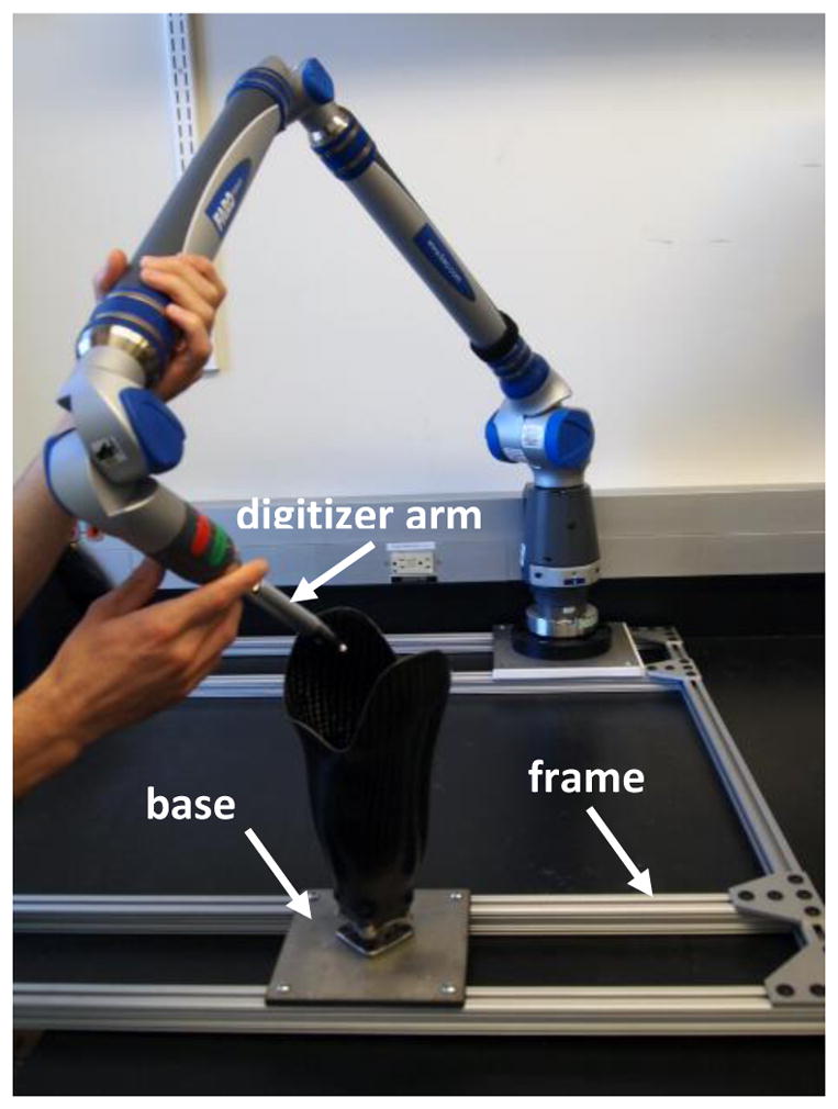
Custom frame and base used for socket digitization
We scanned points on the inside of the socket at the brim and at the distal end, and fit a spline to each set of points so as to establish the upper and lower contours of the socket (FIGURE 2a) (Scanner Accuracy was set to 0.02mm). With the scanner in a point cloud acquisition mode, we then sequentially scanned patch regions of the socket until the complete socket shape between the brim and bottom surface was digitized (FIGURE 2b).
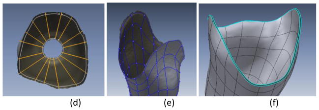
FIGURE 2a–f. Socket digitization and model formation.
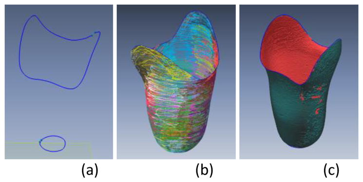
(a) Splines at the socket proximal and distal end. (b) Scanned patch regions of the socket. Each patch is a different color. (c) Holes in the scanned socket surface resulting from the digitization process. The holes illustrated are minor; additional scanning does not need to be performed for this socket. (d) Top-view of the socket illustrating axial splines. (e) Socket defined as a collection of 4-sided sections. (f) Solid model of a uniform thickness insert ready for fabrication.
The collected data was visually inspected to identify and remove any outlier points that were not near the surface formed by the cloud (e.g., from the scanner arm skipping out of the socket at the proximal edge). If there were large holes of no data points in a region then additional scanning in that region was conducted.
Create mesh
Once the shape was visually acceptable on the computer screen, the Construct Mesh function in the software was used to create an adaptive spherical covering over the point cloud. Each sphere contained one or more of the original points and generated a single new auxiliary point based on the mesh density and relative location of the neighboring points. When every original point was encompassed within a sphere, auxiliary points within three intersecting spheres were connected to create a face. Redundant faces were removed, creating an entire mesh [6](FIGURE 2c).
Additional scanning was conducted if there were large holes, and the surface was re-meshed. The Rewrap function in the software was executed which used adaptive basis functions to create a new point structure [7]. User input values for mesh edge lengths, capture accuracy, overall smoothing factor, and mesh density in high curvature areas were included in the algorithm.
Because the scanner recorded the position of the center of the ball at the end of the probe, not the outer surface where the ball contacted the socket, we offset the data outward a distance the radius of the ball (6.0 mm) to create the true socket surface.
Create 3-D surface
The mesh was converted to a 3-D surface so that a solid model could be generated. To do this step, we drew axial splines (FIGURE 2d) and perimeter splines (FIGURE 2e) onto the mesh so that the socket was defined as a collection of 4-sided sections. A boundary fit command was executed which created a series of fitted closed contours from the mesh.
Design insert
Uniform thickness insert
With the external shape of the insert defined as a 3-D surface, we projected inward normals to create a second surface, the internal shape of the insert, as well as two other surfaces, the proximal edge and the distal edge. If an insert was to be of uniform thickness, these manipulations were easily executed using the software. The four surfaces were grouped together to create a solid model (FIGURE 2f) that was then converted to STL format in preparation for fabrication.
Non-uniform thickness insert
To design a non-uniform insert, the shape was imported into a commercial prosthetics software package (e.g., TracerCAD, Willow Wood, Mt. Sterling, Ohio), modified, and then exporting back into the software described above.
Insert separated into three sections
To allow large inserts to be fabricated, to minimize use of support material (Support 705, Stratasys, Eden Prairie, Minnesota) during 3-D additive fabrication, and to simplify placing the insert into the socket, we split the insert into three sections as illustrated in FIGURE 3a, using Inventor software (Autodesk, San Rafael, California). The boundary between the anterior insert pieces was selected to align with the tibial crest. The other two boundaries were positioned posterior-laterally and posterior-medially so that the posterior insert section was the posterior aspect of the socket. The three sections were prepared so that there was an approximately 0.60mm gap between adjacent edges. This gap was necessary to ensure the sections did not overlap when positioned within the socket. The insert proximal edges were skived to avoid sharp edges at the brim that might damage the prosthetic liner. Interlocking tabs were formed midway down the lengths of the sections so that they locked together properly when positioned within the socket (FIGURE 3b). An STL file was created for each of the three sections in preparation for fabrication.
FIGURE 3a,b. Sectioning an insert for fabrication.
(a) The insert was sectioned such that one boundary was at the tibial crest and the others posterior laterally and posterior medially. (b) Interlocking tabs were designed so that the inserts locked together when placed within the prosthetic socket.
Fabricate insert & place in socket
The insert sections were fabricated using a tabletop additive fabrication system (Objet30 Pro, Stratasys, Eden Prairie, Minnesota). This system created a solid object from an STL file by adding polymer and supporting casting material in successive layers. Inserts up to a length of 30 cm could be fabricated. A rigid opaque polymer (VeroBlue RGD840, Stratasys) was used to make the inserts. We selected this polymer because it was hard and durable with acceptable mechanical properties (similar to Delrin® (DuPont, Wilmington, Delaware)). We printed inserts with a Gloss Finish setting on the inside surface to improve smoothness and durability. To position the inserts within the socket, we applied two-sided laminating tape (SpeedTape, FastCap, Ferndale, Washington) to the backside edges of each insert section (FIGURE 4a). The three sections were then assembled into the socket (FIGURE 4b,c).
FIGURE 4a–c. Insert placed within prosthetic socket.
(a) Two-sided laminating tape was applied to the proximal and distal edges of each insert piece. (b) Insert pieces were placed in the socket, one at a time. (c) Insert pieces interlocked once in place.
Testing of shape quality
To test shape quality of the insert, we compared the internal shape of the insert installed within the prosthetic socket with the original digital shape file. The insert internal shape was measured using the same industrial digitizer as described above.
We aligned the insert and digital shapes for comparison using a technique we developed previously to compare shapes [8,9]. The technique used a combination of minimizing the volume difference and maximizing the shape similarity and was specifically formulated for use in prosthetics. The entire surface below the level of the trimlines was included in the analysis.
After the shapes were aligned, we calculated the volume in between the two shapes and expressed the result as a percentage of the digital shape volume below the trimlines. We also calculated the following: percentage of points on the insert within 1.00mm of the digital surface; minimum radial error; maximum radial error; mean radial error; and standard deviation of the mean radial error.
As described below we conducted similar testing after the inserts were worn by prosthesis users for 4 weeks.
Amputee Participant Use Testing
We conducted amputee participant testing to evaluate shape quality after field use. The basis for this testing was that we suspected inserts settled into the socket over time and we sought to determine to what degree that affected shape quality.
Participants
Institutional review board approval and informed consent were obtained before study procedures were initiated. Volunteers were considered for inclusion if they had a trans-tibial amputation more than 12 months prior and were at a Medicare Functional Classification Level (MFCL) of K-2 or higher (at least a limited community-level ambulator). Participants were required to use a prosthetic limb for an average of at least 4 hours per day, determined by self-report. Participants were not included if they were currently experiencing skin breakdown on their residual limb.
The participant’s socket fit was evaluated by the research prosthetist. If the fit was deemed acceptable for regular clinical use, sock thickness was measured using a custom instrument [10]. If sock thickness was less than 1.8mm (approximately the thickness of a new 5-ply sock under weight-bearing) then the participant was continued in the study, and a new socket and insert were created. The new socket was 1.8mm larger than the participant’s regular socket so as to accommodate the insert’s 1.8mm thickness. Thus we made the test prosthesis with insert the same shape as the participant’s regular prosthesis.
Socket and insert fabrication
The high-quality industry digitizer mounted within the custom frame and base described above (FIGURE 1) was used to digitize the participant’s socket. After the shape was collected, we used computer design software to project the surface radially outward 1.8mm and create the internal surface of the socket to be fabricated. That shape was then sent to a central fabrication facility to fabricate a foam positive. We used the foam positive to make a carbon-fiber laminated socket, using a vacuum infusion process on a low-viscosity acrylic epoxy resin (EAR1, ACSYS Orthopedic, Vista, California). Sockets were constructed with inner and outer layers of 45 degree braided carbon fiber with 12,000 filaments per tow (W56L600B30, A&P Technology Inc., Cincinnati, Ohio) and an inner core of four layers of nyglass (NyGlass Stockinette, Rx Textiles, Monroe, North Carolina).
An insert of thickness 1.8mm was designed and fabricated for the new socket using the procedures described above. The participant returned to the laboratory so that their regular shank and foot could be switched to the new socket and the prosthesis test fitted. Because we maintained alignment during the socket fabrication process, the prosthesis did not need to be realigned.
Testing Protocol
Participants wore the sockets with inserts for a period of 4 weeks. After 4 weeks of use of the test prosthesis, the participant returned to the laboratory, the test socket was removed, and the participant’s regular socket was put back on the prosthesis. We carefully looked for flaws in the adhesive at the junctions of the insert pieces. Photographs were taken to document insert condition. The inside shape of the socket with insert was digitized using procedures described above.
Data Analysis
We aligned the 4-week inserts and digital shapes for comparison using the same methods as described above. We calculated the same analysis variables as for the new insert to digital shape comparisons.
RESULTS
Once the researcher became proficient using the digitizer software, the total time required to scan the prosthesis user’s socket and design the insert was approximately 100 minutes. Approximately 40 of the 100 minutes were required for scanning, and 60 minutes for computer design. Each of the three insert sections of a socket took between 6 and 13 hours to fabricate, depending upon size. It took less than 10 minutes to apply the adhesive tape and place the inserts within the socket.
Uniform thickness inserts of 1.8mm thickness were tested by five participants. Characteristics of the five participants are listed in TABLE 1. The mass of polymer used for the all three sections of each insert ranged from 94 kg to 147 kg, with a mean of 121 (±25) kg.
TABLE 1.
Participant Characteristics.
| Participant # | Age (yr) | Height (cm) | Mass (kg) | Time since Amputation (yr) | Residual Limb Length (cm) |
|---|---|---|---|---|---|
| 1 | 52 | 167.6 | 85.3 | 6 | 13.3 |
| 2 | 69 | 185 | 93.6 | 39 | 12.5 |
| 3 | 48 | 180.3 | 76.8 | 21 | 17.0 |
| 4 | 51 | 182.9 | 100 | 25 | 10.0 |
| 5 | 71 | 155 | 61 | 5 | 12.0 |
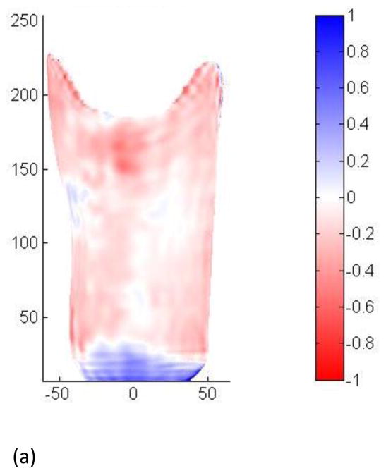
Sockets with inserts measured right after insertion into the socket were consistently undersized compared with the designed insert (TABLE 2). The mean volume difference between the fabricated insert and the designed insert was −0.38%. Mean radial error was −0.11mm. The distribution of shape difference was reasonably uniform over the surface (FIGURE 5a).
TABLE 2.
Fabricated Insert Right after Installation Compared with Designed Insert
| Participant | % Volume Difference | % within ±1 mm | min radial error (mm) | max radial error (mm) | mean radial error (mm) | st dev of radial error (mm) |
|---|---|---|---|---|---|---|
| 1 | −0.42 | 99.9 | −1.93 | 0.66 | −0.12 | 0.16 |
| 2 | −0.38 | 99.6 | −3.28 | 1.14 | −0.13 | 0.19 |
| 3 | −0.29 | 99.9 | −1.07 | 1.13 | −0.09 | 0.18 |
| 4 | −0.13 | 99.8 | −4.41 | 1.00 | −0.04 | 0.25 |
| 5 | −0.66 | 98.8 | −2.14 | 0.85 | −0.19 | 0.36 |
|
| ||||||
| MEAN | −0.38 | 99.6 | −2.57 | 0.96 | −0.11 | 0.23 |
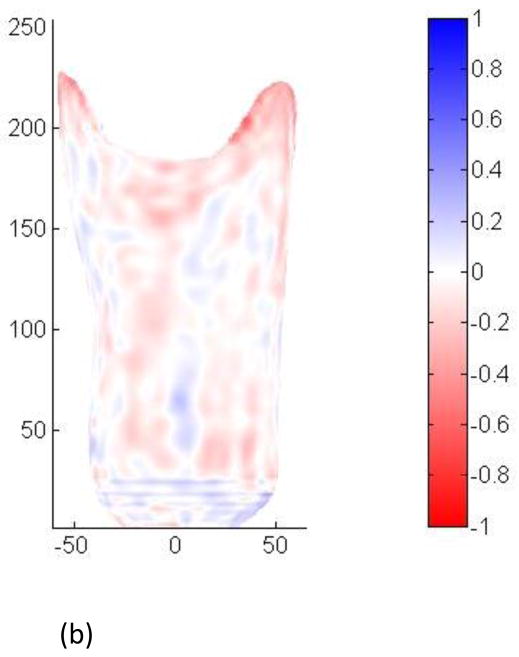
FIGURE 5a,b. Shape differences between inserts and digital surfaces.
(a) Measured right after insertion into the socket. (b) Measured after four weeks of wear. Scales are in mm.
No wear problems were evident during visual inspection of the inserts after regular use. No flaws in the adhesive at the junctions of the inserts were seen. None of the participants experienced injury wearing the sockets with inserts.
After 4 weeks of wear, sockets with inserts more closely matched the designed insert than when measured right after fabrication and installation (TABLE 3). Mean volume differences were −0.09% and mean radial error was −0.03mm. The distribution of shape difference was reasonably uniform over the surface (FIGURE 6b).
TABLE 3.
Fabricated Insert After 4 Weeks of Wear Compared with Designed Insert
| Participant | % Volume Difference | % within ±1 mm | min radial error (mm) | max radial error (mm) | mean radial error (mm) | st dev of radial error (mm) |
|---|---|---|---|---|---|---|
| 1 | −0.06 | 100.0 | −0.73 | 0.74 | −0.02 | 0.16 |
| 2 | −0.04 | 99.5 | −3.38 | 1.22 | −0.02 | 0.23 |
| 3 | −0.11 | 100.0 | −0.88 | 0.62 | −0.03 | 0.11 |
| 4 | −0.05 | 100.0 | −1.46 | 0.48 | −0.02 | 0.12 |
| 5 | −0.18 | 100.0 | −1.28 | 0.37 | −0.05 | 0.13 |
|
| ||||||
| MEAN | −0.09 | 99.9 | −1.54 | 0.69 | −0.03 | 0.15 |
DISCUSSION
In this study we demonstrated that high shape-quality computer manufactured plastic inserts can be manufactured for trans-tibial prosthesis users. They are an alternative to traditional insert fabrication that may offer advantages in clinical care. The versatility of CAD/CAM allows insert design to be easily modified or duplicated. Insert shape changes can be digitally tracked over time to monitor limb maturation.
The mechanical strength of printed polymers is less than that of prosthetic socket materials. Woven carbon fiber has a flexural strength of approximately 900 MPa [11], while 3-D printed materials have strengths of 40 to 120 MPa (according to manufacturer supplied data). However, because the prosthetic socket mechanically supported the insert, in our application the relatively low strength of the insert was not a complication.
As expected, insert shape quality improved after being worn by the amputee participant. With regular use the inserts settled into the sockets to be more flush against the inside socket surfaces and thus better matched the designed insert shapes. The mean decrease of 0.38% of the socket volume (−0.11mm mean radial error) for the newly placed insert vs. the designed insert shape corresponded roughly to approximately 55% of the thickness of a nylon sheath, or changing from a 6-ply to a 5-ply Soft Sock (SX) (Knit-Rite). The mean difference for the fabricated insert worn for 4 weeks compared with the designed insert shape of −0.09% of the socket volume (−0.03mm mean radial error) is approximately 15% of the thickness of a nylon sheath. These errors are small compared to computer socket manufacturing errors made using current CAD/CAM techniques. In a study evaluating computer manufactured sockets made by central fabrication facilities, only 3 of 33 sockets had mean radial errors within a range of −0.03mm to +0.03mm. Twenty-two of the 33 sockets had mean radial errors outside the range of −0.11mm to +0.11mm.
A next step towards implementing custom plastic inserts for use in clinical practice is to evaluate performance and clinical outcome over the long term. Do custom plastic inserts provide comparable or enhanced fit, comfort, and tissue health compared with traditional methods?
Design and fabrication time and cost must be reduced from that demonstrated here to bring the technology to clinical practice. Tabletop 3-D additive fabrication systems are relatively low cost to purchase and operate compared to socket fabrication systems and costs are expected to decrease in upcoming years. Thus rather than using out-of-house central fabrication, as is often done for computer manufactured sockets, practitioners may be able to place additive fabrication printers within their clinics to manufacture inserts. Further, insert fabrication is simplified for a practitioner already using computer socket manufacturing software to make the original socket since scanning of the original socket shape is unnecessary. The shape data is already available. Insert design requires only the practitioner’s computer and the tabletop 3-D fabrication system.
For custom plastic inserts to be effectively used in clinical practice, prosthetics design software would need to be enhanced from its present state to include solid model generation and manipulation as described in the Methods section of this paper. Current software packages make only surfaces, not 3-D models. Software needs to be designed so that the prosthetist easily proceeds through insert design and fabrication. The 100 minutes required here for scanning and design could be substantially reduced through software that automated the measurement and design processes described in the Methods section.
In addition to their potential clinical use to enhance socket design and fit, custom plastic inserts should have immediate research application in investigations testing the impact of socket shape changes and related variables on fit metrics, e.g. interface stresses, comfort, limb volume, and gait features. Inserts would simply be swapped out to effect socket shape changes, a methodology that is easier, faster, and more cost-effective than making multiple test sockets for each participant.
CONCLUSION
A method to design and fabricate custom plastic inserts for trans-tibial amputee prosthetic sockets was demonstrated. Insert shape was highly accurate and improved with wear as the inserts settled into the prosthetic sockets. After four weeks of use, inserts for the five participants tested here averaged less than a 0.09% absolute value volume difference (0.03mm mean radial error) compared with the designed shape.
Highlights.
A technique is described for computer manufacturing solid, plastic, socket inserts.
Inserts settled into the sockets over time the prosthesis was worn.
Fabrication quality after 4 weeks of use averaged less than 0.03 mm radial error.
Incorporating insert design into prosthetic software packages may be useful.
Acknowledgments
This research was funded by the National Institute of Child Health and Human Development at the National Institutes of Health, grant number R01HD069387.
Institutional review board approval was obtained from the University of Washington Human Subjects Division, study #37575.
Footnotes
There are no competing interests.
Publisher's Disclaimer: This is a PDF file of an unedited manuscript that has been accepted for publication. As a service to our customers we are providing this early version of the manuscript. The manuscript will undergo copyediting, typesetting, and review of the resulting proof before it is published in its final citable form. Please note that during the production process errors may be discovered which could affect the content, and all legal disclaimers that apply to the journal pertain.
Contributor Information
Joan E. Sanders, Email: jsanders@uw.edu.
Jake B. McLean, Email: jakemc@uw.edu.
John C. Cagle, Email: jcagle@uw.edu.
David W. Gardner, Email: davidg87@uw.edu.
Katheryn J. Allyn, Email: kate@allyn.org.
References
- 1.Saunders CG, Foort J, Bannon M, Lean D, Panych L. Computer aided design of prosthetic sockets for below-knee amputees. Prosthet Orthot Int. 1985 Apr;9(1):17–22. doi: 10.3109/03093648509164819. [DOI] [PubMed] [Google Scholar]
- 2.Holden JM, Fernie GR. Results of the pilot phase of a clinical evaluation of computer aided design of trans-tibial prosthesis sockets. Prosthet Orthot Int. 1986 Dec;10(3):142–8. doi: 10.3109/03093648609164519. [DOI] [PubMed] [Google Scholar]
- 3.Practice Analysis Task Force. Practice analysis of certified practitioners in the disciplines of orthotics and prosthetics. Alexandria (VA): American Board for Certification in Orthotics, Prosthetics, and Pedorthics, Inc; 2007. Available from: http://www.abcop.org/certification_/OrthotistsProsthetists/Documents_/PracticeAnalysis_SS04.pdf. [Google Scholar]
- 4.Faustini MC, Neptune RR, Crawford RH, Rogers WE, Bosker G. An experimental and theoretical framework for manufacturing prosthetic sockets for transtibial amputees. IEEE Trans Neural Syst Rehabil Eng. 2006 Sep;14(3):304–10. doi: 10.1109/TNSRE.2006.881570. [DOI] [PubMed] [Google Scholar]
- 5.Smith DG, Burgess Em. The use of CAD/CAM technology in prosthetics and orthotics - Current clinical models and a view to the future. J Rehabil Res Dev. 2001 May-Jun;38(3):327–334. [PubMed] [Google Scholar]
- 6.Ohtake Y, Belyaev A, Seidel H-P. An integrated approach to meshing scattered point data. Association for Computer Machinery Symposium on Solid and Physical Modeling (SPM 2005); June 2005; Cambridge, MA, USA: MIT; pp. 61–69. [Google Scholar]
- 7.Ohtake Y, Belyaev A, Seidel H-P. 3D scattered data approximation with adaptive compactly supported radial basis functions. International Conference on Shape Modeling and Applications (Shape Modeling International 2004); Genova, Italy. June 2004; pp. 31–39. [Google Scholar]
- 8.Sanders JE, Severance MR, Allyn KJ. Computer-socket manufacturing error: how much before it is clinically apparent? J Rehabil Res Dev. 2012;49(4):567–82. doi: 10.1682/jrrd.2011.05.0097. [DOI] [PMC free article] [PubMed] [Google Scholar]
- 9.Zachariah SG, Sorenson E, Sanders JE. A method for aligning trans-tibial residual limb shapes so as to identify regions of shape change. IEEE Trans Neural Systems Rehabil Eng. 2005;13(4):551–557. doi: 10.1109/TNSRE.2005.858459. [DOI] [PubMed] [Google Scholar]
- 10.Sanders JE, Cagle JC, Harrison DS, Karchin A. Amputee socks: how does sock ply relate to sock thickness? Prosthet Orthot Int. 2012;36(1):77–86. doi: 10.1177/0309364611431290. [DOI] [PMC free article] [PubMed] [Google Scholar]
- 11.Brocks T, Cioffi MO, Voorwalk HJ. Effect of fiber surface on flexural strength in carbon fabric reinforced epoxy composites. Applied Surface Science. 2013 Jun;274:210–16. [Google Scholar]


