Introduction
Trace elements, particularly metals, play an important role in a large variety of cellular processes in a biological system. In the context of biological organisms and tissues, the term trace element means that over the entire organism an element is present at only trace levels, say 100 ppm or lower. Trace element distribution and content can be analyzed using several techniques, for example, visible light optical fluorescence imaging, energy-dispersive x-ray spectroscopy on an electron microscope, synchrotron-based x-ray fluorescence (XRF) imaging, secondary-ion mass spectrometry, and laser ablation inductively coupled with mass spectrometry. Comprehensive reviews on these techniques are given by Lobinski et al. [1] and McRae et al. [2]. Among these techniques, synchrotron-based XRF microscopy, particularly utilizing third-generation x-ray sources and advanced x-ray focusing optics, offers the most suitable capabilities to perform trace element studies of biological samples: The penetrating power and non-destructive nature of x-rays allows one to image many-micron-thick biological samples such as biological whole cells in a way that visible light or electron microscopes cannot; the sensitivity of x-ray-induced XRF is down to parts per million, several orders of magnitude better than standard electron-based techniques due to the absence of bremsstrahlung background in x-ray-induced x-ray emission. The capability of imaging frozen samples in both 2D and 3D with sub-50 nm resolution in various x-ray modes has greatly advanced a broad range of scientific studies. This article describes how this technique can be used to track the incorporation of nanocomposites into cancer cells.
Materials and Methods
XRF analysis and elemental mapping
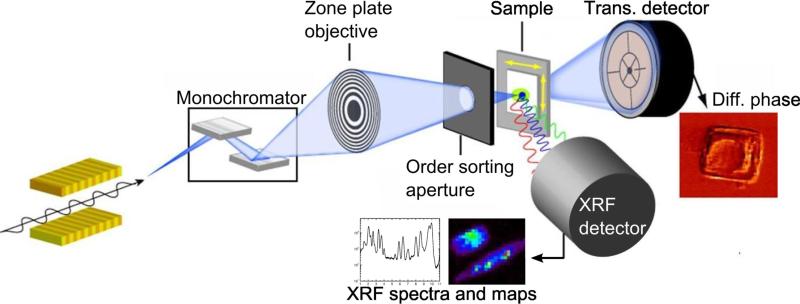
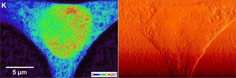
Two XRF microprobes are located at Sector 2 of the Advanced Photon Source (APS) at Argonne National Laboratory. They operate on a daily basis and provide a spatial resolution of ~250 nm. A typical setup of a synchrotron-based XRF micro/nanoprobe is shown in Figure 1. A monochromatized x-ray beam is focused using an x-ray objective lens (a Fresnel zone plate in this case) onto a sample. While the sample is raster-scanned, a full x-ray fluorescence spectrum is recorded for each pixel using an energy dispersive detector (Vortex-ME4, Hitachi High-Technologies Science America, USA) located at 90° with respect to the incident beam. This arrangement produces 2D elemental maps of the specimen. Simultaneously, a transmission signal is recorded using a quadrant photodiode for differential phase contrast imaging. Figure 2 shows both the potassium x-ray fluorescence map and a differential phase contrast image of a rat fibroblast cell. Quantitative information on the elemental concentration is obtained by comparing the fluorescence intensities with a calibration curve derived from measurements of a thin-film XRF standard (RF8-200-S2453, AXO DRESDEN GmbH, Germany).
Figure 1.
Schematic of a synchrotron-based x-ray fluorescence micro/nanoprobe. A monochromatized x-ray beam is focused onto the sample using a zone plate. While the sample is raster scanned, x-ray fluorescence spectra are recorded, forming 2D elemental maps and 3D reconstructions in tomography mode. Differential phase contrast images are produced from transmission signals recorded using a quadrant photodiode. This figure was adapted from Figure 6 of [3].
Figure 2.
Potassium (K) x-ray fluorescence image (left side) and a differential phase contrast image (right side) of a rat fibroblast cell. The count level for K signal (minimum to maximum range) is 0-267 counts/s. The images were acquired with the Bionanoprobe using a 50 nm step size.
Bionanoprobe
Challenges arise in both instrumentation and sample preparation: How can an incident x-ray beam be produced sufficiently small and stable to probe individual organelles? How to preserve both the structure and chemistry of samples as in their natural states? How to prevent damage of a sample under intense x-rays and repeated imaging? To overcome these challenges, we developed the Bionanoprobe (BNP), an x-ray microscope with a sub-50 nm x-ray probe size, tomography capabilities, and a cryogenic sample environment.
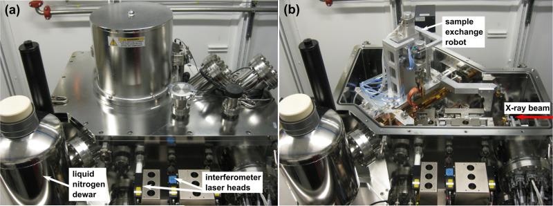
The BNP is housed at an undulator beamline of the Life Sciences Collaboration Access Team at the APS, where the incident x-ray energy (E) is in the range of 4.5 – 35 keV with an energy resolution (ΔE/E) of 2×10⁻⁴. The BNP is dedicated to the studies of trace elements within frozen biological samples and other materials at sub-50 nm spatial resolution. It operates under high vacuum (10−7-10−8 torr) and cryogenic (<110 K) conditions (Figure 3). Samples are conductively cooled using liquid nitrogen. The vacuum condition protects frozen samples from frosting and minimizes air absorption of low-energy fluorescence x rays. The motion of the scanning stages is precisely controlled using laser interferometer systems. Using the BNP at an incident photon energy of 10 keV, we have observed 25 nm features on a resolution test pattern [6]. The practical spatial resolution of analysis is about an order of magnitude better than the other existing microprobes.
Figure 3.
Components of the Bionanoprobe: (a) liquid nitrogen dewar attached to the vacuum chamber. Liquid nitrogen provides conductive cooling to components holding the specimen inside the chamber. A laser interferometer system is used for precise stage positioning. (b) robot used for sample exchange inside the chamber. This figure was adapted from Figure 1 of [6].
Biological samples have been studied in the frozen-hydrated state at a temperature below 110 K. A robotic sample loading mechanism is used to transfer samples onto the sample stage under cryogenic conditions. The ability to perform cryogenic experiments has greatly advanced x-ray fluorescence studies, particularly for organic samples, such as biological cells and tissues. Biological cells typically contain more than 90% of water. By fast freezing, cellular water is retained as amorphous ice, and the cellular structure and ionic distributions are more faithfully preserved in their natural states compared to samples prepared by dehydration methods. In addition, the radiation resistance of organic materials is improved at low temperatures [7].
Tomography
However, difficulties arise in accurately interpreting 2D images, particularly those collected from thick samples, such as cryogenically fixed biological whole cells, because of the lack of information at various depths. X-ray fluorescence tomography is highly desired in this case. The BNP employs a rotation sample stage with a vertical rotation axis, enabling a total rotation of 180°. Typically, about sixty 2D projections are collected with an estimated accumulated dose of 1010 gray. No radiation damage to cryogenic samples has been observed at spatial resolutions of 100 nm and above. The quality of tomogram reconstruction is improved by projection image alignment, rotation axis correction, and background subtraction. Recently, XRF tomography has been developed and used to study 3D elemental distributions in biological samples on a sub-cellular level [3, 4].
Results
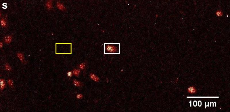
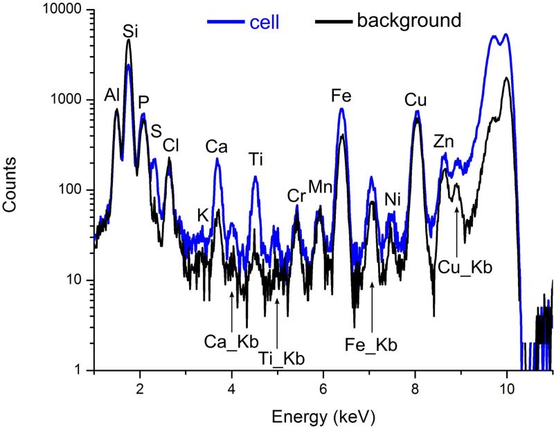
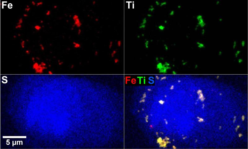
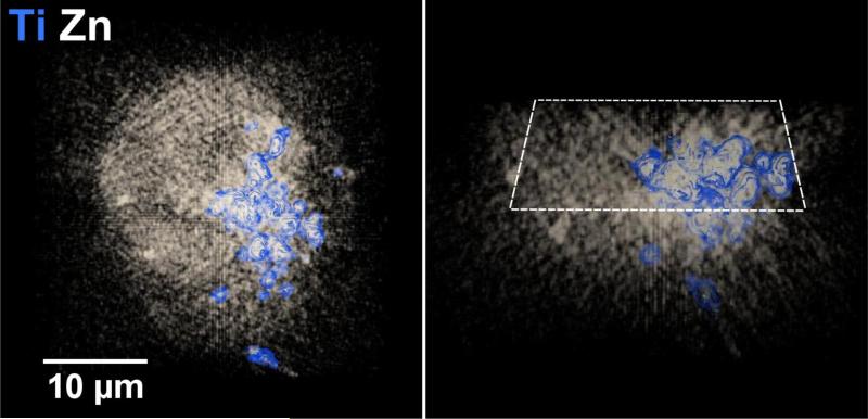
The Bionanoprobe has been employed to study nuclear DNA targeting using photoactive nanocomposites. Different approaches have been developed to deliver nanoparticles composed of photoactivatable materials (such as TiO2) to the nuclei of cancer cells where these nanoparticles can cleave nuclear DNA under photoactivation. We have synthesized 6-7 nm nanoparticles consisting of a Fe3O4 core and a TiO2 shell (Fe3O4@TiO2) and surface-conjugated these with several different peptides to facilitate nuclear delivery [5]. Cultured HeLa cervical cancer cells were used for this study. This cell line is the most understood and the most commonly used human cell line in scientific research. We then used the BNP to examine the nanocomposite-treated HeLa cell, and determined the distribution of these nanocomposites. A particular question to answer is whether the nanocomposites would reach the nucleus after cellular internalization. We chose incident photon energy of 10 keV, which allows excitation of Kα x-ray fluorescence in elements with atomic numbers up to 30 (Zn). Distributions of both natural cellular elements (S and Zn for example) and the elements introduced with the nanocomposites (Fe and Ti) were detected within a HeLa cell of about 20 |im in diameter. In a low-magnification survey map (Figure 4), the S fluorescence signal was used to locate cells of interest since S is present in the amino acids methionine and cysteine and is therefore distributed throughout the cell [5]. Figure 5 shows x-ray spectra from a cell (white box in Figure 4) and a background region of the same area (yellow box in Figure 4). These spectra show that cells exhibit elevated levels of S, Ca, Ti, and Fe compared a sample region devoid of cells (background spectrum). Figure 6 shows the colocalization of Fe, Ti, and S signals in higher magnification maps acquired using a 50 nm step size. These elemental maps demonstrate that some of the nanocomposites were possibly translocated into the cell. Multiple cells were examined using the same method. To confirm that nanocomposites were located within the nucleus rather than on the cell outer surface, a 3D tomographic reconstruction was produced (Figure 7). The elevated Zn fluorescence signal, probably from Zn fingers, is an indicator of the nuclear region [5]. This 3D rendering shows the Ti hot spots inside the Zn-rich volume, and therefore confirms the success of nuclear delivery of the nanocomposites. Results from several of these x-ray 2D maps and 3D renderings indicate that about 20% of the nanocomposites were translocated into the nucleus [5].
Figure 4.
An survey scan acquired using an 850 nm step size of a frozen-hydrated HeLa cell sample treated with Fe3O4@TiO2 nanocomposites for 30 min. Cells were identified using the S fluorescence signal. The white box indicates the cell examined in Figures 5 and 6. The yellow box shows where the background signal was acquired. This figure was adapted from Figure 9 of [6].
Figure 5.
X-ray fluorescence spectra, from the cell and a background region of Figure 4. The elements S, Ca, Ti, and Fe exhibit signals above background within the cell.
Figure 6.
Elemental x-ray maps of the cell in Figure 4 acquired using a 50 nm step size. These maps show the distribution of the nanocomposites (identified by the Fe and Ti signals) with respect to cellular structures. This figure was adapted from Figure 9 of [6].
Figure 7.
Three-dimensional reconstruction (side view on left; cross section on right) of a frozen-hydrated HeLa cancer cell treated with Fe3O4@TiO2 nanocomposites for 30 min showing that some of the nanocomposites (identified by the Ti signals) were successfully delivered into the nuclear region (identified by elevated Zn signals). The 3D volume reconstruction was based on 53 projections with an angular coverage from −78° to 78° and an angular step size of 3°. Each projection was acquired using a 250 nm step size. This figure was adapted from Figure 6 of [8].
Conclusion
The Bionanoprobe is a new facility at the Advanced Photon Source of Argonne National Laboratory. This beam-line setup allows fluorescence x-ray mapping of elements in biological organisms and cells at sub-micrometer spatial resolution. Elements that appear in trace amounts over the whole organism or cell can be imaged in x-ray maps as segregated to cells and cell organelles.
Acknowledgment
This research used resources of the Advanced Photon Source, a U.S. Department of Energy (DOE) Office of Science User Facility operated for the DOE Office of Science by Argonne National Laboratory under Contract No. DE-AC02-06CH11357. We thank the National Institutes of Health for supporting the acquisition of the Bionanoprobe (BNP) under ARRA grant SP0007167, and for cryogenic sample preparation and ptychography development under grant R01 GM104530.
References
- 1.Lobinski R, Moulin C, Ortega R. Biochimie. 2006;88(11):1591–604. doi: 10.1016/j.biochi.2006.10.003. [DOI] [PubMed] [Google Scholar]
- 2.McRae R, Bagchi P, Sumalekshmy S, Fahrni CJ. Chemical Reviews. 2009;109(10):4780–827. doi: 10.1021/cr900223a. [DOI] [PMC free article] [PubMed] [Google Scholar]
- 3.Jonge M de, Holzner C, Baines SB, Twining BS, Ignatyev K, Diaz J, Howard DL, Legnini D, Miceli A, McNulty I, Jacobsen C, Vogt S. Proceedings of the National Academy of Sciences. 2010;107(36):15676–80. doi: 10.1073/pnas.1001469107. [DOI] [PMC free article] [PubMed] [Google Scholar]
- 4.Que E, Bleher R, Duncan FE, Kong BY, Gleber SC, Vogt S, Chen S, Garwin S, Bayer AR, David VP, Woodruff TK, O'Halloran TV. Nature Chemistry Published online. 2014 doi: 10.1038/nchem.2133. DOI: 10.1038/NCHEM.2133. [DOI] [PMC free article] [PubMed] [Google Scholar]
- 5.Yuan Y, Chen S, Paunesku T, Gleber SC, Liu WC, Doty CB, Mak R, Deng J, Jin Q, Lai B, Brister K, Flachenecker C, Jacobsen C, Vogt S, Woloschak GE. ACS Nano. 2013;7(12):10502–17. doi: 10.1021/nn4033294. [DOI] [PMC free article] [PubMed] [Google Scholar]
- 6.Chen S, Deng J, Yuan Y, Flachenecker C, Mak R, Hornberger B, Jin Q, Shu D, Lai B, Maser J, Roehrig C, Paunesku T, Gleber SC, Vine DJ, Finney L, VonOsinski J, Bolbat M, Spink I, Chen Z, Steel J, Trapp D, Irwin J, Feser M, Snyder E, Brister K, Jacobsen C, Woloschak G, Vogt S. Journal of Synchrotron Radiation. 2014;21:66–75. doi: 10.1107/S1600577513029676. [DOI] [PMC free article] [PubMed] [Google Scholar]
- 7.Maser J, Osanna A, Wang Y, Jacobsen C, Kirz J, Spector S, Winn B, Tennant D. Journal of Microscopy. 2000;197:68–79. doi: 10.1046/j.1365-2818.2000.00630.x. [DOI] [PubMed] [Google Scholar]
- 8.Chen S, Yuan Y, Deng J, Mak R, Jin Q, Paunesku T, Gleber SC, Vine D, Flachenecker C, Hornberger B, Shu D, Lai B, Maser J, Finney L, Roehrig C, VonOsinski J, Bolbat M, Brister K, Jacobsen C, Woloschak G, Vogt S. Proc. SPIE 8851, X-ray Nanoimaging: Instruments and Methods. :885102. [Google Scholar]


