Abstract
A novel method for integrating and embedding objects to add new functionalities during 3D printing based on fused deposition modeling (FDM) (also known as fused filament fabrication or molten polymer deposition) is presented. Unlike typical 3D printing, FDM-based 3D printing could allow objects to be integrated and embedded during 3D printing and the FDM-based 3D printed devices do not typically require any post-processing and finishing. Thus, various fluidic devices with integrated glass cover slips or polystyrene films with and without an embedded porous membrane, and optical devices with embedded Corning® Fibrance™ Light-Diffusing Fiber were 3D printed to demonstrate the versatility of the FDM-based 3D printing and embedding method. Fluid perfusion flow experiments with a blue colored food dye solution were used to visually confirm fluid flow and/or fluid perfusion through the embedded porous membrane in the 3D printed fluidic devices. Similar to typical 3D printed devices, FDM-based 3D printed devices are translucent at best unless post-polishing is performed and optical transparency is highly desirable in any fluidic devices; integrated glass cover slips or polystyrene films would provide a perfect optical transparent window for observation and visualization. In addition, they also provide a compatible flat smooth surface for biological or biomolecular applications. The 3D printed fluidic devices with an embedded porous membrane are applicable to biological or chemical applications such as continuous perfusion cell culture or biocatalytic synthesis but without the need for any post-device assembly and finishing. The 3D printed devices with embedded Corning® Fibrance™ Light-Diffusing Fiber would have applications in display, illumination, or optical applications. Furthermore, the FDM-based 3D printing and embedding method could also be utilized to print casting molds with an integrated glass bottom for polydimethylsiloxane (PDMS) device replication. These 3D printed glass bottom casting molds would result in PDMS replicas with a flat smooth bottom surface for better bonding and adhesion.
I. INTRODUCTION
Additive manufacturing or 3D printing is a process for building a 3D object/part from a 3D model generated by a computer-aided design (CAD) program through additive processes in which successive layers of material are laid down under computer control. 3D printing has traditionally been used in manufacturing industries to produce design prototypes, but recently, it has gained popularity in being used to fabricate microfluidic devices due to its ability to make complex structures with high resolution.1–5 Also, device designs can be easily generated, modified, and shared using CAD programs, and then conveniently ordered using a 3D printing mail-order service with device cost precisely predicted via a web interface.6 For example, applications in the areas of electrochemical detection,7,8 reconfigurable modular systems,9–12 microfluidic automation and valving,13–15 pathogenic bacteria detection,16,17 drug transport and cell viability,18 and chemical syntheses19 have been demonstrated with 3D printed microfluidic or millifluidic devices. Also, 3D printing has been used to fabricate molds for casting polydimethylsiloxane (PDMS) microfluidic devices.20,21 In addition, with a proper device design, accessories can be assembled to the 3D printed devices after they are built/printed so that additional functions can be added to the 3D printed devices.7,18,22–24 Furthermore, direct multi-material 3D printing using different polymers, e.g., soft and rigid polymers, from a 3D CAD model has also been demonstrated.25
Clearly, the unique method of printing 3D structures could have huge potential and competitive advantages over the traditional fabrication or manufacturing processes. In addition to the ability to print 3D structures with multi-materials, the other attractive advantage of 3D printing is that objects could be embedded during 3D printing using a photopolymer.26–28 Since no additional bonding/sealing process is needed, the photopolymer-based 3D printed objects would completely eliminate any post-packing and assembly steps even though post-finishing steps are still required. For example, Ikuta et al. presented a micro concentrator chip with an embedded ultrafiltration membrane and built-in photodiode.26 The micro concentrator chip was 3D printed by micro stereolithography (SLA). In this micro SLA process, the micro concentrator chip was printed layer by layer from a photo curable liquid polymer using a focused ultra-violet (UV) beam. The ultrafiltration membrane was inserted during the micro SLA process. After the micro concentrator chip with the embedded ultrafiltration membrane was 3D printed, the liquid (non-cross linked) polymer where no UV beam was irradiated was washed out by rinsing. However, embedding objects using a photopolymer during 3D printing has its shortcomings. In the case of Ikuta et al., since the ultrafiltration membrane was immersed into the liquid polymer during the micro SLA process, it would be problematic to completely wash out the non-cross linked liquid polymer in the ultrafiltration membrane at the end of the micro SLA process. This leftover liquid polymer could affect the performance of the ultrafiltration membrane and hence the micro concentrator chip. Also, after an object is 3D printed using a photopolymer, a final finishing step is typically required to manually finish the object. This includes removal and sanding down the support structures used in the printing process and a final UV post-curve to ensure that the object achieves its best mechanical properties. In addition, in order to achieve optical clarity with the object, the whole object would have to be finely sand blasted and/or polished.
Since the ability to integrate or embed objects during 3D printing to create a 3D object has not been fully explored and developed, in this article, a novel method for integrating and embedding objects to add new functionalities during 3D printing based on fused deposition modeling (FDM) (also known as fused filament fabrication (FFF) or molten polymer deposition (MPD)) is presented. Various fluidic devices with integrated glass cover slips or polystyrene films with and without an embedded porous membrane, and optical devices with embedded Corning® Fibrance™ Light-Diffusing Fiber (Corning Incorporated, Corning, NY, USA) as well as a casting mold with an integrated glass bottom for PDMS device replication were 3D printed to demonstrate the versatility of the FDM-based 3D printing and embedding method. The 3D printed fluidic devices with an embedded porous membrane are applicable to biological or chemical applications such as continuous perfusion cell culture29 or biocatalytic synthesis30 but without the need for any post-device assembly and finishing. The 3D printed optical devices with embedded Corning® Fibrance™ Light-Diffusing Fiber would have applications in display, illumination, or optical applications.28 The 3D printed glass bottom casting mold would result in PDMS replicas with a flat smooth bottom surface for better bonding and adhesion.
II. EXPERIMENTAL DETAILS
A. Fused deposition modeling (FDM)
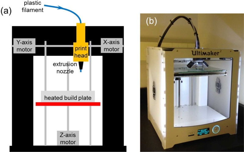
Unlike 3D printers that use photopolymers, FDM-based 3D printers build a 3D object by heating a thermoplastic filament, typically 2.85 mm or 1.7 mm in diameter, to a semi-molten state, extruding the semi-molten filament through an extrusion nozzle of the print head and depositing it layer by layer based on the 3D CAD model onto an adjustable heated build plate (Fig. 1(a)). FDM is probably the most popular 3D printing method today due to the number of FDM-based 3D printers available on the market and their low price. Unlike typical 3D printing, FDM-based 3D printing could allow objects to be integrated and embedded during 3D printing and the 3D printed devices do not typically require any post-processing and finishing. Some FDM-based 3D printers have two or more print heads to print in multiple colors and use support for overhanging areas of a complex 3D print. Today, there are numerous materials that support FDM-based 3D printers, which make them ideal for the consumer market. The most common materials used in FDM-based 3D printers are polylactic acid (PLA) and acrylonitrile butadiene styrene (ABS). PLA plastic is bio-degradable and is manufactured out of plant-based materials such as corn starch or sugar cane. ABS plastic is manufactured out of oil-based materials and has a much higher melting point than PLA plastic. ABS plastic is also stronger and harder. Other materials such as polyvinyl alcohol (PVA), high impact polystyrene (HIPS), and flexible materials like thermoplastic elastomer (TPE) are also available for FDM-based 3D printers.
FIG. 1.
(a) Schematic diagram of a FDM-based 3D printer. (b) Image of the Ultimaker 2 used in this study.
B. 3D CAD model and printing
Each 3D device design was first designed, generated, and exported to a stereolithography (STL) file using AutoDesk® AutoCAD® Mechanical 2014 Software (Autodesk, Inc., San Rafael, CA, USA). The STL file was then loaded to Cura 3D Printing Slicing Software (Version 14.09, Ultimaker B.V., Geldermalsen, The Netherlands) and saved as a GCode file into a SDHC card (SanDisk Corporation, Milpitas, CA, USA). Finally, the SDHC card was inserted into the Ultimaker 2 (Ultimaker B.V.) (Fig. 1(b)), which has a 0.4 mm diameter extrusion nozzle, to 3D print each device using the GCode files. As recommended by the Ultimaker 2 manufacturer, before 3D printing each device, a glue stick (Staples® Washable Glue Sticks, Staples, Inc., Framingham, MA, USA) was used to apply a thin layer of glue on the adjustable heated glass build plate so that the printed 3D device could be easily removed from the heated glass build plate. Alternatively, if a flat smooth glossy bottom device surface is desired, a Kapton polyimide adhesive tape (2 mil (∼50 μm) thick Nulink™ Kapton Polyimide Heat High Temperature Resistant Adhesive Gold Tape, Amazon.com, Inc., Seattle, WA, USA) could be used on the adjustable heated glass build plate instead of the glue. Natural/Transparent 2.85 mm diameter colorFabb XT Copolyester Filament (colorFabb, Venlo, The Netherlands), which is a styrene free, FDA food contact compliant and BPA (bisphenol A) free formulation, was used to 3D print devices at a printing temperature between 240 °C and 260 °C according to the specifications of the colorFabb XT Copolyester Filament and the default setting of the Ultimaker 2. Also, the support structure was not used during 3D printing to eliminate the need for post-finishing the printed 3D device. During each print, the 3D printing process was temporarily paused at the specific Z-height(s) according to each 3D device design in order to integrate or embed the required object(s). In addition, tiny drops of a bio-compatible glue (Bio-PSA 7-4301 Silicone Adhesive, Dow Corning, Midland, MI, USA) were used to fix the object onto the printed structure so that the object would not be moved or damaged by the extrusion nozzle of the print head when the 3D printing process was resumed.
III. RESULTS AND DISCUSSION
A. Proof-of-concept devices and testing
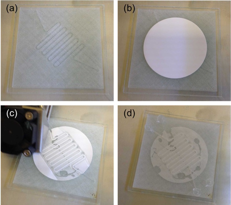
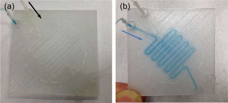
Various fluidic and optical devices were 3D printed using the Ultimaker 2 to demonstrate the versatility of the FDM-based 3D printing and embedding method. In the first 3D printed perfusion fluidic device, a 5 μm pore size cellular acetate membrane (Order No. 12342-47-K, Sartorius Stedim Biotech GmbH, Göttingen, Germany) was embedded between the top and the bottom open serpentine channels (Figs. 2 and 3). Other porous membranes such as polyester, polytetrafluoroethylene (PTFE), or nylon membranes that could survive the extrusion temperature of the thermoplastic filament during the 3D printing process could also be used. A fluid perfusion flow experiment with a blue colored food dye solution was used to visually confirm the perfusion functionality of the embedded cellular acetate membrane in the first 3D printed perfusion fluidic device (Fig. 4). The blue colored food dye solution was diffusing from the bottom serpentine channel through the embedded cellular acetate membrane and into the top serpentine channel, and it was confined within the top and the bottom serpentine channels. This simple colored food dye perfusion experiment demonstrated that the perfusion functionality of the cellular acetate membrane was retained after 3D printing; demonstrating the feasibility of using the FDM-based 3D printing and embedding method to fabricate porous membrane-based microfluidic devices. The first 3D printed perfusion fluidic device is applicable to continuous microcarrier-based cell culture or biocatalytic synthesis applications similar to the one described by Abeille et al.29 and O'Sullivan et al.,30 respectively, but without the need for any post-device assembly and finishing.
FIG. 2.
(a) 3D CAD model of the first perfusion fluidic device without the porous membrane. (b) Schematic diagram of the exploded cross-sectional view of Section A–A depicted in (a) with the porous membrane separating the top and the bottom open serpentine channels.
FIG. 3.
3D printing sequence of the first perfusion fluidic device with an embedded 5 μm pore size cellular acetate membrane depicted in Fig. 2(b). (a) The bottom open serpentine channel was first 3D printed. (b) The cellular acetate membrane was then glued down on top of the bottom open serpentine channel. (c) 3D printing resumed after gluing down the cellular acetate membrane. (d) 3D printing completed with the cellular acetate membrane embedded between the top and the bottom open serpentine channels. Serpentine channel cross-sectional dimensions were 1 mm × 1 mm.
FIG. 4.
Fluid perfusion flow experiment for testing the first 3D printed perfusion fluidic device with the embedded 5 μm pore size cellular acetate membrane depicted in Fig. 3(d). (a) Device priming with water flowing inside the top serpentine channel. (b) A blue colored food dye solution was flowing inside the bottom serpentine channel and diffusing through the cellular acetate membrane and into the top serpentine channel. The black and blue arrows indicate the flow direction. Flow rates were 100 μl/min.
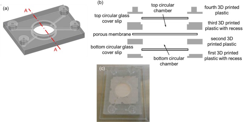
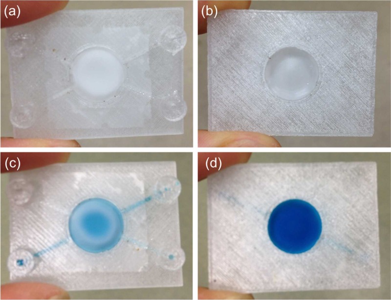
Similar to typical 3D printed devices, FDM-based 3D printed devices are translucent at best unless post-polishing is performed and optical transparency is highly desirable in any fluidic devices; in the second 3D printed perfusion fluidic device, in addition to the 1.2 μm pore size cellular acetate membrane (Whatman® ST 69, Catalog No. 10403012, Whatman GmbH, Dassel, Germany), two 15 mm diameter no. 1 (0.13 mm to 0.17 mm thick) glass cover slips (Catalog No. 22-031-144, Fisherbrand™ Cover Glasses, Fisher Scientific, Pittsburgh, PA, USA) were integrated during 3D printing (Fig. 5). Both circular glass cover slips would provide a perfect optical transparent window for observation and visualization as well as a compatible flat smooth surface for biological or biomolecular applications. Because of the thickness of the circular glass cover slips, recesses were incorporated into the 3D CAD model to allow the circular glass cover slips to sit flush with the 3D printed structure to avoid damaged by the extrusion nozzle of the print head when 3D printing was resumed (Fig. 5(b)). Similar to the first 3D printed perfusion fluidic device, a fluid perfusion experiment with the blue colored food dye solution was used to visually confirm that the perfusion functionality of the embedded cellular acetate membrane was retained in the second 3D printed perfusion fluidic device after the 3D printing process (Fig. 6). The blue colored food dye solution in the bottom circular chamber was gradually diffusing into the top circular chamber through the embedded cellular acetate membrane and it was confined within the top and the bottom circular chambers.
FIG. 5.
(a) 3D CAD model of the second perfusion fluidic device without the porous membrane, and the top and the bottom circular glass cover slips. (b) Schematic diagram of the exploded cross-sectional view of Section A–A depicted in (a) with the porous membrane separating the top and the bottom circular chambers. The top and the bottom circular glass cover slips were used as the top and the bottom surfaces of the top and the bottom circular chambers, respectively. (c) Second 3D printed perfusion fluidic device with the embedded 1.2 μm pore size cellular acetate membrane separating the top and the bottom circular chambers, and the integrated top and bottom circular glass cover slips. Channel cross-sectional dimensions were 1 mm × 1 mm and the two circular chambers were both 1 mm tall and 13 mm in diameter.
FIG. 6.
Fluid perfusion experiment for testing the second 3D printed perfusion fluidic device with the embedded 1.2 μm pore size cellular acetate membrane separating the top and the bottom circular chambers, and the integrated top and bottom 15 mm diameter no. 1 circular glass cover slips depicted in Fig. 5(c). (a) Top and (b) bottom views of the device after water were pipetted inside the top and the bottom circular chambers. (c) Top and (d) bottom views of the device after a blue colored food dye solution was pipetted inside the bottom circular chamber. The blue colored food dye solution was gradually diffusing through the cellular acetate membrane and into the top circular chamber from the bottom circular chamber.
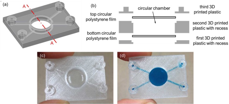
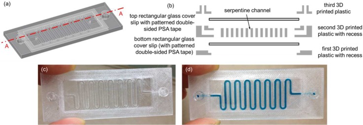
The third 3D printed fluidic device was exactly the same as the second 3D printed perfusion fluidic device except that the cellular acetate membrane was not embedded and two 15 mm diameter 3 mil (∼75 μm) thick polystyrene films were integrated instead of the two circular glass cover slips during 3D printing (Figs. 7(a)–7(c)). Similar to the previous fluidic experiments, the blue colored food dye solution was used to visually confirm that there was no fluid leakage in the third 3D printed fluidic device (Fig. 7(d)). In the fourth 3D printed fluidic device, two 24 mm × 60 mm no. 1 (0.13 mm to 0.17 mm thick) rectangular glass cover slips (Catalog No. 12-548-5 P, Fisherfinest™ Premium Cover Glass, Fisher Scientific, Pittsburgh, PA, USA) were integrated during 3D printing to form the top and the bottom surfaces of a serpentine channel (Figs. 8(a)–8(c)). Again, the blue colored food dye solution was used to visually confirm that there was no fluid leakage in the fourth 3D printed fluidic device (Fig. 8(d)). In this case, in order to create a fluid leak-free interface between the top rectangular glass cover slip and the top surface of the 3D printed serpentine structure, a patterned 1.9 mil (∼50 μm) thick double-sided pressure sensitive adhesive (PSA) tape (ARcare® 92712; Adhesive Research, Inc., Glen Rock, PA, USA) was used to adhere the two together before resuming the 3D printing process. The PSA tape was patterned by a desktop digital craft cutter.31 The patterned PSA tape could also be used on the bottom rectangular glass cover slip before resuming the 3D printing process in case the semi-molten filament fails to adhere to the bottom rectangular glass cover slip. Glass surface treatments such as using silanes as adhesion promoters to enhance the interface adhesion between the bottom rectangular glass cover slip and the semi-molten filament would be an interesting research area to explore in future studies. Two additional exemplary 3D printed fluidic devices can be found in the supplementary material (Figs. S1 and S2).
FIG. 7.
(a) 3D CAD model of the third fluidic device without the top and the bottom circular polystyrene films. (b) Schematic diagram of the exploded cross-sectional view of Section A–A depicted in (a) with the top and the bottom circular polystyrene films. (c) Third 3D printed fluidic device with the integrated top and bottom 15 mm diameter 3 mil (∼75 μm) thick polystyrene films creating a circular chamber between them. (d) A blue colored food dye solution was pipetted inside the circular chamber. Channel cross-sectional dimensions were 1 mm × 1 mm and the circular chamber was 2 mm tall and 13 mm in diameter.
FIG. 8.
(a) 3D CAD model of the fourth fluidic device without the top and the bottom rectangular glass cover slips. (b) Schematic diagram of the exploded cross-sectional view of Section A–A depicted in (a) with the top and the bottom rectangular glass cover slips. (c) 3D printed fluidic device with the integrated top and bottom 24 mm × 60 mm no.1 rectangular glass cover slips. (d) A blue colored food dye solution was pipetted inside the serpentine channel. Serpentine cross-sectional dimensions were 1 mm wide × 2 mm tall.
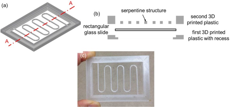
Since using 3D printing to fabricate molds for casting PDMS microfluidic devices is getting popular in the microfluidic community,19,20 the FDM-based 3D printing and embedding method could also be utilized to 3D print PDMS casting molds with an integrated glass bottom. These glass bottom PDMS molds would result in PDMS replicas with a flat smooth bottom surface for better bonding and adhesion. For example, a serpentine channel mold with an integrated 75 mm × 50 mm and 0.96 mm to 1.06 mm thick rectangular glass slide (Corning® 2947-75 × 50, Corning Incorporated, Corning, NY, USA) as the mold bottom for casting PDMS fluidic devices was 3D printed (Fig. 9).
FIG. 9.
(a) 3D CAD model of a serpentine channel mold without the bottom rectangular glass slide. (b) Schematic diagram of the exploded cross-sectional view of Section A–A depicted in (a) with the bottom rectangular glass slide. (c) 3D printed serpentine channel mold with the integrated bottom 75 mm × 50 mm and 0.96 mm to 1.06 mm thick rectangular glass slide. The cross-sectional dimensions of the serpentine structure were 1 mm × 1 mm.
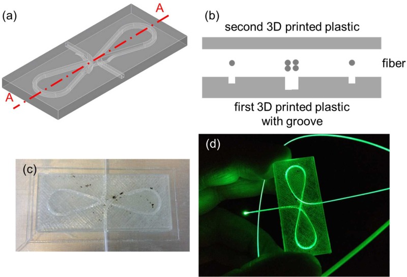
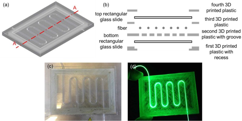
Finally, two 3D printed optical devices were demonstrated by embedding the Corning® Fibrance™ Light-Diffusing Fiber into the devices during 3D printing (Figs. 10 and 11). In both cases, a groove was incorporated into the 3D CAD models to allow the fiber to be inserted and sit flush with the 3D printed structure before resuming the 3D printing process. The first optical device was 3D printed with the Corning® Fibrance™ Light-Diffusing Fiber embedded during 3D printing (Figs. 10(a)–10(c)). The first 3D printed optical device was tested with a green laser pointer to visually confirm that the light diffusing functionality of the Corning® Fibrance™ Light-Diffusing Fiber was not affected after the 3D printing process (Fig. 10(d)). Also, the embedded fiber could be looped and crossed over itself at different heights and it is not limited to one planar surface. Similar exemplary 3D printed optical device can be found in the supplementary material (Fig. S3). The second 3D printed optical device was demonstrated by integrating two 75 mm × 50 mm and 0.96 mm to 1.06 mm thick rectangular glass slides that sandwiched the embedded Corning® Fibrance™ Light-Diffusing Fiber (Fig. 11). The second 3D printed optical device design is important when glass is desired as the optical panel instead of the 3D printed plastic, e.g., for better light transmission and optical clarity.
FIG. 10.
(a) 3D CAD model of the first optical device without the fiber. (b) Schematic diagram of the exploded cross-sectional view of Section A–A depicted in (a) with the fiber. The first 3D printed optical device with embedded Corning® Fibrance™ Light-Diffusing Fiber (c) was not and (d) was lit up using a green laser pointer.
FIG. 11.
(a) 3D CAD model of the second optical device without the fiber, and the top and the bottom rectangular glass slides. (b) Schematic diagram of the exploded cross-sectional view of Section A–A depicted in (a) with the fiber, and the top and the bottom rectangular glass slides. (c) The second 3D printed optical device with embedded Corning® Fibrance™ Light-Diffusing Fiber, and the integrated top and bottom 75 mm × 50 mm and 0.96 mm to 1.06 mm thick rectangular glass slides. (d) The device was lit up using a green laser pointer.
IV. CONCLUSIONS
Using FDM-based 3D printers, 3D CAD models could be designed to allow various objects with different shapes to be integrated and/or embedded during 3D printing in order to add new functionalities to the 3D printed models. Several fluidic and optical devices with integrated and/or embedded objects as well as an example of a glass bottom casting mold for PDMS device replication were 3D printed and their functionalities were also demonstrated to show that each integrated/embedded object was not affected by the 3D printing process. It is worth pointing out that in addition to the material shrinkage during 3D printing (>10% with ABS in the current study) and the layer resolution and the position precision of the FDM-based 3D printer, the extrusion nozzle diameter of the FDM-based 3D printer also has a huge impact on the resolutions of the 3D printed devices. It is expected that the 3D printed devices would not have any feature sizes smaller than the extrusion nozzle diameter. Thus, using a smaller extrusion nozzle diameter in the FDM-based 3D printer would help improve the resolutions of the 3D printed devices.
V. SUPPLEMENTARY MATERIAL
See supplementary material for three additional exemplary 3D printed devices.
References
- 1. Bhattacharjee N., Urrios A., Kanga S., and Folch A., “ The upcoming 3D-printing revolution in microfluidics,” Lab Chip (16), 1720–1742. 10.1039/C6LC00163G [DOI] [PMC free article] [PubMed] [Google Scholar]
- 2. Ho C. M. B., Ng S. H., Lia K. H. H., and Yoon Y.-J., “ 3D printed microfluidics for biological applications,” Lab Chip , 3627–3637 (2015). 10.1039/C5LC00685F [DOI] [PubMed] [Google Scholar]
- 3. Gross B. C., Erkal J. L., Lockwood S. Y., Chen C., and Spence D. M., “ Evaluation of 3D printing and its potential impact on biotechnology and the chemical sciences,” Anal. Chem. , 3240–3253 (2014). 10.1021/ac403397r [DOI] [PubMed] [Google Scholar]
- 4. O'Neill P. F., Ben Azouz A., Vázquez M., Liu J., Marczak S., Slouka Z., Chang H. C., Diamond D., and Brabazon D., “ Advances in three-dimensional rapid prototyping of microfluidic devices for biological applications,” Biomicrofluidics , 052112 (2014). 10.1063/1.4898632 [DOI] [PMC free article] [PubMed] [Google Scholar]
- 5. Waldbaur A., Rapp H., Länge K., and Rapp B. E., “ Let there be chip–towards rapid prototyping of microfluidic devices: One-step manufacturing processes,” Anal. Methods , 2681–2716 (2011). 10.1039/c1ay05253e [DOI] [Google Scholar]
- 6. Au A. K., Lee W., and Folch A., “ Mail-order microfluidics: Evaluation of stereolithography for the production of microfluidic devices,” Lab Chip , 1294–1301 (2014). 10.1039/C3LC51360B [DOI] [PMC free article] [PubMed] [Google Scholar]
- 7. Erkal J. L., Selimovic A., Gross B. C., Lockwood S. Y., Walton E. L., McNamara S., Martinb R. S., and Spence D. M., “ 3D printed microfluidic devices with integrated versatile and reusable electrodes,” Lab Chip , 2023–2032 (2014). 10.1039/C4LC00171K [DOI] [PMC free article] [PubMed] [Google Scholar]
- 8. Krejcova L., Nejdl L., Rodrigo M. A. M., Zurek M., Matousek M., Hynek D., Zitka O., Kopel P., Adam V., and Kizek R., “ 3D printed chip for electrochemical detection of influenza virus labeled with CdS quantum dots,” Biosens. Bioelectron. , 421–427 (2014). 10.1016/j.bios.2013.10.031 [DOI] [PubMed] [Google Scholar]
- 9. Bhargava K. C., Thompson B., and Malmstadt N., “ Discrete elements for 3D microfluidics,” Proc. Natl. Acad. Sci. U.S.A. , 15013–15018 (2014). 10.1073/pnas.1414764111 [DOI] [PMC free article] [PubMed] [Google Scholar]
- 10. Aritome K., Bula W. P., Sakamoto K., Murakami Y., and Miyake R., “ 3D printed microfluidic devices and reconfigurable analysis system,” in Proceedings of the 17th International Conference on Miniaturized Systems for Chemistry and Life Sciences, 27–31 October 2013, Freiburg, Germany, pp. 1622–1624. [Google Scholar]
- 11. Yuen P. K., Bliss J. T., Thompson C. C., and Peterson R. C., “ Multidimensional modular microfluidic system,” Lab Chip , 3303–3305 (2009). 10.1039/b912295h [DOI] [PubMed] [Google Scholar]
- 12. Yuen P. K., “ SmartBuild—A truly plug-n-play modular microfluidic system,” Lab Chip , 1374–1378 (2008). 10.1039/b805086d [DOI] [PubMed] [Google Scholar]
- 13. Au A. K., Bhattacharjee N., Horowitz L. F., Chang T. C., and Folch A., “ 3D-printed microfluidic automation,” Lab Chip , 1934–1941 (2015). 10.1039/C5LC00126A [DOI] [PMC free article] [PubMed] [Google Scholar]
- 14. Rogers A. I., Qaderi K., Woolley A. T., and Nordin G. P., “ 3D printed microfluidic devices with integrated valves,” Biomicrofluidics , 016501 (2015). 10.1063/1.4905840 [DOI] [PMC free article] [PubMed] [Google Scholar]
- 15. Su C.-K., Hsia S.-C., and Sun Y.-C., “ Three-dimensional printed sample load/inject valves enabling online monitoring of extracellular calcium and zinc ions in living rat brains,” Anal. Chim. Acta , 58–63 (2014). 10.1016/j.aca.2014.06.037 [DOI] [PubMed] [Google Scholar]
- 16. Lee W., Kwon D., Choi W., Jung G. Y., and Jeon S., “ 3D-printed microfluidic device for the detection of pathogenic bacteria using size-based separation in helical channel with trapezoid cross-section,” Sci. Rep. , 7717 (2015). 10.1038/srep07717 [DOI] [PMC free article] [PubMed] [Google Scholar]
- 17. Lee W., Kwon D., Chung B., Jung G. Y., Au A., Folch A., and Jeon S., “ Ultrarapid detection of pathogenic bacteria using a 3D immunomagnetic flow assay,” Anal. Chem. , 6683–6688 (2014). 10.1021/ac501436d [DOI] [PMC free article] [PubMed] [Google Scholar]
- 18. Anderson K. B., Lockwood S. Y., Martin R. S., and Spence D. M., “ A 3D printed fluidic device that enables integrated features,” Anal. Chem. , 5622–5626 (2013). 10.1021/ac4009594 [DOI] [PubMed] [Google Scholar]
- 19. Kitson P. J., Rosnes M. H., Sans V., Dragone V., and Cronin L., “ Configurable 3D-printed millifluidic and microfluidic ‘lab on a chip’ reactionware devices,” Lab Chip , 3267–3271 (2012). 10.1039/c2lc40761b [DOI] [PubMed] [Google Scholar]
- 20. Comina G., Suska A., and Filippini D., “ PDMS lab-on-a-chip fabrication using 3D printed templates,” Lab Chip , 424–430 (2014). 10.1039/C3LC50956G [DOI] [PubMed] [Google Scholar]
- 21. Bonyár A., Sántha H., Ring B., Varga M., Kovács J. G., and Harsányi G., “ 3D rapid prototyping technology (RPT) as a powerful tool in microfluidic development,” Proc. Eng. , 291–294 (2010). 10.1016/j.proeng.2010.09.105 [DOI] [Google Scholar]
- 22. Comina G., Suska A., and Filippini D., “ 3D printed unibody lab-on-a-chip: Features survey and check-valves integration,” Micromachines , 437–451 (2015). 10.3390/mi6040437 [DOI] [Google Scholar]
- 23. Comina G., Suska A., and Filippini D., “ Low cost lab-on-a-chip prototyping with a consumer grade 3D printer,” Lab Chip , 2978–2982 (2014). 10.1039/C4LC00394B [DOI] [PubMed] [Google Scholar]
- 24. Ikuta K., Sasaki Y., Maegawa H., Maruo S., and Hasegawa T., “ Micro ultrasonic homogenizer chip made by hybrid microstereolithography,” in Micro Total Analysis Systems, edited by Baba Y. et al. (Kluwer Academic Publishers, 2002), Vol. 2, pp. 745–747. [Google Scholar]
- 25. Paydara O. H., Paredes C. N., Hwang Y., Paz J., Shah N. B., and Candler R. N., “ Characterization of 3D-printed microfluidic chip interconnects with integrated O-rings,” Sens. Actuators, A , 199–203 (2014). 10.1016/j.sna.2013.11.005 [DOI] [Google Scholar]
- 26. Ikuta K., Maruo S., Fujisawa T., and Yamada Y., “ Micro concentrator with opto-sense micro reactor for biochemical IC chip family–3D composite structure and experimental verification,” in Proceedings of the 12th IEEE International Conference on MEMS, 1999, pp. 376–381. [Google Scholar]
- 27. Kataria A. and Rosen D. W., “ Building around inserts: Methods for fabricating complex devices in stereolithography,” Rapid Prototyping J. , 253–262 (2001). 10.1108/13552540110410459 [DOI] [Google Scholar]
- 28. Willis K. D. D., Brockmeyer E., Hudson S. E., and Poupyrev I., “ Printed optics: 3D printing of embedded optical elements for interactive devices,” UIST'12, 7–10 October 2012, Cambridge, Massachusetts, USA. [Google Scholar]
- 29. Abeille F., Mittler F., Obeid P., Huet M., Kermarrec F., Dolega M. E., Navarro F., Pouteau P., Icard B., Gidrol X., Agache V., and Picollet-D'hahan N., “ Continuous microcarrier-based cell culture in a benchtop microfluidic bioreactor,” Lab Chip , 3510–3518 (2014). 10.1039/C4LC00570H [DOI] [PubMed] [Google Scholar]
- 30. O'Sullivan A., Al-Bahrani H., Lawrence J., Campos M., Cazares A., Baganz F., Wohlgemuth R., Hailes H. C., and Szit N., “ Modular microfluidic reactor and inline filtration system for the biocatalytic synthesis of chiral metabolites,” J. Mol. Catal. B , 1–8 (2012). 10.1016/j.molcatb.2011.12.010 [DOI] [Google Scholar]
- 31. Yuen P. K. and Goral V. N., “ Low-cost rapid prototyping of flexible microfluidic devices using a desktop digital craft cutter,” Lab Chip , 384–387 (2010). 10.1039/B918089C [DOI] [PubMed] [Google Scholar]
Associated Data
This section collects any data citations, data availability statements, or supplementary materials included in this article.
Supplementary Materials
See supplementary material for three additional exemplary 3D printed devices.


